In complex electrical circuits, that is, where there are several different branches and several sources of EMF, a complex distribution of currents also occurs. However, with known values of all the emfs and resistances of the resistive elements in the circuit, we can clear the values of these currents and their direction in any circuit circuit using Kirchhoff's first and second laws . I outlined the essence of Kirchhoff’s laws quite briefly in my textbook on electronics, on the pages of the site https://www.sxemotehnika.ru.
An example of a complex electrical circuit can be seen in Figure 1.
Figure 1. Complex electrical circuit.
Sometimes Kirchhoff's laws are called Kirchhoff's rules , especially in older literature.
So, to begin with, let me remind you of the essence of Kirchhoff’s first and second laws, and then consider examples of calculating currents and voltages in electrical circuits, with practical examples and answers to questions that were asked to me in the comments on the site.
Formulation of the rules
It is necessary to clarify immediately.
Although many technical texts use the word law, it is actually a rule. What is the difference? The law is based on fundamental truths, facts; the rule carries a more abstract understanding. To better understand this, let's look at the basics of this method. Due to the complexity of the calculations, it is best used where the circuit has nodes and loops. A node is a place where more than two circuits connect. It's like taking three or more regular threads and tying them together. A circuit is a closed circuit that includes three or more such nodes.
A separate branch can contain any number of resistors, by which we mean loads with active resistance. They are all combined into one common resistor, as this simplifies the solution of the problem. Also, the circuit may have one or more power sources, which are also combined into one element, or they may not exist. Then the circuit will consist only of resistance.
The path always starts and ends with the same node. Since nodes are designated by Latin or Russian letters, there will be one more letter in the equation than the connections themselves. For example, a section consists of nodes A, B, C, D. Then the designation of this loop will be as follows: A, B, C, D, A. In fact, you can start counting from any letter of the loop, for example, C, D, A , B, C, it’s just that in the first option it will be easier not to get confused.
Definitions
As already mentioned, a branch is a segment of an electrical circuit in which the direction of charge movement is in one direction. The branches converging at a node have different directions of currents. A circuit can consist of several internal circuits, the branches and nodes of which also belong to this circuit. Kirchhoff's law itself essentially contains two rules relating to the node and the contour. The most important and difficult thing is to compile equations that take into account all the components of this formula.
First Law
The first rule talks about conservation of charge. According to it, the voltage at the node should be zero. This is only possible if all incoming currents at this point enter through some branches and exit through others. The ratio of incoming and outgoing currents may be different, but the total component of positive and negative potentials is always the same.
Suppose currents enter the node along three branches and exit through two. The total value of incoming currents will be exactly equal to the total value of outgoing currents. If we display this mathematically, then the sum of the positive vectors I1, I2 and I3 will be equal to the sum of the negative vectors I4 and I5.
Second Law
This rule is related to the conservation of energy in the circuit. In other words, the energy of e. d.s included in the circuit or section under consideration is equal to the voltage drop across the resistances of this section. If the selected area does not have power sources, then the total voltage drop across all loads will be zero. Before moving on to the calculations, you should familiarize yourself with some more points.
First Law
Kirchhoff's first law establishes the relationship between currents for nodes of an electrical circuit to which several branches approach. According to this law, the algebraic sum of the currents of the branches converging at a node of an electrical circuit is equal to zero:
?I = 0 (16)
In this case, currents directed to the node are taken with one sign (for example, positive), and currents directed from the node are taken with the opposite sign (negative). For example, for node A
I1 + I2 + I3 – I4 – I5 = 0 (17)
This is interesting! All about semiconductor diodes.
Transforming this equation, we find that the sum of currents directed to a node in the electrical circuit is equal to the sum of currents directed from this node:
I1 + I2 + I3 = I4 + I5 (17′)
In this case, there is a complete analogy with the distribution of water flows in pipelines connected to each other.
Kirchhoff's laws establish the relationship between currents and voltages in branched electrical circuits of any type. Kirchhoff's laws are of particular importance in electrical engineering because of their versatility, as they are suitable for solving any electrical problems. Kirchhoff's laws are valid for linear and nonlinear circuits at constant and alternating voltages and currents.
Kirchhoff's first law.
Kirchhoff's second law establishes the relationship between e. d.s. and voltage in a closed electrical circuit. According to this law, in any closed contour the algebraic sum e. d.s. equal to the algebraic sum of the voltage drops across the resistances included in this circuit:
?E = ?IR (18)
When drawing up formulas characterizing Kirchhoff's second law, the values of e. d.s. E and voltage drops IR are considered positive if the directions of e. d.s. and currents in the corresponding sections of the circuit coincide with an arbitrarily chosen direction of traversal of the circuit. If the directions e. d.s. and currents in the corresponding sections of the circuit are opposite to the selected direction of bypass, then such e. d.s. and voltage drops are considered negative.
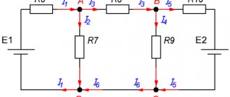
Let us consider, as an example, an electrical circuit in which there are two sources with electromotive forces E1 and E2, internal resistances Ro1, Ro2 and two receivers with resistances R1 and R2. Applying Kirchhoff's second law to “this circuit and choosing the direction of its traversal clockwise,
It will be interesting➡ What is electric power and how to calculate it
we get:
E1 – E2 = IR01 + IR02 + IR1 + IR.
At the same time, e. d.s. E1 and current I coincide with the selected direction of bypassing the circuit and are considered positive, and e. d.s. E2, opposite to this direction, is considered negative. If in an electrical circuit e. d.s. sources of electrical energy when bypassing the corresponding circuit are directed towards each other (see Fig. 24, a), then such a connection is called counter-connection. In this case, based on Kirchhoff’s second law, current I = (E1-E2)/(R1+R2+R01+R02).
Counter direction e. d.s. takes place, for example, on e. p.s. when connecting DC electric motors (they can be considered as some sources of emf) in two parallel groups, as well as when connecting batteries in a battery in parallel.
If e. d.s. sources of electrical energy have the same direction along the contour (Fig. 24, b), then such a connection is called consonant and the current I = (E1-E2)/(R1+R2+R01+R02). In some cases, such inclusion is unacceptable, since the current in the circuit increases sharply.
If there are branches in the electrical circuit (Fig. 24, c), then various currents I1 and I2 pass through its individual sections. According to Kirchhoff's second law, E1-E2=I1R01+I1R1-I2R2-I2R02-I2R3+I1R4.
When composing this equation, e. d.s. E1 and current I1 are considered positive, since they coincide with the accepted direction of bypassing the circuit, e. d.s. E2 and current I2 are negative.
Kirchhoff's first law
Kirchhoff's first law states that in the branches forming a node in an electrical circuit, the algebraic sum of currents is equal to zero (currents entering the node are considered positive, currents leaving the node are considered negative).
Using this law for node A (Figure 1), we can write the following expression:
Figure 1 - Kirchhoff's first law
I1 + I2 − I3 + I4 − I5 − I6 = 0.
Try to apply Kirchhoff's first law yourself to determine the current in a branch. The diagram above shows six branches forming the electrical node B, the currents in the branches enter and exit the node. One of the currents i is unknown.
Write down the expression for node B
I1 + I2 + I3 + I4 + I5 − i = 0 I1 – I2 + I3 − I4 + I5 − i = 0 I1 + I2 + I3 − I4 + I5 − i = 0
Wrong
Result
Great!
Try again(
Selecting the direction of currents
is unknown when calculating the circuit , then when drawing up equations according to Kirchhoff’s law, they must first be selected arbitrarily and indicated on the diagram with arrows. In reality, the direction of currents in the branches may differ from those arbitrarily chosen. Therefore, the selected current directions are called positive directions. If, as a result of the circuit calculation, any currents are expressed as negative numbers, then the actual directions of these currents are opposite to the selected positive directions.
For example
Figure 2
Figure 2a shows the electrical unit. Arbitrarily, we indicate the directions of the currents with arrows (Figure 2, b).
Important! When choosing the direction of currents in branches, two conditions must be met: 1. The current must flow from the node through one or more other branches; 2. At least one current must enter the node.
Let us assume that after calculating the circuit the following current values are obtained:
I1 = -5 A; I2 = -2 A; I3 = 3 A.
Since the current values I1 and I2 turned out to be negative, therefore, the directions of I1 and I2 are indeed opposite to those previously selected (Figure 3).
Figure 3 - the actual direction of the currents is indicated by blue arrows
- I1 − I2 + I3 = 0;
- -5 − (-2) +3 = 0;
- -I1 + I2 + I3 = 0;
- -5 + 2 +3 = 0.
Kirchhoff's second law.
Kirchhoff's second law: in an electrical circuit, the algebraic sum of the emf is equal to the algebraic sum of the voltage drops across all resistances of a given circuit.
where k is the number of EMF sources; m – number of branches in a closed loop; Ii, Ri – current and resistance of the i-th branch.
Application of Kirchhoff's second law
For the ABCDE circuit shown in Figure 4, the arrows indicate the positive directions of the currents (arbitrary). Let's create an equation according to Kirchhoff's second law. To do this, we arbitrarily set the direction of traversing the contour clockwise or counterclockwise. In this example, we choose the direction of traversing the contour clockwise.
Figure 4
When composing equations according to Kirchhoff’s second law, the EMF is written with a “+” sign if its direction coincides with the direction of an arbitrarily chosen circuit bypass. Otherwise, the EMF is recorded with a “-” sign.
Voltage drops are recorded with a “+” sign if the direction of the current in it coincides with the direction of the bypass.
Let's start with emf E1, since its direction coincides with the circuit bypass - we write it with a “+” sign before the equal sign.
Circuit ABCDE E1 =
E2 directed against the contour bypass is written with a “-” sign before the equal sign.
Circuit ABCDE E1 − E2=
Since there is no more EMF in the ABCDE circuit, the left side of the equation is ready.
On the right side of the equation, the circuit voltage drops are indicated, since the directions of the currents I1 and I2 coincide with the circuit bypass - we write the voltage drops with a “+” sign.
Circuit ABCDEE E1 − E2 = I1*R1 + I2*R2
The direction of the I3 current will not coincide with the circuit bypass:
Circuit ABCDE E1 − E2 = I1*R1 + I2*R2 − I3*R3.
The equation for the contour is ready.
Kirchhoff's laws are the basis for calculating an electrical circuit; here are several methods that apply these laws.
The meaning of Kirchhoff's rules
Kirchhoff's laws express the fundamental principles of physics. Their formulations seem very simple and obvious. But in fact, they represent a method that allows you to calculate the electrical parameters of networks of very complex configurations.
Using Kirchhoff's laws, you can create a system of independent equations to calculate the parameters of an electrical circuit. It is important that their number is no less than the number of parameters that need to be determined.
The figure below shows the electrical circuit for which the calculation will be carried out. Using the first law or Kirchhoff's rule, for node A we can write:
I = I1 + I2.
Two currents enter this node and one exits. Next, you need to apply the second rule. To do this, you can select the outer contour. It can be seen that there are two current sources and two resistors. Therefore, the following equations will be obtained:
Here are 2 equivalent formulas. The left side of the equation takes into account the electromotive forces of the two current sources, the right side takes into account the voltage drop across both resistors, taking into account the direction of the currents. Another equation can be obtained from the 2nd law when walking along the right inner contour:
The result is a system that includes three equations with three unknowns:
Using specific data, you can substitute numerical values into the system of equations and find what the current strength is for each branch belonging to node A. When making calculations, it is important to understand that with a fairly complex electrical circuit configuration, it is sometimes difficult to determine the direction of the current strength for each branch.
The first and second laws of Gustav Kirchhoff make it possible to accurately determine not only the magnitude of the current, but also its sign. If in the given example, after calculating the desired values using the presented system of equations, it turns out that the current with index 2 takes a negative value, then this means that in fact it has the direction opposite to that indicated in the figure.
Calculations of electrical circuits using Kirchhoff's laws
Rotation speed: formula
To perform such calculations of electrical circuits, there is a certain algorithm in which the currents for each branch and the voltage at the terminals of all elements included in the EC are calculated. In order to calculate any scheme, adhere to the following order:
- The EC is divided into branches, contours and nodes.
- Arrows indicate the expected directions of movement of I in the branches. Arbitrarily mark the direction in which the contour is walked around when writing equations.
- Write equations using Kirchhoff's first and second rules. In this case, the rules of signs are taken into account, namely:
- “plus” are currents flowing into the node, “minus” are currents flowing out of the node;
- E (EMF) and the reduction in voltage across resistors (R*I) are denoted by a “plus” sign if the current and bypass are the same in direction, or “minus” if not.
- By solving the resulting equations, the required values of currents and voltage drops across the resistive elements are found.
Information. Independent nodes are those that differ from others in at least one new branch. Branches containing EMF are called active, while branches without EMF are called passive.
As an example, we can consider a circuit with two EMFs and calculate the currents.
Example of a diagram for calculations with two E
The direction of currents and circuit bypass is arbitrarily chosen.
Intended directions on the diagram
The following equations are compiled using Kirchhoff’s first and second laws:
- I1 – I3 – I4 = 0 – for node a;
- I2 + I4 – I5 = 0 – for node b;
- R1*I1 + R3*I3 = E1 – acef circuit;
- R4*I4 – R2*I2 – R3*I3 = – E2 – circuit abc;
- R6*I5 + R5*I5 + R2*I2 = E2 – bdc circuit.
Equations are solved using determinant or substitution methods.
Second Law
To calculate complex electrical circuits with several energy sources, Kirchhoff’s second law is used, which can be formulated as follows: in any closed electrical circuit, the algebraic sum of all e. d.s. equal to the algebraic sum of the voltage drops in the resistances connected in series to this circuit, i.e.
E1 + E2 + E3 + . . . = I1r1 + I2r2 + I3r3 + . . .
It will be interesting➡ What is a bridge rectifier and how does it work?
In this case, e. should be considered positive. d.s. and currents, the direction of which coincides with the direction of bypassing the circuit. If two energy sources are included in an electrical circuit, e.g. d.s. which coincides in direction (Fig. 20, a), then e. d.s. the entire chain is equal to the sum of e. d.s. these sources, i.e. E = E1 + E2. If in the circuit e. d.s. sources have opposite directions, then the resulting e. d.s. equal to the difference e. d.s. these sources, i.e.
E = E1 – E2.
Kirchhoff's second law.
When several energy sources with different directions of e.g. are connected in series to an electrical circuit. d.s. general e. d.s. equal to the algebraic sum e. d.s. all sources. When summing up e. d.s. one direction is taken with a plus sign, and e. d.s. opposite direction - with a minus sign. When composing the equations, the direction of traversal of the circuit is chosen and the directions of the currents are arbitrarily specified.
A closed circuit is designated by the letters a, b, c and d. Due to the presence of branches at points a, b, c, d, the currents I1, I2, I3 and I4, differing in strength, can have different directions. For such a chain, in accordance with Kirchhoff’s second law, we can write:
E1 – E2 – E3 = I1(r01 + r1) – I2(r02 + r2) – I3(r03 + r3) + I4r4,
where r01, r02, r03 are the internal resistances of energy sources, r1, r2, r3, r4 are the resistances of energy receivers. In the special case, in the absence of branches and series connection of conductors, the total resistance is equal to the sum of all resistances. If the external circuit of an energy source with internal resistance r consists, for example, of three series-connected conductors with resistances respectively equal to r1, r2, r3, then based on Kirchhoff’s second law, the following equality can be written:
E = I r + I r1 + I r2 + I r3.
With several current sources on the left side of this equality there would be an algebraic sum e. d.s. these sources.
Features of drawing up equations for calculating currents and voltages
First of all, the area to be explored is selected. Then an arrow is arbitrarily placed on each branch indicating the direction of current movement. This is necessary so as not to make mistakes later. When calculating, the directional inaccuracy will be corrected. Each arrow is designated by the letter I with an index. It will be more convenient to consider the section if the arrows are in close proximity to the point of connection of the circuits. Power supplies and resistors are also designated, and resistance is added to the common resistor.
Inside the area, the direction of the bypass is also randomly shown, focusing on possible potentials. It is necessary to compare the direction of current movement. This comparison will show which sign the number should have. If both directions coincide, put a + sign and a – sign if the directions are opposite.
The number of tasks assigned must correspond to the number of unknowns selected. Let's say there are three circuits and it is necessary to calculate their currents, which means that there should also be three formulas. It turns out that the new equation must have at least one new element that is not in the previous problems.
Implications for electrical engineering
Kirchhoff's rules are in addition to other laws. The main difficulty lies in finding areas, since their boundaries are not always easy to detect. After limiting the desired area, it is necessary to select all unknowns. Writing problems is already relatively easy. They are solved like ordinary equations.
Therefore, despite the first difficulties, these rules are still easier to compose and solve than using, say, Ohm's law. Therefore, they are widely used in electrical engineering. To understand how to apply the described method in practice, consider one example.
Meaning in mathematics
There is a circuit consisting of four circuits. The first contains a power source ε1 with internal source resistance r1, the second contains some kind of load R1. The third has a power source and load. The fourth consists of the load. Points B and F are nodes. The arrows next to them show the estimated direction of the current. An arrow inside the area shows the direction of the detour. It is necessary to find the current in the circuits: AK, AB, BF, CD. In theory, we need to create four equations, but since ε1 and R1 are the only ones in the KAB section, we will combine them into one chain. It turns out that you need to create three equations.
The first is taken from the first rule: I1 + I2 + I3 = 0. Since I1, I2 flow into node B, they have a positive sign, and I3 flows out of it, they have a negative sign. We substitute it into the equation and get I1 + I2 – I3 = 0, or in this form I1 + I2 = I3. We take the second and third equations from the second rule. To do this, we use the BCDFB contour and transform the formulation into a mathematical solution: ε2 = I2 × R2 + I3 × R3. For the ACDKA section we obtain, respectively, ε1 = I1 × R1 + I3 × R3. For clarity, we will display them separately.
I1 + I2 = I3
ε1 = I1 × R1 + I3 × R3
ε2 = I2 × R2 + I3 × R3
There were three tasks. Let's decide on the denominations. The first power supply is 6 V, the second is 12 V. Although this cannot be done, because the parallel power supplies must be the same, but this will be useful for us to learn an important lesson. The first resistance is 2 ohms, the second is 4 ohms, the third is 8 ohms.
It remains to insert the data into the equations and we get: for the second number 6 = 2I1 + 8I3, for the third number 12 = 4I2 + 8I3. Next we get rid of the common unknown I3. According to the first point, it is equal to I1 + I2. We substitute this sum instead and get: 6 = 2I1 + 8(I1 + I2), 12 = 4I2 + 8(I1 + I2). Open the brackets and add the same unknowns: 6 = 10I1 + 8I2; 12 = 12I2 + 8I1. To find I1, you need to get rid of I2. To do this, multiply the first equation by 12, and the second by 8 and get: 72 = 120I1 + 96I2; 96 = 96I2 + 64I1. We subtract the second from the first and write down the remainder -24 = 56I1, or I1 = -24/56 = -6/14 A. Why is the current negative?
Because the power sources are different. The voltage at the second source is higher than at the first, so the current flows in the opposite direction. We find I2, for this we insert the value of I1 into any of the last equations: 96 = 96I2 – 64 24/56. Divide the left and right parts by 96 and get: 1 = I2 – (64×24)/(96×56) or move the fractional part to the left, changing the sign. I2 = 1(64×24)/(96×56), after all reductions we get 1 4/14 A. To find I3, we use the first number: I3 = I1 + I2. I3 = -24/56 + 1 4/14 = 1(4×56)/(14×56) – (24×14)/(56×14) = 1,224/784 -336/784 = 1008/784 - 336/784 = 672/774 ≈ 0.87A. We got I1 = -6/14 A, I2 = 1 4/14 A, I3 ≈ 0.87 A.
Kirchhoff's law in chemistry
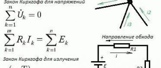
When a system changes its heat capacity during a chemical reaction, the temperature coefficient of the thermal effect resulting from this process also changes. By applying the equation resulting from this law, thermal effects can be calculated in any temperature range. The differential form of this equation is:
∆Cp = d∆Q/dT,
Where:
- ∆Cp – temperature coefficient;
- d∆Q – change in thermal effect;
- dT – temperature change.
Important! The coefficient determines how the thermal effect will change when the temperature changes by 1 K (2730C).
Kirchhoff's theorem for thermodynamics
Maxwell's third equation, as well as the principle of conservation of charges, allowed Gustav Kirchhoff to create two rules that are used in electrical engineering. Having data on the values of resistor resistances and EMF of power sources, it is possible to calculate the flowing I or applied U for any circuit element.
Application of Kirchhoff's laws for alternating current circuits.
Kirchhoff's first law
Formulation: The sum of all currents flowing into a node is equal to the sum of all currents flowing out of the node.
Or The algebraic sum of all currents in a node is zero.
Let me explain Kirchhoff’s first law using the example of Figure 2.
Here the current I1 is the current flowing into the node, and the currents I2 and I3 are the currents flowing out of the node.
I1 = I2 + I3 (1)
To confirm the validity of formulation No. 2, we transfer the currents I2 and I 3 to the left side of expression (1) , thereby obtaining:
I1 - I2 - I3 = 0 (2)
The minus signs in expression (2) mean that currents flow out of the node.
The signs for inflowing and outflowing currents can be taken arbitrarily, however, in general, inflowing currents are always taken with a “+” sign, and outflowing currents with a “-” sign (for example, as happened in the expression (2)).
Kirchhoff's second law.
Formulation: The algebraic sum of the EMF acting in a closed circuit is equal to the algebraic sum of the voltage drops across all resistive elements in this circuit.
Here the term “algebraic sum” means that both the magnitude of the EMF and the magnitude of the voltage drop across the elements can be either with a “+” or a “-” sign.
E1- E2 = -UR1 - UR2 or E1 = E2 - UR1 - UR2
Power balance is a consequence of the law of conservation of energy - the total power produced (generated) by electrical energy sources is equal to the sum of the powers consumed in the circuit.
The power balance condition is that the sum of the powers of all elements of the circuit is zero. In a DC circuit, the power of a section of the circuit is equal to the product of the current and the voltage in that section. If the direction of current and voltage in any area does not coincide, a “–” sign is placed in front of the corresponding term.
№3
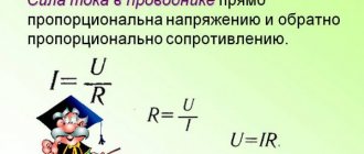
Ohm's law is a physical law that defines the relationship between voltage, current, and conductor resistance in an electrical circuit.
Named after its discoverer, Georg Ohm. Ohm's law states: The current strength in a homogeneous section of a circuit is directly proportional to the voltage applied to the section and inversely proportional to the electrical resistance of this section. And it is written by the formula: I=U/R
Where: I - current (A), U - voltage (V), R - resistance (Ohm). that Ohm's law can be used to calculate hydraulic, pneumatic, magnetic, electrical, light, heat flows, etc.,
Application of Kirchhoff's laws for alternating current circuits.
Ohm's and Kirchhoff's laws are valid for instantaneous currents and voltages.
The sum of complex currents in wires converging at a node in an electrical circuit is zero:
The sum of the complex EMF acting in a closed circuit is equal to the sum of the complex voltage drops in the branches of this circuit:
№4
RECEIVING EMF
The simplest three-phase generator consists of three identical windings, fastened together at angles of 120° and rotating in a uniform magnetic field B with an angular velocity ω (Fig. 1). These are phase windings , or generator phases . They are designated by the letters A, B, C, or by the numbers 1, 2, 3. In this work, the digital designation of phases is used.
In industrial three-phase generators, the phase windings are stationary and are placed at angles of 120° in the stator , as shown in Fig. 2. and the rotating magnetic field is created by an excitation winding placed in the slots of the rotor and powered by a separate DC voltage generator. The rotor is rotated by some kind of engine, for example, a hydraulic or steam turbine.
№7
To reduce the number of wires required to connect the load to the power source, or to reduce the number of ripples in rectifiers, or to increase the transmitted power without increasing the network voltage, different circuits for connecting the windings of both the load and the source are used. The most common connection patterns are delta and star.
When connected by a star, the ends of the phase windings are connected together at one point (in our case shown as x,y,z), which is called the neutral point or zero, and is designated by the letter N. Also, the neutral point (neutral) or zero can be connected to the neutral source, or may not be connected. In the case when the neutrals of the source and receiver of electrical energy are connected, such a system will be called four-wire, and if they are not connected, it will be called three-wire.
But when connected in a triangle, the ends of the windings are not connected to a common point, but are connected to the beginning of the next winding. Namely, the end of the winding of phase A (x is indicated in the diagram) is connected to the beginning of phase B, and the end of phase (y) is connected to the beginning of phase C, and, as you probably already guessed, the end of phase C (z) is connected to the beginning of phase A. It should also be remembered that if, when connected in a star, the system can be either three-wire or four-wire, then when connected in a triangle, the system can only be three-wire.
Rotor rotation principle
The operating principle of the rotor is based on Faraday's electromagnetic law. It rotates due to the influence of electromotive force resulting from the interaction of magnetic fluxes and the rotor winding. In reality it looks like this: between the stator, rotor and their windings there is a certain gap through which a rotating magnetic flux passes. As a result, voltage arises in the rotor conductors, which is the cause of the formation of EMF.
Motors with closed circuit rotor conductors operate slightly differently. These types of motors use squirrel-cage rotors, in which the direction of current and electromotive force is determined by Lenz's rule, according to which the emf opposes the generation of current. The rotation of the rotor occurs due to the magnetic flux moving between it and a stationary conductor.
Thus, to reduce the relative speed, the rotor begins to rotate synchronously with the magnetic flux on the stator winding, tending to rotate in unison. In this case, the frequency of the electromotive force of the rotor is equal to the frequency of the stator supply.
№10
Transformer is a statistical electromagnetic device that converts an alternating current system of one voltage into an alternating current system of another voltage.
Purpose: transformers are used for transmission and distribution of electricity to consumers.
Transformers are: step-up, step-down, single-phase, three-phase and multi-phase. Power, measuring, testing.
The active elements of the transformer are
1. magnetic core 2. windings The magnetic core with the winding is placed in a tank with a transformer with oil, which serves for insulation and cooling
The operation of a transformer is based on the phenomenon of mutual induction . If the primary winding of a transformer is connected to an alternating current source, then alternating current will flow through it, which will create an alternating magnetic flux in the transformer core. This magnetic flux, penetrating the turns of the secondary winding, will induce e. d.s. If the secondary winding is closed to any energy receiver, then under the influence of induced e. d.s. current will begin to flow through this winding and through the energy receiver
№11
PRINCIPLE OF OPERATION OF A SINGLE-PHASE TRANSFORMER. TRANSFORMATION RATIO.
The operation of a transformer is based on the phenomenon of mutual induction, which is a consequence of the law of electromagnetic induction.
Let us consider in more detail the essence of the process of transforming current and voltage. When the primary winding of the transformer is connected to an AC voltage network, a current will begin to flow through the winding, which will create an alternating magnetic flux in the magnetic circuit. A magnetic flux, penetrating the turns of the secondary winding, induces in it, which can be used to power the load.
. The ratio of the number of turns of the transformer windings is called the transformation ratio k.
Thus, the transformation ratio shows how the effective values of the EMF of the secondary and primary windings relate.
At any moment of time, the ratio of the instantaneous values of the EMF of the secondary and primary windings is equal to the transformation ratio.
The voltage ratio on the windings of an unloaded transformer is indicated in its passport.
OPERATING PRINCIPLE in detail: Under the influence of the supplied alternating voltage U
1, an alternating current
I
1 arises in the primary winding of the transformer, which, passing through the turns of the transformer winding, excites an alternating magnetic flux
F
1
.
This flux induces
e
1 and
e
2 in the transformer windings.
EMF e
1 balances the main part of
the U
1 source, EMF
e
2 creates voltage
U
2 at the output terminals of the transformer.
I2
appears , which forms its own magnetic flux
Ф2
, superimposed on the flux of the primary winding.
As a result, a total magnetic flux Ф
=
Ф
msin2p
ft
(
Ф
m is the amplitude value of the magnetic flux of the transformer;
f
is the frequency of alternating current)
,
coupled with the turns of both windings of the transformer.
The flow Ф
is called the main flow or the flow of mutual induction.
When this flux changes, the main EMFs - e
1 and
e
2 - are induced in the transformer windings.
The transformation ratio of a transformer is a value that expresses the scaling (conversion) characteristic of a transformer relative to some parameter of the electrical circuit (voltage, current, resistance, etc.).
For power transformers, GOST 16110-82 defines the transformation ratio as “the ratio of the voltages at the terminals of two windings in no-load mode”, and “is taken equal to the ratio of the numbers of their turns”
№12
THREE-PHASE TRANSFORMERS
Three-phase power transformers are mainly used in power transmission lines.
The magnetic core of a three-phase transformer has three rods, each of which contains two windings of the same phase.
To connect the transformer to power lines, there are bushings on the tank lid, which are porcelain insulators with copper rods running inside them. High voltage inputs are designated by the letters A, B, C, low voltage inputs are designated by the letters a, b, c. The neutral wire input is located to the left of input a and is designated O.
A feature of a three-phase transformer is the dependence of the transformation ratio of linear voltages on the method of connecting the windings.
There are mainly three methods used to connect the windings of a three-phase transformer:
1) connection of the primary and secondary windings with a star (Fig. 7.8, a);
2) connection of the primary windings with a star, the secondary windings with a triangle (Fig. 7.8, b);
3) connection of the primary windings with a triangle, secondary windings with a star (Fig. 7.8, c).
Let us denote the ratio of the number of turns of the windings of one phase by the letter k, which corresponds to the transformation ratio of a single-phase transformer and can be expressed through the ratio of phase voltages:
k = w2/w1≈U2ph/U1ph
with the same number of turns of the transformer windings, its transformation coefficient can be increased or decreased by √3 times by choosing the appropriate winding connection diagram.
Special transformers are devices that allow you to change the characteristics of the electric current: balance the phases, reduce ripple, change the number of phases, stabilize the current, change the frequency of the current (frequency multipliers) or perform amplification (magnetic amplifiers).
When starting electric motors as well as various laboratory installations, autotransformers . Autotransformers are also widely used as household electrical devices, designed to increase voltage from 110 to 220 V or decrease it from 220 to 110 V.
To reduce the voltage from 220 or 380 V to 60-70 V, a welding transformer (electric arc welding) or up to 14 V (resistance welding) is designed. Welding transformers are designed to operate at high currents - about 300 A, and in short circuit mode
To switch on measuring instruments, as well as relays, instrument transformers . Typically, instrument transformers are considered step-down transformers. As a result, they allow the use of conventional instruments for measuring high voltages, currents, and powers, thereby increasing the safety of the operating personnel.
Power transformer is a transformer designed to convert electrical energy in electrical networks and in installations intended for receiving and using electrical energy.
Current transformer is a transformer powered by a current source. Typical application is to reduce the primary current to a value used in measurement, protection, control and signaling circuits
A pulse transformer is a transformer designed to convert pulse signals with a pulse duration of up to tens of microseconds with minimal distortion of the pulse shape
№13
Kirchhoff's first law
Formulation: The sum of all currents flowing into a node is equal to the sum of all currents flowing out of the node.
Or The algebraic sum of all currents in a node is zero.
Let me explain Kirchhoff’s first law using the example of Figure 2.
Here the current I1 is the current flowing into the node, and the currents I2 and I3 are the currents flowing out of the node.
I1 = I2 + I3 (1)
To confirm the validity of formulation No. 2, we transfer the currents I2 and I 3 to the left side of expression (1) , thereby obtaining:
I1 - I2 - I3 = 0 (2)
The minus signs in expression (2) mean that currents flow out of the node.
The signs for inflowing and outflowing currents can be taken arbitrarily, however, in general, inflowing currents are always taken with a “+” sign, and outflowing currents with a “-” sign (for example, as happened in the expression (2)).
Kirchhoff's second law.
Formulation: The algebraic sum of the EMF acting in a closed circuit is equal to the algebraic sum of the voltage drops across all resistive elements in this circuit.
Here the term “algebraic sum” means that both the magnitude of the EMF and the magnitude of the voltage drop across the elements can be either with a “+” or a “-” sign.
E1- E2 = -UR1 - UR2 or E1 = E2 - UR1 - UR2
Power balance is a consequence of the law of conservation of energy - the total power produced (generated) by electrical energy sources is equal to the sum of the powers consumed in the circuit.
The power balance condition is that the sum of the powers of all elements of the circuit is zero. In a DC circuit, the power of a section of the circuit is equal to the product of the current and the voltage in that section. If the direction of current and voltage in any area does not coincide, a “–” sign is placed in front of the corresponding term.
№3
Ohm's law is a physical law that defines the relationship between voltage, current, and conductor resistance in an electrical circuit.
Named after its discoverer, Georg Ohm. Ohm's law states: The current strength in a homogeneous section of a circuit is directly proportional to the voltage applied to the section and inversely proportional to the electrical resistance of this section. And it is written by the formula: I=U/R
Where: I - current (A), U - voltage (V), R - resistance (Ohm). that Ohm's law can be used to calculate hydraulic, pneumatic, magnetic, electrical, light, heat flows, etc.,
Application of Kirchhoff's laws for alternating current circuits.
Ohm's and Kirchhoff's laws are valid for instantaneous currents and voltages.
The sum of complex currents in wires converging at a node in an electrical circuit is zero:
The sum of the complex EMF acting in a closed circuit is equal to the sum of the complex voltage drops in the branches of this circuit:
№4
What is Kirchhoff's stress rule (Kirchhoff's second law)?
The principle known as Kirchhoff's stress rule (discovered in 1847 by the German physicist Gustav R. Kirchhoff) can be stated as follows:
“The algebraic sum of all voltages in a closed loop is zero”
By algebraic I mean, in addition to taking into account quantities, taking into account signs (polarities). By contour I mean any path traced from one point in a chain to other points in that chain, and finally back to the starting point.
Laws for magnetic field
Kirchhoff's rules have also found their application in the calculation of magnetic circuits. Kirchhoff's first law for a magnetic circuit looks like this:
Simply put, the sum of all magnetic fluxes passing through a node is zero.
The second law, as applied to magnetic fields, is as follows: “The sum of the magnetomotive forces in a circuit is equal to the sum of the magnetic stresses.” The formula looks like this:
Kirchhoff derived rules that have an absolute applied nature. With their help you can solve practical problems in electrical engineering. The widespread use of these rules is explained by the simplicity of the formulation of the equations and the possibility of solving them using standard methods of linear algebra.
Demonstration of Kirchhoff's voltage law in a series circuit
Let's look at our sequential circuit example again, this time numbering the points in the circuit to represent voltages:
Figure 1 – Demonstration of Kirchhoff’s voltage law in a series circuit
If we were to connect a voltmeter between points 2 and 1, the red test lead to point 2, and the black test lead to point 1, the voltmeter would register a reading of +45 volts. For positive readings on digital meter displays, the "+" sign is usually not shown, but rather is implied. However, for this tutorial, the polarity of the voltage readings is very important, so I will explicitly show the positive numbers:
E2-1 = +45 V
When voltage is indicated with a double subscript (the characters "2-1" in the notation "E2-1"), it means the voltage at the first point (2) measured relative to the second point (1). The voltage reported as "Ecd" will mean the voltage value shown by a digital multimeter with a red test lead at point "c" and a black test lead at point "d": the voltage at point "c" relative to point "d".
Figure 2 – Ecd value
If we were to take the same voltmeter and measure the voltage drop across each resistor, going around the circuit clockwise with the red test lead of our multimeter at the point in front and the black test lead at the point behind, we would get the following readings:
E3-2 = -10 V
E4-3 = -20 V
E1-4 = -15 V
Figure 3 – Determination of voltages in a series circuit
We should already be familiar with the principle common to series circuits that the individual voltage drops add up to the total applied voltage, but measuring the voltage drop in this way and paying attention to the polarity (mathematical sign) of the reading reveals another aspect of this principle: all measured voltages in the sum is equal to zero:
[begin{matrix} E_{2-1} = & +45 V &text{voltage at point 2 relative to point 1} \ E_{3-2} = & -10 V & text{voltage at point 3 relative to point 2} \ E_{4-3} = & -20 V & text{voltage at point 4 relative to point 3} \ E_{1-4} = & -15 V & text{voltage at point 1 relative to point 4} \ hline \ & 0 In end{matrix}]
In the example above, the outline is formed by the following points in the following order: 1-2-3-4-1. It doesn't matter where we start or what direction we go when following a contour; the sum of the stresses will still be zero. To demonstrate this, we can use the same circuit to calculate the voltages in the 3-2-1-4-3 circuit:
[begin{matrix} E_{2-3} = & +10 V &text{voltage at point 2 relative to point 3} \ E_{1-2} = & -45 V & text{voltage at point 1 relative to point 2} \ E_{4-1} = & +15 V & text{voltage at point 4 relative to point 1} \ E_{3-4} = & +20 V & text{voltage at point 3 relative to point 4} \ hline \ & 0 In end{matrix}]
This example can be clearer if we redraw our sequential diagram so that all components are represented on one straight line:
Figure 4 - Changing the representation of a daisy chain
This is still the same sequential circuit, only with slightly redistributed components. Note the polarity of the voltage drops across the resistors in relation to the battery voltage: the battery voltage is negative on the left and positive on the right, while all the voltage drops across the resistors are oriented in the other direction (positive on the left and negative on the right). This is because resistors resist the flow of electrical charge being pushed by the battery. In other words, the "pushing" applied by the resistors against the flow of electrical charge must be in the opposite direction to the source of the electromotive force.
Here we see what the digital voltmeter will show on each component in this circuit if the black wire is on the left and the red wire is on the right:
Figure 5 – Measuring voltages in a series circuit
If we were to take that same voltmeter and measure the voltage between combinations of components, starting with the single R1 on the left and working our way through the chain of components, we would see how the voltages add up algebraically (to zero):
Figure 6 – Measuring the sum of voltages in a series circuit
The fact that series voltages add up shouldn't be a secret, but we noticed that the polarity of these voltages makes a big difference in how these values add up. When measuring the voltage across R1 – R2 and R1 – R2 – R3 (I use the double dash symbol “–” to denote the series connection between resistors R1, R2 and R3), we see larger voltages being measured (albeit negative) , because the polarities of the individual voltage drops have the same orientation (plus on the left, minus on the right).
The sum of the voltage drops across R1, R2 and R3 is 45 volts, which is the same as the battery output voltage, except that the polarity of the battery voltage (negative left, positive right) is opposite the voltage drops across the resistors, so when measuring the voltage across the entire chain of components we get 0 volt.
The fact that we should get exactly 0 volts along the entire line should also not be a secret. Looking at the diagram, we see that the leftmost part of the line (left side of R1, point number 2) is directly connected to the rightmost part of the line (right side of the battery, point number 2), which is necessary to complete the circuit.
Since these two points are directly connected, they are electrically common to each other. Thus, the voltage between these two electrically common points must be zero.
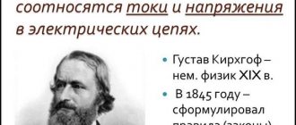
Story
Kirchhoff joined the ranks of German scientists in the nineteenth century, when the country, which was on the threshold of the industrial revolution, required the latest technology. Scientists were searching for solutions that could accelerate industrial development.
They were actively involved in research in the field of electricity, because they understood that it would be widely used in the future. The problem at that time was not how to make electrical circuits from possible elements, but how to carry out mathematical calculations. This is where the laws formulated by the physicist appeared. They were very helpful.
The algebraic sum of currents arriving at a node and leaving it is equal to zero. This simultaneously follows from another law - the constancy of energy.
2 wires go to the node, and one goes out. The value of the current flowing from the node is the same as the sum of it flowing through the other two conductors, i.e. going to him. Kirchhoff's rule explains that, in a different situation, a charge would accumulate, but this does not happen. Everyone knows that any complex chain can be easily divided into separate sections.
But it is not easy to determine the path along which it passes. Moreover, in different areas the resistance is not the same, therefore the distribution of energy will not be uniform.
In accordance with Kirchhoff's Second Rule, the energy of electrons in each of the closed sections of the electrical circuit is equal to zero - the total value of voltages in such a circuit is always equal to zero. If this rule were violated, the energy of electrons passing through certain areas would decrease or increase. But this is not observed.
Demonstration of Kirchhoff's voltage law in a parallel circuit
Kirchhoff's voltage rule (Kirchhoff's second law) will work for any circuit configuration at all, not just simple series circuits. Notice how this works for the following parallel circuit:
Figure 7 – Parallel circuit of resistors
In a parallel circuit, the voltage across each resistor is equal to the supply voltage: 6 volts. Summing up the voltages along the 2-3-4-5-6-7-2 circuit, we get:
[begin{matrix} E_{3-2} = & 0 V &text{voltage at point 3 relative to point 2} \ E_{4-3} = & 0 V & text{voltage at point 4 relative to point 3} \ E_{ 5-4} = & -6 V & text{voltage at point 5 relative to point 4} \ E_{6-5} = & 0 V & text{voltage at point 6 relative to point 5} \ E_{7-6} = & 0 V & text{voltage at point 7 relative to point 6} \ E_{2-7} = & +6 V & text{voltage at point 2 relative to point 7} \ hline \ E_{2-2} = & 0 V end{matrix}]
Please note that I designated the final (total) voltage as E2-2. Since we started our step-by-step path along the contour at point 2 and ended at point 2, the algebraic sum of these voltages will be the same as the voltage measured between the same point (E2-2), which of course must be zero.
The validity of Kirchhoff's law on voltages regardless of the circuit topology
The fact that this circuit is parallel and not series has nothing to do with the validity of Kirchhoff's voltage law. In this respect, the circuit could be a "black box" (the configuration of its components is completely hidden from our view) with a set of exposed terminals between which we can measure the voltage - and Kirchhoff's voltage rule will still hold true:
Figure 8 – Validity of Kirchhoff’s law for voltages, regardless of the circuit topology
Try traversing the diagram above in any order, starting at any pin, and returning to the original pin, and you will find that the algebraic sum of the voltages is always zero.
Moreover, the "circuit" we trace for Kirchhoff's second law does not even have to be the actual path of current flow in the truest sense of the word. All we have to do to comply with Kirchhoff's voltage rule is to start and end at the same point in the circuit, counting the voltage and polarity drops as we move between points. Consider the following absurd example, following a 2-3-6-3-2 “loop” in the same parallel resistor circuit:
Figure 9 – Parallel circuit of resistors