Electric drive classification
General information about the electric drive
History of electric drive development
The first electric drive was carried out in 1838 by the St. Petersburg academician B. S. Jacobi, who, based on the DC motor with a rotating shaft that he developed in 1834, used it powered by a galvanic battery to drive the paddle wheels of a pleasure boat. At the same time, the lack of economically viable sources of electrical energy did not allow the use of electric drives in production at that level of development.
Essentially, the electric drive began to be introduced into production and replaced thermal and other drives of machines and mechanisms with it after it was developed by the Russian electrical engineer M. O. Dolivo-Dobrovolsky in 1889-1891. systems for the production, distribution and consumption of three-phase alternating current, including his development of a three-phase asynchronous motor. The obvious economic advantages of centralized production of three-phase alternating current electricity and the ease of its distribution have led to the fact that the electric drive, gradually displacing other types of drive of machines and mechanisms, has taken a dominant place in many sectors of the national economy.
Historically, the electric drive, due to its exceptional importance and widespread use, as a result of which electric drives account for the consumption of over 60% of the electricity generated in the country, was singled out from general technological electrical installations for separate consideration.
Electric drive
Electric drive
called an electromechanical system, consisting in a generalized form of electric motor, converter, transmission and control devices and designed to drive the executive bodies of the working machine and control this movement (Fig. 1.1).
The main purpose of an electric drive as a technological electrical installation is the conversion of electrical energy into mechanical energy of movement of the executive bodies of machines and mechanisms. In some cases, when implementing regenerative braking modes, reverse energy conversion is also possible.
Electric motor device
provides direct conversion of electrical energy into mechanical energy.
Converter device
carries out the transformation of the electrical energy of the source into the form necessary for the electric motor device. In the simplest case, the functions of a converting device in an electric drive are performed by various types of switching equipment: contactors, magnetic starters, thyristor switches, etc. In a more complex case, controlled semiconductor converters: rectifiers, voltage regulators, frequency converters, etc.
Rice. 1.1. Functional diagram of an automated electric drive:
M – electric motor device; PRB – converting device; TRD – transfer device; CU – control device.
Transfer device
converts the mechanical energy of the electric motor device into the form necessary for the consumer of mechanical energy. Couplings, belt and chain drives, and gearboxes are used as transmission devices in electric drives. In terms of functionality, the transfer device is similar to the converter, with the only difference being that the converter converts electrical energy, and the transfer device converts mechanical energy.
Mechanical energy consumers
– these are the executive bodies of working machines and mechanisms of various technological installations.
Converter, electric motor and transmission devices form the energy part
electric drive.
Information part
The electric drive is represented by a control device, which in some cases is classified as information-control device. It receives reference and feedback signals at the input, and at the output produces control signals for the energy part of the electric drive. The high-level control device includes microprocessor means, micro- and mini-computers.
An important energy indicator of an electric drive is the efficiency factor (efficiency), the value of which, neglecting the relatively low power consumption of the control device, is determined by the expression
(1.1)
where , , , are, respectively, the efficiency of the electric drive, converter, electric motor and transmission devices.
Since the efficiency values of the converting and transmission devices are quite close to unity and depend little on the degree of load, then in general the efficiency of the electric drive is determined by the value of the efficiency of the electric motor device. As is known, it is also quite high and for rotary motion electric motors it is 60-95% at rated load. Lower efficiency values correspond to low-speed, low-power electric motors. At powers above 1 kW, the nominal value of the efficiency of electric motors, and, accordingly, the electric drive, as a rule, exceeds 70%.
The advantages of an electric drive are low noise level during operation and absence of environmental pollution, a wide range of powers and angular speeds, availability of control of angular speed and, accordingly, the productivity of technological installations, relative ease of automation, installation and operation compared to heat engines, for example internal combustion.
Electric drive classification
Electric drives are classified according to their main characteristics as follows.
According to the method of transferring mechanical energy
The executive body of a technological installation is distinguished: group, single, individual and interconnected electric drive. In a group electric drive, an electric motor drives several executive bodies of one or more working machines. In a single one there is one executive body. In the individual case, the individual parts of the electric motor represent a part of the executive body, for example, an engine and an executive body in the form of a motor wheel. In an interconnected electric drive, several motors drive one executive element, for example, the drive of the traction element of an extended conveyor by several electric motors.
According to the presence of a mechanical transmission device
There are geared electric drives and gearless drives. In a gearbox, an electric motor transmits rotational motion to a transmission device containing a gearbox. In a gearless type, the transmission of motion from the electric motor is carried out either directly to the working element, or through a transmission device that does not contain a gearbox.
By type of current and type of electric motor device
distinguish between AC and DC electric drives; asynchronous, synchronous, valve, etc.
Based on the principle of angular velocity and position control
The executive body is divided into electric drives: unregulated, adjustable, servo, software-controlled, adaptive. Unregulated - designed to drive the executive body of a working machine at one operating speed; the drive parameters change only as a result of disturbing influences. Adjustable - to communicate a constant or variable speed to the machine's executive body, the drive parameters can be changed under the influence of the control device. Follower - automatically working out the movement of the executive body of the working machine with a certain accuracy in accordance with an arbitrarily changing command signal. Program-controlled – controlled in accordance with a given program. Adaptive – automatically selecting the structure or parameters of the control system when operating conditions of the machine change in order to develop an optimal mode.
By type of converter used
electric drives of the following systems are distinguished: UV-D (controlled rectifier - motor), SHIP-D (pulse-width converter - motor), MU-D (magnetic amplifier - motor), TRN-AD (thyristor voltage regulator - asynchronous motor), IF -AD (frequency converter - asynchronous motor), etc.
By degree (level) of automation
The electric drive can be: manual, automated and automatic. Non-automated electric drives - with manual control, are not used in production processes according to production safety requirements. Automated electric drives – controlled by automatic control of parameters; The most common are asynchronous electric drives with a power of up to 200 kW with synchronous speeds from 750 to 3000 rpm, which are low cost, easy to install and operate, and have increased reliability compared to other types of electric drives. Automatic electric drives - in which the control action is generated by an automatic device without operator participation, provide flexible control of technological processes and their full automation based on hardware or software.
Literature
1. Shichkov L.P. Electric drive. - M.: KolosS, 2006. - 279 p.: ill. – (Textbooks and teaching aids for students of higher educational institutions).
2. Chilikin M.G., Sandler A.S. General electric drive course: Textbook for universities. – 6th ed., add. and processed – M.: Energoizdat, 1981. – 576 p., ill.
Content
1. General information about the electric drive. 1
1.1. Historical reference. 1
1.2. Electric drive. 1
1.3. Classification of electric drive. 4
Literature. 6
Short-term operating mode is characterized by the fact that during the operating period the heating of the electric motor does not reach a stable state, and the break in operation is so long that when it resumes, the engine temperature is close to the ambient temperature. In this mode, for example, the boom lift motors of a single-bucket excavator operate. Their work lasts for several minutes, after which they turn off for a long time. The short-term mode graph is shown in Fig.
In the intermittent mode, working periods alternate with pauses, i.e., with periods of stopping the electric motor. During the period of operation, the engine does not have time to completely heat up, and during the period of stoppage, it does not have time to completely cool down. The intermittent mode is further divided into periodic and non-periodic mode (Fig. 3, s and d). In such modes, electric motors of cranes, elevators and other lifting mechanisms operate. The mode under consideration is characterized by the PV indicator (on duration), which is equal to the ratio of the duration of the working period to the duration of the cycle (working period and stop).
Rice. 3. Simplified operating schedules of electric drives under various modes: a - long-term; b - short-term; a - periodic, repeated-short-term; g - non-periodic intermittent (t - engine heating temperature)
Based on the nature of the load change over time, the following modes are distinguished: 1) operation at a constant load that does not change over time. This is how, for example, fan motors and centrifugal pumps work; 2) work under variable load, changing after certain, equal periods of time. This mode is typical for electric motors of piston pumps; 3) work under an irregularly variable load, changing haphazardly at different intervals. In this mode, the engines of tower cranes and other lifting mechanisms operate.
According to the nature of the change in rotation speed depending on the load, they distinguish: 1) operation at a constant or almost constant rotation speed, when a constant rotation speed is provided by synchronous motors, and an almost constant speed, independent of load changes, is provided by parallel-excited DC electric motors and three-phase asynchronous motors with low resistance in the armature (rotor) circuit; 2) operation with a slightly falling rotation speed, when a slight decrease in engine speed from idle to maximum load is acceptable. This mode is provided by three-phase asynchronous motors, parallel-excited DC motors and some commutator-type AC motors; 3) work with a strongly decreasing rotation speed, which is provided by electric motors with high resistance in the rotor circuit, series-excited DC electric motors, three-phase and single-phase commutator-type AC motors.
Based on the nature of the rotation speed control, the following modes are distinguished: 1) operation at an unregulated speed, which can be provided by any electric motor without devices for speed control. Most construction machines operate at a constant speed; 2) variable speed operation provided by AC and DC motors equipped with special speed control devices. rotation. Compared to AC motors, DC motors offer greater flexibility in terms of speed control and range. This mode (with speed control) is required for a number of construction machines, such as construction cranes, excavators, etc.
Electric drive - AC or DC?
The annual sales growth rate for variable speed drives is approximately 6%, while the growth rate for AC drives is 8%, and the market size for DC drives remains more or less stable. This article is intended for end users, OEMs, system integrators, and other drive engineers to outline the benefits of choosing one of the two main types of variable speed drive, DC or AC, for a variety of applications.
Which drive solution should you choose - DC or AC?
Power static converters
Microprocessor-based drives used in both AC and DC drives have now reached a very high technical level, which (within acceptable technological limits) allows the use of an
AC drive
where
a DC drive
. However, the traditional DC drive (1-quadrant and 4-quadrant) continues to play an important role, especially in applications where it is necessary to provide highly dynamic modes with constant torque, stringent overload requirements over a wide speed range and energy recovery back to net.
Main selection criteria
The first thing a user must do is to objectively evaluate the options available on the variable speed drive market that technically meet the application/process requirements. The main criteria for this assessment should be: 1. The total cost of purchasing the variable speed drive and the required additional equipment 2. Ongoing operating costs:
- service;
- production costs, efficiency, etc.;
- required placement area.
3. Technological and innovative aspects:
- dynamic response, acceleration time; 4-quadrant operations; emergency stop, etc.
- weight and dimensions characteristics.
4. Operational reliability, suitability of drives:
- compliance with international requirements and standards IEC, GOST R, EN, CE-EMC; CSA, UL, etc.;
- environmental conditions; degree of housing protection; on-site repairs
5. Impact on the external environment:
- mains voltage distortion
- EMC
6. Space requirement for inverter and motor 7. Heat dissipation
Comparison of the main characteristics of DC and AC drives in industrial applications
A comparison is made between 6-pulse 3-phase independently excited DC thyristor drives [hereinafter referred to as SDC
] and 3-phase AC electric drives based on a frequency converter with pulse-width modulation and an asynchronous motor [hereinafter referred to as
VFD
- variable frequency drive], in the following typical categories: PPT - P = 11 kW ... 5200 kW; U = 200 V … 1190 V VFD – P = 0.75 kW … 2000 kW; U = 380 V … 690 V
DC drive
Variable Frequency Drive
To a first approximation, there are not many significant differences between these drives; however, upon closer examination, the characteristic features of the drives and the difference in the physical principles of operation are revealed. Further in the article, aspects of the differences between drives are revealed on the following points:
- characteristics of motors as electromechanical converters
- characteristics of electrical energy converters
- 4-quadrant drives
- impact on the external environment
- modernization of DC drives
Differences between DC and AC motors
Most users have the following general understanding of electric motors: “DC motors
complex, requiring frequent maintenance, which makes their operation expensive; In addition, they have a low degree of protection. AC motors (asynchronous motors) are simple and reliable, do not require maintenance, have a lower price, and also have a higher degree of protection.” This classification may be true for many simple applications; Nevertheless, it is advisable to subject this general verdict to more careful consideration!
Mechanical characteristics of DC drives
The commonly used independent ventilation (in approximately 85% of variable speed drives up to 250 kW) guarantees good heat dissipation from the DC motor rotor over the entire speed range.
Typical applications requiring constant torque over a wide speed range: wire drawing mills, reciprocating compressors, hoists, ropeways, extruders, ...
Mechanical characteristics of variable frequency drives
The commonly used self-ventilation (approx. 90% of variable speed drives up to 250 kW) in standard asynchronous motors is not effective over the entire speed range. At low speeds, heat removal is virtually impossible.
Typical applications with reduced torque at low speed, corresponding to the characteristic in Fig. 4: pumps, fans, etc. with a quadratic dependence of load on speed...
Characteristics of the power-speed ratio in S1 mode of DC and AC motors:
(1) Unlike a standard induction motor with a fixed base (nominal) speed (synchronous speeds of 3000/1500/1000/… rpm at 50 Hz), a DC motor can be designed with a base speed ranging from approximately 300 up to 4000 rpm for each operating point. (2) Depending on the size, DC motors (both compensated and uncompensated) can have a field weakening range of 1:3 or 1:5. (3) The power limitation is related to the maximum torque of the asynchronous motor, which decreases inversely to the square of the speed (1/n2). (4) Power limitation is due to the reduction in switching capacity of the brushed DC motor
.
Comparison of motor performance shows that a DC motor is superior to an induction motor for continuous operation at low speeds and for a wide range of speeds at constant power. The short-term overload capacity depends not only on the motor parameters, but to a large extent on the characteristics of the frequency converter / thyristor converter. The wider the speed range over which a motor can produce maximum power, the better it can be adapted to processes that require constant torque throughout the entire speed range. Typical application: winding devices.
• Sizes, moments of inertia and acceleration times:
The main technical differences between
DC and AC
, methods of generating magnetic flux and dissipation of power losses also cause different dimensions (height of the shaft rotation axis H) and rotor moment of inertia (Jrotor), with the same rated motor torque.
DC
motors have a significantly lower axis height
H
and rotor mass than asynchronous motors, and therefore have a lower rotor moment of inertia Jrotor, which is a significant advantage in highly dynamic applications such as test benches, flying shears, and reversible drives, since this affects the acceleration time and dynamic response of the motor in 4-quadrant applications (motoring and braking).
• Wide speed range at constant power (field weakening operation or excitation control range):
Specialized drive applications such as winder/unwinder drive, test bench, winch, etc. require a very wide speed range at constant power.
In this case, the traditional field weakening operating mode of a separately excited
is particularly cost-effective. This means: a wide speed range at which the engine can produce maximum power (the length of the horizontal characteristic line in Fig. 5 from nG to n1), a smaller engine power reserve Pmax(motor) / Pmax(load) is required.
• Engine maintenance:
Currently, depending on the complexity of the application,
DC motor
is approximately 7000...12000 hours, thanks to a modern commutator assembly, carbon brushes and an optimized excitation field. Depending on the mechanical operating conditions, the lubricant replacement interval in DC/AC motors can be comparable, and often less, than the life of the brushes of a commutator motor.
• Engine protection degree:
Historically, since the 20s,
DC motors
have been developed mainly for variable speed drives, which led to the use of internal forced independent ventilation (in approximately 85% of motors up to 250 kW). Standard asynchronous motors began to be used actively in the 70s/80s and were mostly (approx. 90% up to 250 kW) manufactured with surface self-ventilation, since variable frequency drives were not widespread at that time. In fact, all asynchronous motors with a power of approx. up to 1400 kW have a degree of protection IP 54 as standard, thanks to their simple and robust design. For operation in hazardous areas, explosion-proof asynchronous motors are almost exclusively used. The asynchronous motor has won a leading position for itself and has proven its effectiveness in those industrial sectors that are characterized by aggressive environmental conditions, high levels of pollution and dust.
• Weight and location for engine installation:
The lower weight and dimensions
of DC motors
(standard protection
IP 23
) compared to asynchronous motors (standard protection IP 54) are especially important for applications where the motor must be moved along with the load (e.g. large cranes, overhead cranes) , or in systems where compact placement is important (drilling rigs, ski lifts, marine applications, printing machines, etc.).
Differences between Thyristor DC Converters and Frequency Converters
• Switching and conversion of electrical energy:
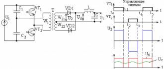
Block diagram of a 1-quadrant DC drive
The transition of current from one thyristor to another begins with a starting pulse, and after that continues in a linearly interconnected mode. This means that the voltage between the switched phases of the network is polarized in such a way that the current of the newly opened thyristor increases, and turns off the previous thyristor, reducing its current to zero. The thyristors are switched naturally (by mains voltage) when the current passes through zero, and the thyristors are switched off without any problems even with significant overload. Therefore, thyristors can be selected not by peak current, but by the average rated load current.
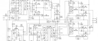
Block diagram of the frequency converter
Although the input bridge rectifier of a frequency converter works like a DC drive, the current rectified by it must be converted back to 3-phase AC using an inverter. Since direct current does not have any zero crossings, switching elements ( IGBT transistors)
) must interrupt the full load current. When the IGBT turns off, current flows through the freewheeling diode to the opposite pole of the DC voltage. Switching occurs without voltage control, but is possible at any time, regardless of the shape of the mains voltage.
Result:
Switching in frequency converters occurs at high frequencies and a high-frequency component appears in the output voltage, and problems with electromagnetic compatibility may arise. In DC-DC converters there is only one power conversion circuit (AC → DC). Frequency converters have two energy conversion circuits (AC → DC and DC → AC), i.e. Power losses are doubled compared to DC drives. The power losses obtained empirically are as follows: PPT - 0.8% ... 1.5% of the rated power; VFD - 2% ... 3.5% of rated power. Space required to place a converter cabinet with a power of 100 kW or more: PPT - 100%, VFD - 130% ... 300%. This advantage of DC drives results in a reduction in the size and cost of the control cabinet and cooling system.
• Output currents of AC and DC converters; engine noise; winding insulation load, electromagnetic compatibility (EMC):
PPT
• Motor Current/Noise: The voltage supplied to the motor consists of segments from the sinusoidal mains voltage. The motor current is DC with a superimposed AC component from the bridge rectifier, so noise emissions are not an issue in a DC drive.
• Motor torque ripple: The pulsating torque (foscill = 6 x fline = 300 Hz or 360 Hz), resulting from current ripple, is superimposed on the fundamental torque and is significantly higher in frequency than the mechanical resonant frequencies. For this reason, there will be no problem for applications such as winders/unwinders, etc.
• Motor voltage/winding insulation: The maximum voltage that is applied to the DC motor terminals is equivalent to the peak line voltage (UN • √2 ).
• EMC: For the reasons mentioned above, the installation costs required to reduce electromagnetic emissions (to meet EMC requirements) are relatively small in DC drives.
VFD
• Motor Current/Noise: Noise emission in variable frequency drives is highly dependent on the selected clock frequency in each application.
• Relative harmonic components in the motor torque: The pulsating torque resulting from the harmonic components of current and voltage (deviation from ideal sine) in amplitude and frequency is very dependent on the operating point and operating principle of the frequency converter. The likelihood of induced vibrations in the drive system (engine, clutch, transmission, mechanical components, etc.) is correspondingly greater.
• Motor voltage/winding insulation: The output signal of the IGBT PWM inverter contains steep voltage edges, which in the case of a long motor cable (> 10 m) can lead to 2-fold peak overvoltages at the motor. As a result, the impact on the insulation of the motor windings increases, which can lead to its aging and breakdown. This situation can be corrected by using a motor with a higher insulation class, or by installing a choke at the output of the frequency converter.
• EMC: Electromagnetic emissions in variable frequency drives, especially those associated with long cable runs, may require additional measures and equipment.
• Impact on mains voltage:
Linear currents of DC drives with
a 6-pulse thyristor bridge
will always contain, in addition to the main harmonic, the 5th, 7th, 11th and 13th harmonics in the corresponding percentages: 22%, 14%, 9%, 7.6% .
In case of operation of several DC drives connected to the same mains voltage source, they will slightly balance each other due to different phase sequences, and the overall mains voltage distortion will be reduced. In frequency converters, switching IGBT transistors
practically does not create
low-frequency
harmonic distortions, but
high-frequency
components are significant.
• Reactive power:
Both types of drives
(PPT and NPP)
consume reactive power from the network. Its size is not significant in variable-frequency drives, but in DC drives it is more significant and depends on the engine speed. Frequency drives have preference in this matter.
Empirical values for DC drives: 1-quadrant applications - cos ≈ 0...0.9 4-quadrant applications - cos ≈ 0...0.85
Empirical values for variable frequency drives: 1-Q applications (with diode input bridge) - cos ≈ 0.99 4-Q applications (with thyristor input bridge and regeneration to the network) - cos ≈ 0.9
Modernization of existing DC drives.
When the question arises about whether it is worth upgrading an existing DC drive or whether it is cheaper to completely replace it with an AC drive, you need to approach this issue carefully and consider all the arguments, both pros and cons.
There are basically several upgrade levels available:
- Complete replacement of the DC drive (converter and motor) with a new modern DC drive.
- Replace only the converter if the engine is in good condition.
- Replacing one of the converter modules with a new one.
- Replacing analogue control electronics with digital ones without changing the power section (recommended only for powers above 1 MW).
- Complete replacement of the entire drive system with a variable frequency drive.
When answering the question of which approach to choose in each specific case, it is important to evaluate a number of criteria:
- Could there be a need to change the drive in the future (change in the type or nature of the load, operating conditions, etc.)?
- What is the condition of the individual system components (reliability, age, operating costs)?
- Before deciding to replace the DC drive with a VFD
, consider the following points:
- Costs for laying new cables.
- Place for placing the frequency converter.
- Will switching equipment need to be replaced?
- Possibility and complexity of mechanical installation of a new engine
- Duration of all drive replacement work./
Price comparison of DC and AC drive systems
(drive + motor or complete control + motor cabinet) Based on today's prices for DC and AC drives, taking into account the above advantages and disadvantages of various solutions, the following assessment can be used as a guide: 1-Q drives < 40...80 kW → VFDs are less expensive 4-quadrant drives < 40…60 kW (Frequency converter + braking (module) resistor); → PDC less expensive Regenerative 4-Q drives > 15 kW → PDC less expensive
Conclusion
The main disadvantage of analog DC drive
is low noise immunity, difficulty in setting up and instability of parameters. A tachogenerator is used as a speed feedback sensor, which has the same disadvantages as a commutator motor. For reversible drives, a diode bridge must be installed after the tachogenerator, which limits the control range at low speeds due to loss of feedback. In the case of synchronizing mechanisms with various drives in the “master-slave” mode, a frequency converter is much preferable, because Digital sensors such as encoder, resolver or sin/cos converters are used as speed sensors, which makes it possible to build systems with electric shafts. The presence of additional devices (options) of frequency converters allows you to expand the functions of the latter: increase the number of inputs/outputs, use modern buses and communication protocols, use the drive in positioning devices, monitor the temperature conditions of the motor and drive, use the drive in virtual cam mode (variable rotation speed per one revolution of the shaft) and much more.
Modern microcontrollers that control frequency converters make it possible to process data over a period of several tens of microseconds (ten years ago this time was 200 mS), which made it possible to expand the feedback control range to 1:1000 with an accuracy of maintaining a speed of 0.2 revolutions throughout range, which brings frequency drives closer to servos.
However, given the steady growth of the variable speed drive market, the DC drive market size is expected to remain more or less stable for some period. This view is confirmed by the latest market research.
The comparison of the two types of drive systems made in this review shows that whether the right choice of DC or AC drive is entirely dependent on the specific application.
- Should 4-quadrant operation with recuperation be ensured?
- Expected to operate at low speed for extended periods of time?
- Do you want less heat from the converter?
- Frequent dynamic acceleration and braking are expected?
- Need a wide speed range at constant power (>1:1.5)?
- Are you satisfied with the motor protection degree < IP54
? Working in an unpolluted environment? - Is it possible to provide periodic engine maintenance?
- Do you require compact dimensions and low weight of the inverter and motor?
The more questions you answered “Yes” to
, the more relevant it is for you to use a DC drive!
| Application of Optidrive E2 frequency converters in Modbus networks | Electric drive - AC or DC? | Selection and application of variable-frequency electric drives with a power of up to 500 kW at production facilities in the gas industry. |