The most common reason for the breakdown of a “warm floor” system is the failure of thermostats (thermostats) and its sensors. Let us recall that the thermostat is a control device with a housing, operation indication and electronics. And the sensor is a thermistor with an extension wire, which is located in the heating zone.
How to repair a heated floor thermostat and, if necessary, replace the heated floor sensor? We wrote about this
Repair of a heated floor sensor in an apartment
The most common reason for the breakdown of a “warm floor” system is the failure of thermostats (thermostats) and its sensors.
Let us recall that the thermostat is a control device with a housing, operation indication and electronics. And the sensor is a thermistor with an extension wire, which is located in the heating zone. How to repair a heated floor thermostat and, if necessary, replace the heated floor sensor? We wrote about this
Method of checking the floor system
Before checking a heated floor with a tester for the presence of faults, certain preparation is required, which consists of making sure that the house has power supply and there is a supply to the thermostat. Usually it is enough to look at the indicator light located on this device.
If there is electrical current, you need to check the temperature setting. Sometimes it happens that the regulator is at the minimum value - for this reason it seems that the system is not functioning. To avoid such a misunderstanding, you should carefully inspect the device.
If you can verify that electricity is supplied, the temperature level is set correctly, but the floor remains cold, you need to move on to more serious diagnostic methods.
If you have knowledge about electricity and how to diagnose a heated floor with a multimeter, you can do the test yourself, which also requires a screwdriver. A multimeter can be replaced with a voltage indicator, but it is not entirely informative if accurate diagnostics are needed.
In some cases, purchased equipment may need to be verified. But it must be taken into account that an electrical cable that is not covered with a tie is not turned on in the air. Before filling it can be checked, but power supply is only allowed for 5 minutes and no more, and the wire should be unwound.
Tags: machine, sconce, type, harm, choice, generator, house, , sign, cable, like, capacitor, circuit, , installation, power, multimeter, voltage, setting, nominal, connection, polarity, rule, principle, check , wire, , work, calculation, regulator, resistor, relay, repair, switch, row, garden, system, connection, resistance, term, stabilizer, ten, current, transistor, transformer, , phase, shield, electricity, power supply, effect
Repair of floor heating thermostat
To find a breakdown, you must first remove the thermostat.
Important! Before you begin repairing the heated floor thermostat, be sure to turn off the power to it if this device is connected to a separate circuit breaker, or turn off the electricity in the entire apartment, i.e. by unscrewing the plugs or turning off the input switch.
Damage to the thermostat and how to fix it
I. The control lamp on the front panel of the thermostat does not light up, it does not turn on at all, or not only its display.
In these cases it is necessary:
Liked this:
This entry was posted on 02.12.2015, 17:42 and is filed under Anatomy, About everything, Objects. You can follow any responses to this entry through RSS 2.0. You can scroll to the end and leave a comment. Replies are currently not allowed.
#1 by Igor Olenin on 01/13/2016 — 15:01
Wonderful article! Respect to the author. Saved 7 thousand rubles for the repair of two thermostats at an official service center. Spare parts (ionistor and capacitor X2) cost 300 rubles. The ionistor really has nothing to do with it. Changed it - the problem did not go away. Then I replaced the capacitors and everything worked! In addition to the article, the exact characteristics of spare parts for replacement from Chip and Dip: EECS0HD334H, 0.33 F, 5.5 V, 10 mm, 1207H, Ionistor, B32922-C3334-K, 0.33 uF, 305V, 10%, X2, EMI suppression capacitor.
Device type and installation location
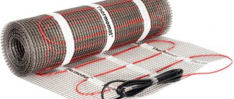
The reliability of the underfloor heating system itself is exceptional and can last for decades. If heating does not occur, most often this means that the reason is the thermostat or the sensor. The latter device is a thermistor protected by a glass bulb and a gel shell with a securely insulated copper conductor 3 meters long connecting it to the thermostat.
This is what the sensor looks like for tile and porcelain stoneware floors. Under carpet and laminate, another type in a plastic case is installed. The sensor usually comes with a protective corrugated tube with a diameter of 16 mm. It is located under the heating element at a distance of 0.5-1 m from the wall exactly in the middle between the turns of the heating cable and is fixed in place with foil tape.
Incorrect cable selection, poor thermal insulation
The inability of a heated floor to reach a comfortable temperature may be due to the use of an insufficiently powerful heating cable.
Normally, the heating time to the temperature set on the thermostat is about 30 minutes, after which the system should turn off the heater (the light on the thermostat will go out).
If the cable takes much longer to heat up or does not turn off at all, it means it does not have enough power.
Incorrect power selection is often due to the following: the owner calculates the power of the heating system, including underfloor heating, using a very common, but not very correct method - multiplying the area of the home by 0.1 kW. The resulting figures are so inaccurate that they can easily be equated to “pulled out of thin air.”
In each specific case, specific heat loss during the coldest period of the year can vary greatly, since this value depends on a number of factors:
The calculation methodology can be found in specialized literature or in SNiP dedicated to heating, ventilation and air conditioning.
A warm floor will not work well even if too thin a layer of heat insulation has been laid under the heating element. A significant portion of the heat produced will be used for other purposes - it will go into the ground or into the room below.
Signs of a malfunctioning temperature sensor and steps to replace it
In addition to the system stopping, a malfunction of the temperature sensor is indicated by the flickering of a red light on the panel or its color changing to green when turned on. A fault warning may appear on the display. And you will have to replace the heated floor temperature sensor with a new one with your own hands.
It's not difficult at all if you follow this procedure:
- Removing a faulty sensor begins with turning off the power supply.
- The device is then disconnected from the wires connected to the terminals on the rear panel. Their location may be separate from the terminals of the block, but they are easy to find by the designation next to the inscription “sensor”.
- The resistance of the disconnected sensor is checked. It must be indicated in the device passport and is usually in the range of 5-15 kOhm. If the real resistance corresponds to the passport value, the fault is hidden in poor contact.
- To be completely sure, you should reconnect the wires to the terminals. If the sensor works, but its resistance differs from that specified in the passport, and the difference is more than 20%, the device requires replacement.
- It must be removed from the corrugated tube and a new device must be placed there with wires connected to it to the same length as the failed one was located.
Useful tips for replacing a heated floor temperature sensor with your own tutorials
For safety reasons, replacing the heated floor sensor yourself is done when the system is de-energized. Temperature sensors from different manufacturers may have differences in nominal resistance. In order for the temperature sensor to exactly match the thermostat, you need to purchase a replacement device from the same company.
The corrugated tube that should go into the junction box is often of a diameter that makes it difficult to install a new sensor. Simply put, it is difficult to push it there. To facilitate this task, home craftsmen use various tricks, such as lubricating the sensor wire with liquid soap or vegetable oil to facilitate its movement in a tight tube.
To facilitate the procedure for replacing a temperature sensor in a heated floor, many people subsequently replace the corrugated pipe with a piece of metal-plastic pipe of the appropriate diameter. Such a pipe has smooth walls on the inside, which greatly facilitates the placement of a new temperature sensor in it.
How to solve low voltage problem
If you notice that an electric heated floor does not heat well at low voltage or voltage surges, you can get out of the situation by installing a stabilizer for your home network. This device will ensure normal operation of the heating system, both at low and high voltage.
That's all I wanted to tell you about how to repair an electric heated floor with your own hands. As you can see, all the faults are quite simple and no special electrical knowledge is required to solve the problem. At the same time, if you are too lazy to repair the system yourself, the technician will charge you at least 5,000 rubles (the average cost of installing a coupling on a damaged section of a heating cable).
Repair of electric underfloor heating. Price.
offers repair of heated floors at the prices indicated below. We search for the location of a break or damage without opening the floor using special instruments. We will install a special repair coupling on the cable at the point of damage. Soldering and electrical tape are not applicable in principle in the case of a heating cable. We will replace the thermostat and temperature sensor.
Reasons for failure of heated floors:
- Mechanical damage, such as cuts, squeezing (deformation) of the heating cable. The heating cable may not be completely cut, but only cut or cut to the heating core - this is quite enough for the system to stop working. How long will she live with such damage? This is individual and depends on many factors; as a rule, the critical period of operation of heated floors is the first three years.
- Heating cable operation in air. This happens when air voids remain under the tiles. After all, as we all know from school physics lessons, air and tile adhesive heat up at different rates, and it is in the places of air voids that the heating core of the heated floor burns out.
- Damage to the thermostat or temperature sensor,
We provide a guarantee for all underfloor heating repair work . Repair parts are always in stock.
Ask your question to our consultants by phone in St. Petersburg: (812) 493-57-98, 8-911-250-55-43. (Call from 9:00 to 21:00)
Photos of damage to the heated floor:
Typical malfunctions of electronic thermostats
Poor contact of wires in the terminal block
One of the main reasons for thermostat failure is poor contact when connecting wires to it, which is demonstrated in the repair example. Sometimes the screws in the terminal block are tight and it appears that the wire is clamped tightly enough, which in fact is not the case.
Therefore, before installing the thermostat, it is imperative to tighten each of the terminal screws all the way and unscrew them back in order to assess how hard the screws need to be tightened when clamping the wires.
To prevent wire insulation from getting into the terminal holes, it must be removed to a sufficient length.
Temperature sensor failure
Thermostats provide for checking the serviceability of the thermistor and informing in case of its failure. In simple thermostats, the indicator LED begins to blink, and in display thermostats, an error message is displayed on the screen.
When reporting a sensor error, first of all you need to make sure that its connection to the thermostat is secure. If it is connected securely, then disconnect the sensor from the circuit and use a multimeter to measure its resistance, which is indicated in the passport or on the device body.
If there is no data, then it should be assumed that, depending on the ambient temperature, the resistance of the thermistor is from 6 to 30 kOhm. Additionally, you can verify that the temperature sensor is working properly by placing your hand around it. When heated by the body, the resistance should change, usually decreasing.
If the resistance of the temperature sensor does not fall within the range specified above and does not change when it heats up, then the thermistor is faulty and must be replaced.
Failure of radio-electronic components
If the thermostat does not show signs of operation, then the reason may be the failure of the current-limiting resistor and capacitor, the electrolytic capacitor (usually it is inflated from above) to smooth out pulsations and the electromagnetic relay.
If you have a little experience in checking and replacing radio components on a printed circuit board, then a home technician can easily handle such faults. If you don’t have a multimeter, you can repair it by simply replacing the radio components listed above with known good ones.
Thermostat repair
It's no secret that sometimes thermostats fail, and at the most inopportune moment. There are several reasons for this sad event. The most common is incorrect installation: an error in the connection diagram (such as mixing up wires and terminals, too much load), painting the installed thermostat, installing the thermostat in a damp room. With such errors, the thermostat either immediately fails or its service life is significantly reduced. Trust the installation of the thermostat only to a professional electrician.
The second reason is related to the design features of thermostats. The fact is that basically their power supplies are built according to a transformerless circuit with a ballast capacitor (almost all regulators from such companies as: OJ Electronics, Eberle, Raychem, some DEVI), or according to a key stabilizer circuit such as, for example, Devireg D530, Devireg D535 , Veria B45, Veria T45.
Read Self-leveling floor thickness maximum
Such thermostats are sensitive to impulse noise in the power supply network, which occurs when devices such as a welding transformer, hammer drill or electric lawn mower are turned on near the controller, which often happens in country houses. In such conditions, it is better to use regulators with transformer power supplies that do not allow impulse noise to pass through (for example, the Busch Jaeger NTC100 regulator).
Connection diagram for an infrared heater via a mechanical thermostat
This, in my opinion, is the most optimal connection diagram for an infrared heater.
You can use any - mechanical, electromechanical or digital (electronic). When implemented, many of the most important disadvantages of previous methods are eliminated.
In this case, you will need to carry out the electrical wiring from the electrical panel to the installation site of the infrared heater in advance. An option with external installation is possible, for example, in a cable duct - but this method is less safe and often spoils the appearance of the room.
Electrical wiring is laid from the electrical panel or other source to the thermostat, and from there it goes to the heater.
The most difficult thing here is connecting the wires inside the regulator. As an example of the most affordable and widespread mechanical thermostat, I took the BALLU BMT-1 model. His example, the diagram below, shows how to correctly connect the conductors inside.
Most mechanical thermostats have similar installation patterns, you can see this in the example of the ZILON model, which we reviewed earlier. In addition, instead of mechanical ones, digital (electronic) sensors are often used; they have a greater number of operating modes, adjustment options and external appearance. An installation example of one of them is available HERE.
Main disadvantages
— Larger financial costs than previous schemes
For implementation, it is necessary to first carry out the electrical wiring, purchase additional electrical equipment, a thermostat and cable.
— The need for additional electrical work
The need for preliminary work on laying cables and installing regulators requires the involvement of appropriate electrical specialists. Or the knowledge and skills, and most importantly the time, to do this work with your own hands.
— Impossibility of installing several IR heaters or one powerful one
The thermostat contacts rarely allow the possibility of connecting to it a current greater than 10A, in rare cases 16A. Accordingly, the maximum total power of heaters should not exceed 2-3 kW.
Advantages of connecting an IR heater via a thermostat
— Possibility of automatic adjustment of room temperature
You get a fully automated heating system. Which itself maintains the temperature, turns on and off at the programmed time.
— Ease of management
You choose the installation location of the thermostat yourself and its location is not tied to the installation location of the heating elements.
— Completely safe hidden electrical wiring
Electrical wiring is done in advance. In this case, you can choose the correct cross-section of conductors, the type of their connection in junction boxes, etc. In this case, all conductors are hidden, significantly reducing the likelihood of cable damage.
- Appearance
Cables hidden behind the wall decoration and the ability to choose the appearance of control devices allow you to preserve the original appearance of the interior and even decorate it.
CONCLUSION: If we ignore the installation difficulties and additional costs for equipment and electrical wiring, this is an almost ideal option in terms of functionality for small rooms. Where one or two heaters are often enough, the total current consumption of which does not exceed 10-16A to maintain a comfortable temperature, there is no better way to think about it.
If you have the task of heating a large room using several electrical heating devices or energy-intensive, powerful models, the best option for you is to connect through a thermostat and contactor.
To receive a discount on DEVI heated floors, call!!
Did your heated floor suddenly stop heating or did not turn on immediately after laying the tiles?
Heated floor thermostat
There can be only two reasons for malfunctions of a heated floor: thermostat . for some reason does not supply voltage to the heating cable and/or the heating cable circuit is open. In this article we will look at the first one - the thermostat is not working .
Thermostat.
what a thermostat is and how it works here. A thermostat malfunction is easy to diagnose . Usually this can be done by any technically literate person who knows how to use a multimeter.
To diagnose the thermostat, it must be removed .
Removing the floor heating thermostat
IMPORTANT! Before starting work, be sure to turn off the power to the thermostat . if it is powered through a separate circuit breaker, or de-energize the entire apartment by turning off the input switch or unscrewing the plugs.
Thermostat malfunction
- Possible malfunctions of the thermostat and how to deal with them:
The thermostat does not turn on. The indicator lamp on the front panel does not light up or the display does not turn on.
In this case, you first need to check whether there is power at the supply terminals. To do this, with the power off, remove the thermostat from the installation box without disconnecting the wires. Then, turning on the power, you need to check the presence of voltage at the supply terminals of the thermostat. The supply terminals are marked with the letters N (zero) and L (line/phase). The voltage is checked either using a multimeter (tester) - between the supply terminals or using a test screwdriver - at terminal L and, just in case, at terminal N. According to the rules, a blue wire (wire with a blue stripe) must be connected to terminal N. and to terminal L - a white or red (brown) wire. If there is no voltage on the supply wires, the problem is not in the underfloor heating system, but in the wiring or switchboard. If your diagnostics have revealed that the phase wire fits into terminal N of the thermostat, the so-called “rephasing”, you need to swap the supply wires, first turning off the voltage. “Rephasing” can lead to failure of the thermostat.
Read Decorating a toilet with PVC panels with your own hands
If the power is present and correctly phased, but the control lamp or display on the thermostat does not turn on, it means the thermostat has failed. Such a malfunction cannot be corrected under “field” conditions; it is easier to replace the entire thermostat. If the warranty period for the thermostat has not yet expired, you should have it replaced under warranty.
The thermostat turns on, but does not enter operating mode. On the front panel only the green light is on or the display turns on, but the floor heating icon is not displayed.
In this case, the initial check consists of setting a higher temperature by turning the thermostat wheel upward or by setting on the display a temperature that is obviously higher than the current room temperature (30-350). If, in this case, the thermostat does not return to operating mode, the thermostat will probably need to be replaced.
When the thermostat is turned on, the red light on the panel immediately changes color to green or blinks red, and the display indicates a malfunction of the temperature sensor.
The temperature sensor has failed. It is quite possible to replace it yourself, provided that the temperature sensor is initially correctly installed in the corrugated tube leading into the junction box. To do this, you need to first turn off the power, remove the thermostat, disconnect the temperature sensor wires (as a rule, these are the thinnest wires) connected to the corresponding terminals on the rear panel. The terminals are designated by the word “sensor” or “sensor” and can be located separately from the main terminal block. After disconnecting the sensor, you can check its resistance. The resistance of temperature sensors from different manufacturers is different and ranges from 5-15 KOhm (KiloOhm). The electrical resistance of your sensor is indicated in the thermostat data sheet. Please note that some household testers cannot measure electrical resistance greater than 2 kOhm.
If the resistance of the temperature sensor corresponds to the rated value, poor contact in the terminals is possible. To check, you can once again carefully connect the sensor wires to the appropriate terminals. The thermostat should work . If this does not happen, the thermostat must be checked at a service center. If the resistance of the sensor differs from the nameplate by more than 20%, the temperature sensor must be replaced. Since the sensor is already disconnected from the thermostat, all you have to do is pull it out of the corrugated tube and replace it with a new one. The new sensor must be placed in the corrugated tube to the same length as the old one went there. I draw your attention to the fact that the temperature sensor is an accessory of the thermostat, and not the heated floor, and the nominal resistance of sensors from different manufacturers varies and sensors from one manufacturer may not fit the thermostat of another. Therefore, when purchasing a temperature sensor separately, be sure to specify the name of your thermostat and the manufacturer.
Read Length of floor plinth
If for some reason you were unable to replace the failed temperature sensor yourself, our technician will do it quickly and accurately or suggest other ways to solve the problem.
The thermostat enters operating mode. The red light on the front panel is on or the heating icon is displayed on the display, but the floor does not heat up.
In this case, most likely, the heating core of the underfloor heating cable has broken. The article Why does underfloor heating not work will help you understand the reasons?
You can diagnose a break in the following way. From the previously de-energized thermostat, disconnect the wires leading to the heated floor system and measure the electrical resistance between them. The resistance must correspond to the value specified in the passport for your heated floor. If the resistance tends to infinity and/or is measured in MegaOhms, unfortunately, your heated floor actually has a broken heating core . Our technician will repair the break using special tools and equipment.
If you do not have the time or opportunity to study the causes of the malfunction, just call 958-81-66 - heated floor repair specialist, Yuri Igorevich (St. Petersburg)
System Damage
Next, you need to check the temperature sensor and the electric floor heating system itself. To do this, use a multimeter to measure the resistance of the temperature sensor and the cable (or film) itself. If the value does not correspond to the passport value, then the devices are faulty. “0” on the tester display will indicate a short circuit, and “1” or infinity will indicate an open circuit (can occur as a result of mechanical damage). We talked about how to repair a heated floor with your own hands in the corresponding article!
You can find out the nominal resistance of the heating element using the formula: R=U2/P, where U is 220 Volts, and P is the power of the electric floor (you can look it up in the passport or use an approximate calculation of 150 W/m2).
We also draw your attention to the fact that the resistance of the temperature sensor decreases when heated, so if the difference compared to the passport data is small, this indicates its serviceability. If the resistance differs significantly from that declared by the manufacturer, then the sensor is faulty
https://youtube.com/watch?v=f9lTMSrwI-4
Do-it-yourself floor heating thermostat repair
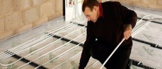
To carry out quick and high-quality diagnostics, which will allow you to find a break in the heated floor or other damage to the heating cable, special devices are required that are not available at home. This manual was developed by the leading European manufacturer of electric underfloor heating - the Warmup company and is recommended primarily for craftsmen involved in the maintenance and repair of heated floors. “Warm floor” systems, made on the basis of a heating cable, are actively used for heating various types of premises. They are mounted under tiles, laminate, linoleum, carpet, etc., are easy to use and provide comfortable conditions for human life. However, like any equipment, they break down from time to time. Let's consider the method of localizing damage in "Warm Floor" systems using Greenlee devices, which are used by the Warmup company.
Functionality of thermoregulation sensors
When choosing a sensor, everyone should base their choice on the required characteristics, such as:
- Which type of sensor suits you? Larger, programmable, mechanical or electrical;
- How do you want to install the sensor, in or outside of the system;
- Number of channels one or two;
- The sensors can be of different styles and colors to suit you;
- Methods of thermoregulation, sensory, remote or electrical.
Where to start repairing a heated floor
The technology and procedure for performing repair work depend on the design of the heated floor and the automation used. For domestic purposes, three types of heating elements are used:
- Cable heater, in the form of a single or three-core wire laid in a concrete screed for a heated floor;
- A film graphite element rolled out under laminate or parquet and connected to an automatic regulator;
- A water floor, which is a network of plastic tubes laid at the base of tiles or any other floor covering.
For your information! There is an opinion that most often cable heating floors fail. This is not entirely true. A cable or wire heating element is considered the most insidious, and the reliability of a heated floor directly depends on the quality of the material used and the professionalism of the electrician who performed the installation work. First of all, you will need to check the serviceability of the supply wiring, with which the heated floor heater is connected to the household network. The wiring of a conductor heating system, even a Chinese one, uses copper wires, which are highly reliable, while in the walls of an apartment, especially old ones, aluminum wiring is almost always laid, which easily burns out at the connection points.
For water heaters, the presence of pressure at the inlet to the underfloor heating system and the capacity of the tubes are checked, only then they begin to look for a wet spot on the floor covering. It is possible that the reason is not in the heating structure, and expensive repairs of heated floors under the tiles simply will not be required.
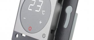
Thermostat E 51.716
The Spanish-made ORBIS Clima ML thermostat is a compact device.
Heating film TM
Infrared heating film TM is a film electric heater for creating heating systems.
Our services
Installation of an electric heating system "warm floor"
Services for installation and connection of heated floors are relevant within the Sverdlovsk and Chelyabinsk regions.
Installation of an electric heating system "heating ceiling"
Services for installation and connection of a heating ceiling are relevant within the Sverdlovsk and.
/> Administrator July 20, 2019
Overview of the programmable thermostat E 51.716 . A device for heating ceilings, heated floors and other heating devices using electricity.
Purpose and operating principle of E 51.716
The programmable thermostat E 51.716 performs a control and control function in a heating ceiling or underfloor heating system. Using a built-in and/or remote temperature sensor, it constantly monitors the state of the room temperature and issues commands to turn heating devices on or off. Designed for internal use and designed to operate at ambient temperatures of -5/+50 °C.
The programmable E 51.716 provides three operating modes: automatic (the temperature is maintained within a given corridor), manual (commands are given by the user) and programmable (individual mode).
E 51.716 has a convenient LCD display, six modes of temperature change during the day, and the ability to programmably adjust the operation of heating devices for a week .
Main characteristics of E 51.716
The thermostat E 51.716 has small dimensions (86 x 90 x 46 mm) and is built into a standard mounting box. The liquid crystal display displays the main operating parameters.
- Thermostat type is electronic.
- Installation type: built-in.
- Programmable mode - yes.
- Voltage, Unom – 220 V, 50 Hz.
- Load power, max – 3520 W.
- Load current, max – 16 A.
- Thermostat power consumption is 2 W.
- The temperature control range is 5–55 °C.
- Regulation error – ±0.5 °С.
- Built-in temperature sensor – yes.
- Remote temperature sensor – yes (NTC, 10 kOhm), cable length 3 m.
- Degree of protection – IP 20.
- White color.
- Overall dimensions – 86 x 90 x 43 mm.
- Gross weight – 330 g.
- Warranty – 1 year.
- Country of origin: China.
Features of the thermostat E 51.716
The device has an attractive design and is equipped with an informative LCD screen with blue backlighting. Convenient buttons located on the front panel make it easy to make the necessary settings. The locking function, which is provided in E 51.716, protects the device from accidental pressing and child abuse.
During a temporary power outage, the developers of the device have provided a power supply (battery) in it. After the power supply is restored, the device returns to the specified settings.
Below is a description of the symbols that indicate the main control elements of the E 51.716.
Connection diagram for thermostat E 51.716 for heating ceiling
When connecting the E 51.716 thermostat to a “heating ceiling” heating system based on infrared film electric heaters, the following diagram is used.
The phase wire coming from the electrical panel is fixed to contact No. 1 of the device . The “zero” wire is connected to pin No. 2 . The phase wire going to the heaters is connected to contact No. 4 . The neutral wire from the electrical panel is connected directly to the film electric heaters .
Note! Before connecting, be sure to take into account the calculated load of infrared heating. If it exceeds 10 A , then direct connection of the thermostat is not recommended. Despite the fact that the manufacturer indicates a permissible maximum load of 16 A , in order to avoid possible problems and increase the safety of the system, our experts recommend including a modular contactor in the circuit.
Connection diagram for thermostat E 51.716 for heated floors
Below is an example of a connection diagram that uses a remote sensor that controls the floor temperature. Connection diagram for heated floors.
Installation procedure for thermostat E 51.716
Thermostat E 51.716 is a built-in device. For its installation (when a standard box is used), standard mounting boxes (brands K-201, UHL4, 068TT) are perfect. The holes for fastening are located horizontally. If surface mounting of the device is required, a special box for it will have to be purchased additionally.
1. Using a flathead screwdriver, carefully separate the outer frame from the thermostat housing.
2. Remove the metal plate on which the device will be fixed.
3. Install the plate into the mounting box, which has been previously prepared for the device and fixed in the wall at the recommended level (1.0-1.2 m from the floor), and secure it with screws.
4. Connect and secure the wires according to the connection diagram above. Next, install the thermostat housing onto the mounting plate, and then snap the outer frame into place.
Contents of delivery
Thermostat E 51.716 is supplied assembled, completely ready for connection and use. The device kit includes:
Causes of heated floor failure
- The thermostat does not receive 220 V;
- The heated floor sensor has failed;
- The thermostat does not work;
- Breakage of the heated floor (heating element).
How to determine what exactly happened to your heated floor? To do this, you can call a heated floor specialist or a qualified electrician, but unfortunately, an electrician cannot always determine the cause. In order for an ordinary electrician and even you to identify the cause of a heated floor malfunction, I am giving you a short video and Instructions for diagnosing a heated floor.
Lack of power
The first step is to make sure that there is power to the heating system. As a rule, the film or heating cable is connected through a thermostat to which voltage is applied. If the indicators on the temperature controller display are lit, then there is power; if the indicators are missing or not lit, you will have to check manually why the heated floor is not heating. You need to take a multimeter and check if there is voltage at the input contacts. We described in detail how to use a multimeter in the corresponding article.
By the way, low voltage in the network is also the reason why the heated floor does not heat up to the required temperature. If 200 volts are supplied to the terminals rather than 220, heating efficiency is reduced by 20%. To solve this problem, you need to install a voltage stabilizer in your house.
The video shows another way to check the regulator:
If there is voltage at the input, you need to make sure that it is normally supplied to the heating cable itself or infrared film. To do this, make sure that no one accidentally touched the settings, because... Perhaps the temperature is simply set to a minimum, as a result of which the heating does not turn on. Also check that the wires are securely connected to the terminals. Poor contact is also the reason why an electric heated floor does not heat or heats up poorly.
Is everything okay with the connection and settings? Measure the voltage at the output of the thermostat (the terminals to which the heating system itself is connected). When enabled, it must comply with the network parameters. If this is not the case, the thermostat will have to be replaced.
You can verify that the thermostat is malfunctioning by connecting the heated floor directly to the network. If the floor covering starts to heat up, then the problem is with the regulator.
We repair cable heated floors
The insidiousness of the conductor system lies in the fact that the destruction of the heating wire, as a rule, occurs slowly. Most often, a break occurs due to damage to the insulation and the central core during the assembly of the heated floor. After pouring the concrete screed, electrochemical corrosion completely corrodes the metal within a couple of months, and the contact is broken.
What to check first
The most difficult stage of repair is to find a fault or location of damage in the entire heating system of the room. Diagnosing and identifying the reasons why a heated floor does not work or heats very weakly or unevenly costs a tidy sum, so specialized offices are willing to undertake a preliminary inspection of the heating system.
The sequence of repair of a warm electric floor consists of the following stages:
- We check the operation of the thermostat. If the device is faulty, the temperature of the heated floor will “float” or not be regulated at all. In this case, you will need to replace the thermostat with a new “box” of the same model;
- If the problem cannot be resolved by replacing the thermostat, the heated floor sensor will need to be repaired;
- If the automation check does not produce results, inspection and repair of the heated floor cable using special equipment will be required.
The diagnostic procedure alone for a complete diagnosis of heated floor wiring can cost 3-6 thousand rubles, so it always makes sense to try to repair an electric heated floor yourself before calling a technician. This is not as difficult as it might seem at first glance, but there is one limitation. You should not undertake repairs to an electrical cable floor if you do not even have basic skills in working with electrical wiring.
A standard RTC70 thermostat will cost 1.5-2 thousand rubles, a temperature sensor with a Danfoss WTF type switching wire costs up to 500 rubles. It is best to buy a temperature sensor, and during the repair, at the first opportunity, replace it in the heated floor system.
Repair of floor heating thermostat
The situation with the repair of the heated floor thermostat is ambiguous. If the system has a touch or remotely controlled version of the sensor, then most likely you will not be able to repair the device yourself.
Cheaper models with a mechanical rotary temperature controller, everything is simple here. The adjustment knob is mounted on the collar of a variable resistor, which wears out quite quickly during operation and begins to spark inside the housing. To repair, you just need to select a resistor of the same value and resolder the regulator on the board.
The thyristor of the load control key is repaired in a similar way. You don’t even have to check it with a tester, but immediately solder it to a new, known-good element of the same model and characteristics.
Finding the break point of the heated floor core
Initially, it is necessary to restore the cable laying line in the concrete screed. To do this, you can use any of the hidden wiring detection devices. Based on the indication, you can easily restore the cable laying route and even apply markings to the concrete base.
You can also determine the location of the break using a thermal imager, if you have one on your farm. Even the simplest models of Chinese heat scanners make it possible to see the heating distribution when the network is turned on. The thermal imager will not show the specific point of the cable break, but it will help determine the place where concrete needs to be knocked down for repair.
Next, the electrical power to the heated floor is turned off, and with a small chisel, hammer and brush, the concrete is carefully knocked down along the marking line. The damaged area must be determined visually. Pouring water onto the core and trying to determine the break point with a multimeter, as some “experts” advise, is strictly prohibited.
The location of the wiring break is most accurately determined using a locator, consisting of two blocks. The master module, which generates electrical oscillations of high frequency and voltage, is connected to the cable connector. The second block is a hand-held remote control with a digital indicator of the electric field strength level. By moving the remote control over the laying line, you can accurately determine the point of damage in the cable wiring of the heated floor.
The system can be successfully used even if the heated floor is covered with floor tiles.
Sealing a heated floor cable
After the break point has been found, the place where the heated floor is repaired is thoroughly cleaned and blown away from dust, and the wiring check process is performed in the following order:
- At the ends of each wire, 10-15 mm from the edge, remove the shielding foil or braiding, polymer insulation, the conductors are protected and tinned for subsequent repairs;
- Both ends of the damaged cable core are connected with pieces of copper, insulated wire to an ammeter;
- Turn on the power to the heated floor for a short period and check the current value using the device. If the current consumed by the heated floor is within 1-5 A, then the cable can be repaired; there are no other points of damage.
To repair the heating core, a heat-shrinkable tube is placed on one end of the wire, then the contacts are soldered with a stranded wire or connected with a repair copper sleeve and then compressed. Place a heat shrink tube over the joint, heat it up, and thereby isolate the contact.
All that remains is to repair the heated floor screed and lay the floor covering.
Causes of malfunctions
When using a heated floor, problems may arise related to its operation. There are two types of malfunctions - complete loss of heating and the inability to control it. For some breakdowns, you will have to remove the finishing coating and dismantle the screed, and for others, you will have to repair the temperature controller.
The reason for the breakdown of the heated floor may be a malfunction of the thermostat or a cable break.
Before you undertake the repair of warm electric floors, you will need to determine the reason that led to the breakdown. For example, this could be construction work that caused a heating wire to be broken, or a flood that flooded the control unit.
If the heating has completely disappeared, then the presence of voltage is checked on the line supplying electricity to it. Sometimes a breakdown occurs due to a circuit breaker tripping or poor contact.
When the input voltage is present, but there is still no heating, you need to find the cause of the malfunction. It may be hidden in the heating wire or thermostat. To understand what caused the breakdown, you need to disconnect the underfloor heating contacts from the regulator and measure their resistance. For this you will need a multimeter. The resulting resistance value should not differ by more than 10% from that specified by the manufacturer.
A significant deviation from the norm indicates damage to the cable under the tie. It can be caused by an insulation breakdown (when the resistance value decreases) or a cable break (the multimeter will show infinity).
If everything is in order with the resistance and there is voltage at the input, then the breakdown is in the thermostat, which is easiest to check by replacing it. Malfunctions in it also lead to incorrect setting of the heating temperature, but in this case the culprit may also be a broken sensor.
Thermostat failure
A common failure in practice is insufficiently tight contact of the wires in the regulator terminal block. Before removing the thermostat, you should try to tighten these contact points.
Before disconnecting the thermostat, try tightening the contacts, this may be the reason
You can understand that it is the thermostat that is to blame by directly connecting the underfloor heating wires to a 220 volt network. If after this the floor becomes warm, the thermostat will have to be replaced. If you have the appropriate skills, you can try to repair it yourself.
The most common radioelements that fail are key transistors, voltage stabilizers, electrolytic capacitors and relays. Often a breakdown of the mains capacitor also occurs.
Cable damage
Repairing the wire under the screed is a very serious task, since it will have to be dismantled. But in order not to tear off the entire coating, special devices are used to help narrow down the location of the breakdown.
Repairing a broken cable requires dismantling the tie
To repair a broken cable, you will need to prepare:
- thermal imager or hidden wiring detector;
- generator;
- connecting sleeve;
- heat shrink;
- press tongs.
Before determining the location of the damage, the wire laid in the floor is disconnected. High voltage is then applied to the cable through a generator or high-frequency transformer. Next, using a thermal imager, a point with a higher temperature is determined.
Once a place is found, the section of screed located above it is dismantled. The ends of the damaged cable are stripped and connected to each other through a copper sleeve, followed by crimping. After this, the cable connection is protected with electrical tape or heat shrink tubing. Before restoring the screed, the system is turned on and checked for functionality.
Sensor repair
If the sensor malfunctions, you will not have to destroy the floor to replace it, since it is installed in a special protective tube.
The sensor cannot be repaired; it must be replaced with a new one.
To dismantle it, you only need to find the exit of this tube and pull it out by the ends of the wires. But in rare cases, the tube may be embedded in the wall.
The sensor itself cannot be repaired; a new one is purchased instead. If necessary, a wire of the required length is soldered to it, which is installed in place of the old one.
How to check a heated floor sensor
In the electrical panel, turn off the circuit breaker that controls the heated floor. It is necessary to remove the voltage from the thermostat. Turned off? Make sure of this. Check with the device. Only when you have turned off the desired machine and de-energized the heated floor, you can proceed to the next step.
It is necessary to disconnect the heated floor sensor from the thermostat. It is connected to 2 terminals labeled “Sensor” or “Sensor”. Armed with a device for measuring resistance, it is necessary to measure our sensor, its resistance should be:
- 6.8 kOhm ± 20% if you have a Teplolux thermostat;
- 10 kOhm ± 20%, if you have a thermostat from Thermo, Devi, Arnold Rak, etc.
- 40 kOhm ± 20% if you have a thermostat from Eberle and others.
In any case, the resistance value of the heated floor sensor can be found in the instructions for the thermostat.
If, after measuring the resistance of the sensor, you see the number “0” or “1” on the device, this means that the sensor is faulty and needs to be replaced. Replacing it is very easy. When installing a heated floor, a corrugated tube is installed specifically for the sensor. It is exactly what is needed for such a case. By pulling the wire you can completely remove the sensor and insert a new one in its place. Compare the length of the old sensor and the new one and insert the new one at this length. The excess wire can be cut off.
If your sensor was faulty and you replaced it with a new one, then you can turn on the heated floor and make sure that it starts heating.
Attention ! If you decide to replace only the heated floor sensor, then be sure to buy the sensor from the same company as the thermostat. A sensor from another thermostat may not be suitable.
What if it's a sensor?
If the temperature sensor breaks down, then although the entire heating system continues to work, the thermal mode stops switching automatically, and this causes excessive energy consumption.
Temperature regulator
How to check if the sensor is working?
- The sensor is disconnected from the thermostat.
- Without removing the sensor from its place, its resistance is checked.
Essentially, a temperature sensor is a resistor that must have a certain resistance. It should be remembered that the resistance of this device is directly dependent on temperature. This parameter in the sensor can also be measured with a multimeter, and in some regulators (in particular digital ones) the necessary indicators themselves appear on the display.
The temperature sensor is usually installed in a corrugated protective tube, which makes it easier to access if you need to do it yourself. Having removed the faulty equipment from this tube and noted the place where it stood, the sensor is replaced with a new one. If a malfunction occurs, it can be replaced even with poured floors, since the special protective tube in which it is installed extends to the outside. However, to get to it, you will still have to damage the wall.
Repair of underfloor heating film heater
Of all the options listed, heated floors based on graphitized film are the easiest and fastest to repair. Structurally, such a system consists of three elements:
- Floor surface temperature sensor;
- Automation unit for thermoregulation of the room heating process;
- Long film tapes connected to each other by switching wiring in a parallel circuit.
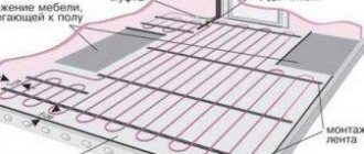
If one of the heating segments fails, the rest of the heated floor will still remain operational and will heat the room. Most often this happens when the laminate is laid incorrectly or the flooring is pushed through by the legs of heavy furniture. To repair, you will need to determine where the part of the floor that is not heating up is located, disassemble the laminate and completely replace the failed graphite tape.
If the supply wire breaks, you will need to disassemble the covering and solder the wire, as is the case with cable floor heating.
Types of temperature controllers
Thermostats for such heaters are made to be quite compact (no larger than a light switch) and aesthetically pleasing. At the same time, there are models both built-in and overhead, as well as for installation on a DIN rail. Some of them are equipped with a built-in sensor. Such options are preferable when the heating floor is the main source of heat, although they also have connectors for connecting an external temperature sensor. In other cases, a remote resistance thermometer is required.
In addition, thermostats can be divided into three conditional groups:
- Electromechanical ones are the simplest and cheapest prototypes, which are based on a mechanical principle of operation with an electrical component. Such regulators have few functions and settings: an on/off key, a wheel or knob for setting the temperature, and an LED indicating whether heating is currently occurring.
- Electronic ones are almost no different from the previous ones, except that they are equipped with a digital display and, therefore, an electronic temperature sensor. Their adjustment accuracy is better, but the cost is higher.
- “Smart” thermostats are the most preferable option. These are truly “smart” and functional programmers, capable of not only maintaining a given temperature, but also allowing you to set the mode in a convenient way. So, they can turn on and off themselves at a given time, and lower the temperature at night. Moreover, the program allows you to change the temperature not only depending on the time of day, but also to adapt to the wishes of the owner. Let’s say that in the morning the floor warms up, and when you leave the house, the minimum temperature will be maintained, and by the time the owner returns, the floor (and the room) will be heated to a comfortable level. On weekends, the regulator will operate according to a different specified algorithm. This is not only convenient, but also allows you to save a lot of energy. Some models can be equipped with a remote control or even controlled remotely via the Internet or mobile communications.
However, models are also produced that are capable of regulating and controlling the temperature in adjacent rooms. To do this, they are equipped with additional inputs for temperature sensors and additional outputs for the heater.
Thermostat connection diagram: