Before the development of microprocessor technology, various relay systems were used to protect substations with voltages above 1000 volts. They consumed a huge amount of energy for their own needs, were difficult to set up and were not reliable. Today, this task is performed by logical bus protection systems built on electronic components.
Protection and automatic input
Lzsh: operating principle, application for relay protection and circuits
Logical bus protection is currently included in almost any microprocessor relay protection terminal. Its task is to turn off a short circuit on the switchgear buses in the minimum possible time, limited only by the own response time of the electronic part of the terminal. Typically this is from 0.1 to 0.15 s.
Why is LZSh the most effective protection for this part of the reactor plant? Let's consider possible options for eliminating short circuits on tires.
The first option is to use differential protection. To implement it, additional windings of current transformers will be required at all connections of the section.
They need to be connected to a differential relay, the task of which is to add up the currents entering the buses from the power feeders and the currents at the outgoing connections at the moment of a short circuit.
If the unbalance current exceeds the set value, the relay gives a shutdown command.
The system turns out to be very complex, but with complexity its reliability decreases.
In addition, current transformers with additional windings are more expensive. Restrictions are imposed on testing relay protection and automation connections: if a test current is accidentally supplied to it, the protection will operate falsely.
The option of using incomplete differential bus protection is also not very effective.
It differs from the previous one in that current transformers are used only for supply lines and powerful consumers. But its use, among other things, is very limited.
The next opportunity to protect buses is overcurrent protection of supply lines. In principle, this is done in the vast majority of cases. But this type of protection has a significant drawback. To detune the MTZ from short circuits at outgoing connections, its time delay must be greater than that of the MTZ of consumers. In practice this is 1 – 3 seconds.
As the short-circuit current increases, every second of its action becomes fatal for electrical equipment. The longer the arc burns, the more destruction it causes.
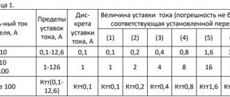
Current settings are set when programming BMRZFKS
-minimum voltage protection (MVP);
- quasi-thermal protection of the feeder;
-reservation in case of circuit breaker failures (breaker failure);
-logical bus protection (LZSh);
- double automatic reclosure (AR);
- protection of the adjacent feeder of the contact network (current cut-off and second stage of emergency protection).
To protect DPR feeders, BMRZ-FPE were used, which made it possible to:
- current cut-off; three-stage MTZ, with the first two stages having an independent time delay, and the time delay of the third stage can be either dependent or independent to choose from;
— minimum voltage protection;
-LEVEL;
-logical bus protection;
- double automatic reclosure.
Other protections included in MT BMRZFPE (zero sequence protection, etc.) are not used.
On 27.5 kV input switches, MT BMRZFVV is used, containing:
-two-stage MTZ with voltage blocking;
-two stages of DZ (“keyhole”);
-minimum voltage protection;
— Breaker failure failure with the possibility of switching on an output relay in the relay protection and automation circuit of the high voltage side of the power transformer;
-logical bus protection;
- protection against recharge short circuits on the high voltage side from adjacent substations through the contact network.
What does LZSH consist of?
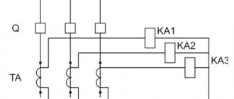
Bus logic protection elements are not concentrated in one place. This is a system that combines protection terminals for supply and outgoing lines.
Outgoing lines, when launching their own protections (usually MTZ), generate a blocking signal LZSh. For this purpose, one discrete output is allocated to each of them. Signals from all outgoing lines of the section are sent to the discrete inputs of the power feeder terminals. For transmission, a power and control bus system is used, which is part of any modern switchgear. This is where the entire constructive part ends. All that remains is to set the correct LZH settings on all terminals and set the assignment of discrete inputs and outputs.
The terminals of the section switches receive the LZSh blocking signal from the connections of both sections that they connect. For this purpose, different digital inputs are used.
LZSH organization schemes
Behavior of LZSh during external short circuit
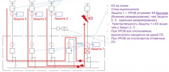
In the event of an external short circuit, the overcurrent protection of the connection at which it occurred is triggered. Naturally, the shutdown will occur after the time delay specified for the given fault current has expired.
But, if there is a LZH, the terminal will perform one more task: it will issue a signal to block it.
It will arrive at the terminals of the feeders feeding the section.
On these terminals, if the MTZ is triggered, the LZSh will start. It is in them that it is configured to turn off; on outgoing elements it is not needed, their task is only to transmit a signal that the short circuit is in their coverage area, and they are ready to eliminate it.
The appearance of a blocking signal will cause the LZSh at the supply line terminals to stop and shutdown will not occur.
In case of failure of the overcurrent protection of the outgoing line, the short circuit will be eliminated by the overcurrent protection of the supply feeder or breaker failure. LZSH is not responsible for refusal.
Operation of LZSh during short circuit on tires
If a short circuit occurs on the switchgear buses, no blocking signal will be received from the outgoing lines, since the short circuit current does not pass through them.
The launch of the overcurrent protection of the supply bus lines in the absence of a blocking signal will lead to an instantaneous action of the LZSh to disconnect the connections.
Moreover, all switches through which power is currently supplied will turn off independently of each other. If, in addition to the input, a sectional switch is turned on, then the LZSh will work on it as well.
The protection is called logical precisely because its work is associated with the analysis of the location of the short circuit in the system: if not a single terminal of the outgoing line sees the short circuit, then it is on the buses.
The area covered by the protection is limited to the installation sites of current transformers of all connections of the section. In this way, it is similar to differential bus protection, implemented in a classical way. When the LZSh is triggered, an ATS prohibition signal is generated for the damaged section.
Reliability of LZSh
Unlike other protections, LZSh rarely trips when checking relay protection and automation equipment by electrical laboratory personnel.
When working on outgoing connections, the blocking signal, although it arrives at the inputs of the power line terminals, does no harm.
Diagnostics of circuits for open circuits using current flow
Let's return to discrete circuits in which the redundant information method cannot be used. These are all input circuits with single contacts, switches and buttons on the plus side of the operas. current
If you can pass a small fixed current through such a circuit, then open monitoring becomes feasible. True, creating such a circuit is not easy, and the design itself does not inspire confidence among relay makers (see figure below)
Knowing the tension of the opera. current and the value of the resistor R shunting the contact, you determine the circuit control current. A sharp increase in current in the circuit means the contact is closed (working in accordance with the main algorithm), and the disappearance of the control current Ik means an open circuit.
The disadvantages of this scheme are obvious: an internal power supply for the circuits and a current analysis circuit in each discrete input of the terminal are required. And installing resistors in parallel with each external NO contact is a rather boring task. Therefore, in reality, the circuit is used infrequently, although devices with an internal power supply for discrete inputs are on the market.
What is relay protection and why is it needed?
You are here: In accordance with the requirements of the rules of technical operation of electrical installations (abbreviated PTE), power equipment of electrical networks, substations and power plants themselves must be protected from short-circuit currents and failures of normal operation. Special devices are used as protective equipment, the main element of which is a relay.
Actually, that’s why they are called that – relay protection and electrical automation devices (RPA). Today, there are many devices that can quickly prevent an accident in the serviced section of the power grid or, in extreme cases, warn personnel about a violation of the operating mode.
In this article we will look at the purpose of relay protection, as well as its types and design.
What is it for?
First of all, we’ll tell you why you need to use relay protection. The fact is that there is such a danger as the occurrence of a short-circuit current in the circuit. As a result of a short circuit, conductive parts, insulators and the equipment itself are very quickly destroyed, which entails not only the occurrence of an accident, but also an industrial accident.
In addition to a short circuit, overvoltage, current leakage, gas release due to decomposition of oil inside the transformer, etc. may occur.
In order to promptly detect danger and prevent it, special relays are used that signal (if equipment failure does not pose a threat) or instantly turn off the power in the faulty area. This is the main purpose of relay protection and automation.
Basic requirements for protective devices
So, in relation to relay protection and automation the following requirements are imposed:
In simple words, the purpose of relay protection and the requirements for it are that the devices must monitor the operation of electrical equipment, respond in a timely manner to changes in the operating mode, instantly disconnect the damaged section of the network and alert personnel about an accident.
Relay classification
When considering this topic, one cannot help but dwell on the types of relay protection. Relay classification is presented as follows:
As for the types of relay protection systems themselves, there are many of them. Let’s immediately look at what types of relays there are and what they are used for.
Separately, I would also like to consider the types of electrical automation, the purpose of which, unlike relay protection, is, on the contrary, to turn the power back on. So, in modern relay and automation systems they use the following type of automation:
In addition, there are the following types of automation:
So we looked at the purpose and areas of application of relay protection. The last thing I would like to talk about is what the relay protection consists of.
Relay protection and automation design
The relay protection device is a circuit consisting of the following parts:
Finally, we recommend that you watch a useful video on the topic:
Relay protection and automation in the energy sector for beginners
That's all we wanted to tell you about the purpose of relay protection and the requirements for it. We hope you now know what relay protection and automation is, what its scope is and what it consists of.
It will be useful to read:
Relay protection and automation in the energy sector for beginners
Other related articles
What types of time relays are there?
Automatic transfer of reserve (ATS)
AVR is a basic automation for switchgear with several sections.
At the same time, you should not think that AVR is always done. There are simplified 10/0.4 kV transformer substations, in which the automatic transfer switch is usually done on the 0.4 kV side due to the fact that on the 10 kV side, to reduce the cost and simplify it, load switches are used and operate without transformers.
The ATS algorithm in modern terminals is usually distributed on input relay protection units. There are ATS options on 6(10) kV TN relay protection and automation units, as well as special ATS devices that contain only this algorithm and control three switches at once (for example, BMRZ-107-AVR and Sirius-AVR).
If you are interested in how a simple 6(10) kV automatic transfer switch works, then watch this video
The automatic restoration of normal mode (ANR) algorithm allows you to return the circuit to its original position without the participation of operating personnel, after the voltage at the disconnected input has been restored. It is not always used, often preferring to return the normal scheme manually.
We will continue our conversation about input protection in the next article, where we will consider the 6(10) kV input relay protection and automation at the substation.
The figure shows a 6(10) kV input protection and automatic terminal, type BE2502A03.
Developed by NPP EKRA, www.ekra.ru.
BE2502A03 contains all the protections listed in the article
Logical bus protection (LBP)
Today, logical busbar protection is an integral part of the relay protection and automation system for 6-35 kV switchgears.
Its spread was facilitated by the transition from electromechanical element base to microprocessor relay protection units. Just 15-20 years ago you would hardly have seen LZH in a project. The standard response time of a 6-10 kV overcurrent input is 1-2 seconds, versus 0.1-0.15 seconds for LZSh. The speed gain is obvious.
LZSh should be used with caution at substations with large 6-10 kV motors, which can feed an external short circuit with a current level sufficient to start the protection of connections and switchgear inputs. This can lead to false operation of the LPS with non-selective shutdown of the 6-10 kV section or blocking of the LPS in the event of a false start of connection protections.
Recently, in order to reduce the cost of projects, LZSh began to be used in ring networks with multilateral power supply (6-35 kV buses of substations, distribution centers, gas turbine power plants, etc.). For this purpose, the triggering elements of the protections are directed. This option must be comprehensively considered taking into account the reliability of the relay protection system and, in the case of particularly critical objects, preference should be given to differential busbar protection!
LZSH structure
LZS is distributed protection. It is not located in one specific terminal, but is distributed among the protections of inputs, CBs and outgoing connections (lines, transformers, motors, BSK, etc.).
Since the protection of 6-35 kV busbars is carried out by input and sectional switches, it is in the input and CB terminals that a breaking current stage (LCS) is implemented, operating with a minimum time delay (0.1-0.15 s).
The starting protection elements of downstream connections provide information about whether there is a short circuit at the connection, and if so, they close the output contacts of their terminal to transmit a signal to the input and CB terminals. This output signal is called “LZSh Block”.
Short circuit at the connection (outside the LZSh coverage area)
It is worth noting that despite the name, LZSh protects not only the buses themselves, but also the switch area. As with differential busbar protection, its coverage area is determined by the installation locations of current transformers.
That's all about the Basics of LZSH! Next time we’ll talk about possible schemes for implementing logical bus protection in real projects.
Fixing open circuits using relay reset
The idea is as old as relay protection and is reliable on the AK-47. You energize the relay coil or the internal circuit of the relay protection terminal, the guard contact opens and waits in the wings. If the power is lost or the circuit is broken, the contact returns to the closed state under the action of a spring. To fix the malfunction, you will need a circuit with adjacent operas. current, which are usually the central alarm circuits (see figure below)
To control the power supply of the terminal, you don’t even need additional elements because there is a “Failure” relay in each device (usually two contacts - for the central control system and the automated control system/TM). If you want to control all operational circuits, then you can hang an intermediate relay with a NC contact at the very end (KL in the figure). I don’t like such schemes because they look quite collective farm and increase the amount of equipment, but why not? Especially if the input signals are important
Controlled circuits: operational, power circuits
By the way, I would use the “Failure” relay even at a Digital Substation with diagnostics via GOOSE messages because through them it is not always clear whether a break has occurred or the terminal has failed. Although you can try to determine this by indirect signs
Bus logic protection circuits
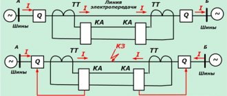
In this article we will talk about schemes for implementing logical busbar protection (hereinafter referred to as LPS) in 6(10) kV switchgear at direct operating current. The LZSh circuit can be constructed according to the scheme of parallel and serial connection of contacts of outgoing lines.
Let's consider a logical bus protection circuit with a series connection of contacts (Fig. 2). The block diagram of the 6(10) kV switchgear is shown in Fig. 1.
Fig. 2 – LZSh circuits according to the serial connection diagram
The principle of operation of the LZSh in a serial connection circuit is quite simple. If a short circuit occurs on the outgoing lines, their MTZ is triggered, thereby blocking the operation of the LZSh. In the event of a short circuit on the busbars, the MTZ of the outgoing lines do not start, the contacts are closed and the LZSH starts to operate. At this time, the input (sectional) switch is turned off with a minimum time delay.
This scheme has a number of disadvantages, namely: • with a large number of series-connected contacts, the reliability of the LZSh operation decreases; if one of the wires breaks, the LZSh fails. • it becomes more difficult to take out the outgoing line for repair; you have to put a jumper together where the LZSh contact is used, in order to avoid breaking the LZSh circuit.
Let us now consider the logical bus protection circuit with parallel connection of contacts (Fig. 3).
Fig. 3 – LZSh circuits according to a parallel connection diagram
This circuit is more reliable and has no disadvantages when connected in series. The principle of its operation is the same as with a serial connection.
Algorithm for fixing a break using redundant information
But what if you need to take the signal at “zero”?
This is a fairly common occurrence, for example, receiving a signal through the block contact of a switch. You need to determine the position of the switch both in the on and off state. Whatever BC you use at the time, it will be in the open position (at the input of the terminal or relay “hangs” 0)
For such cases, the option of redundant information is used, i.e. are connected immediately to two types of block contacts - normally closed and normally open, which are mechanically connected to each other (for example, located on the same drive shaft). At the same time, we can clearly detect an open pair circuit if there is no signal at two terminal inputs at once.
This is a classic task of monitoring drive circuits through relays/RPV/RPO inputs (see picture below, left side)
By the way, I have a detailed article on this topic.
Yes, gentlemen, relay operators, so that you don’t get bored - what element is missing in the RPV/RPO circuit for this implementation option? All sorts of block contacts for SF6 gas and springs, consider that I simply did not show them, but they seem to be there) Besides this, what is missing in the circuit? Write in the comments)
Another option for using this solution is monitoring operational blocking circuits, which are a big problem at substations (same picture, right side). Only instead of BC switches you use BC disconnectors. This method became popular with the advent of digital operational interlocking and allows you to reliably record a break in the signal circuits about the position of the knife.
Where else is the method of fixing a break using redundant information used? In principle, in all discrete circuits where we can get it. For example, to monitor the break of the LZSh blocking bus when connecting contacts in series
Yes, I wrote above that it is better to block LZH by “one”. But this is only true “if there is no way to confirm the signal!” Read the rule carefully)
The LZSh algorithm processes two logical signals at once - blocking the LZSh from downstream connections (opening the downstream protection contact) and starting its own overcurrent protection stage. If you assemble the LZSh locking busbar, as shown in the figure below, you will be able to detect the breakage of this busbar using a simple sign
This is the same principle as for RPV/RPO, but the connection between the logical signals is not so obvious. In electromechanics, you can assemble a similar circuit, but these principles became widespread precisely with the advent of MP RZA.
Controlled circuits: all except measuring circuits
Logical bus protection
Before the development of microprocessor technology, various relay systems were used to protect substations with voltages above 1000 volts. They consumed a huge amount of energy for their own needs, were difficult to set up and were not reliable. Today, this task is performed by logical bus protection systems built on electronic components.
Protection and automatic input
Relay protection and automation
Relay protection and automation is a system designed to protect a substation from emergency operation. It is a complex complex of electrical and electronic devices. Relay protection and automation continuously monitor the state of the network and, if necessary, make various switches in it.
Any RZiA has selectivity (selectivity). Those. it turns off exactly that section of the power system where an abnormal or emergency operation has occurred.
Accordingly, some consumers remain without voltage, and not all at once. This is especially necessary in cases where shutdown implies a violation of technical regulations.
processes of enterprises accompanied by the risk of emergency situations or financial losses.
Relay protection is also characterized by its speed. This property refers to the time spent disconnecting the damaged section of the line. Speed is closely related to selectivity. The setting for the permissible time for an emergency to occur is taken into account in the settings of the relay protection and automation terminal, and it determines on which section the line will be separated from the general system.
Additional Information. The speed of protection is its most important characteristic. For proper tuning you need a golden mean. If the time delays are chosen so that they are too short or long, then the system will disconnect lines that do not need it, i.e. False positives will occur.
What does LZSH consist of?
Answering the question “What is LZSh protection?”, we can say that it includes a complex set of hardware and software designed to disconnect the line during abnormal operation. All of them can be divided into 3 categories:
Simplified, it all works as follows. Some emergency situation occurs on the substation buses, for example, a short circuit. Current transformers register a critical excess of this parameter.
From them the signal is transmitted to a microprocessor terminal, which processes it. This takes into account the short circuit current, its duration and a number of other characteristics.
Then the terminal sends a signal to the actuator - a vacuum switch, which disconnects the section of the line affected by the short circuit.
LZSH organization schemes
Most logical bus protection systems are implemented in a serial or parallel circuit. Each of them has its own advantages and disadvantages, but the principle of operation of the LZSh is similar in both cases.
In a series circuit, the individual contacts follow each other. While all of them are closed, a signal is sent to the LZSh blocking input, preventing the protection from triggering. If at least one contact of the relay terminal opens, the overall circuit will be broken.
Sequential LZSh circuit
In the case of a parallel circuit, the contacts are initially in the normally open position. For the LZS to operate, it is also necessary that one of them changes its state, i.e. closed up.
Behavior of LZSh during external short circuit
Overcurrent protection
The operating principle of logical bus protection is based on cutting off the line when a short circuit current occurs in it. In this case, it is assumed that the short circuit occurred somewhere outside the substation.
While the line is in normal operating mode, the LZSh contacts generate a blocking signal. It prevents the protection from tripping, so the system is energized. As soon as a short circuit or serious overcurrent occurs, the LZSh contacts open. The protection is turned on.
The calculation of the line shutdown time directly depends on the intensity of the short circuit and the settings made by the installer in the relay protection and automation terminal.
Additional Information. Intermittent short circuits are possible on overhead power lines. They can be caused by overlapping wires due to wind. In this case, the short circuit is short-term; after it disappears, the line is put back into operation by an automatic reclosure device (AR).
Operation of LZSh during short circuit on tires
Another purpose of using LZSh is to cut off the voltage when a short circuit occurs on the busbars. In this case, we are talking about a short circuit that occurs directly on the territory of a switchgear or substation. This situation has a peculiarity.
The short circuit occurs in the immediate vicinity of the transformer. The tire resistance up to the short circuit point has a minimum value. The fault current will be extremely high, up to tens of thousands of amperes.
The RZiA terminal, registering such a large value, will assemble a chain of LZSh faster than if the accident had formed somewhere far from the substation. If for some reason this protection cascade does not work, then the power will be turned off by the one that is higher in the chain.
In this case, the entire section will be out of work. The response will be non-selective, which is undesirable.
Diagnostics of current circuits
The peculiarity of current circuits is that there are no events in them (the appearance or disappearance of a significant signal). Measurements are carried out continuously, regardless of the presence of damage in the primary network. Most of the time there is an intermittent signal present in these circuits, which does not give you meaningful information to diagnose an open. And even if the signal disappears, this does not necessarily mean a break. Perhaps the network load has simply dropped to zero.
Thus, it is almost impossible to check a single current circuit for an open circuit. Of course, now you will write to me 100,500 relatively honest ways to monitor such circuits (such as measure the current I2, compare with I1), but in practice, for step protections, monitoring for broken current circuits is not used. Here, a Digital substation can really give a head start to a conventional one.
Another thing is differential protection, where, in the absence of damage “in the zone,” the current in the protection is always approximately zero. If you can select a setting for the current circuit diagnostic algorithm that is lower than the maximum unbalance current, but higher than the initial setting for the triggering of the current circuit breaker, you will be able to detect open circuits. This is what is done in practice, both in microprocessor-based relay protection and automation systems, and in circuits with electromechanics.
From the book “Differential protection of buses 110-220 kV”. I.R. Taubes. BE. 1984
For example, in DPS circuits, the setting for the start of the response characteristic is selected higher than the operating current of the most loaded connection. If any current circuit breaks, an alarm is triggered and the motor protection device is taken out of operation. This is done so that there is no false shutdown during an external short circuit. Then you have some time to search for a break and restore the normal circuit.
By the way, with the advent of relay protection and automation terminals with a second group of current inputs, for core 0.5, it became possible to control current circuits using redundant information, similar to discrete ones.
At the same time, the number of electronic devices that perform almost the same functions will decrease. True, relay and dryer specialists may have questions about combining functions in one device. And then the telemechanics service will catch up)
Relay protection. Types and device. Operation and features
According to the rules for the operation of electrical installations, power devices of electrical networks and power plants must be provided with protection against operational failures and short circuit currents. The means of protection are special devices made on the basis of relays, which justifies their name relay protection and automation (RPA). Currently, there are many different devices that can quickly block an emergency in the electrical network, or give a warning signal about the occurrence of an emergency mode.
Relay protection most often works in conjunction with automation, and their design is interconnected with specific types of network emergency modes:
Types of relay protection
Relays are classified according to certain criteria:
Relay protection and automation come in various types:
Some types of automation are designed to supply electricity, as opposed to relay protection:
Relay protection. Device
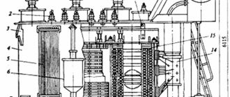
Electromechanical relay protection designs are constantly being modernized and improved. Innovative technological developments and projects are being introduced. The latest energy systems combine static, induction, electromagnetic devices with microprocessor and semiconductor elements.
However, the basic meaning and operating procedure of relay protection for all new devices remains unchanged. The relay protection structure diagram is shown in the figure.
1 — Electrical signal 2 — Electrical process monitoring block 3 — Logic and analysis block 4 — Execution block
5 - Signal block
Observation unit
The main function of this unit is to monitor the electrical processes occurring in the electrical system by measuring devices such as voltage and current transformers.
Output signals on the block can be sent directly to the logic block to compare parameters with user-configured deviation values, called setpoints. Also, the signals from the surveillance unit can first be converted into digital form and then transmitted further.
Logic block
In this block, the received signals are compared with the limiting setpoint values. Even a slight coincidence of these parameters leads to a command to trigger the protection.
Executive block
This block is always in a state ready to operate when a command is received from the logic block. When triggered, the electrical installation circuit is switched according to a planned algorithm, which is based on the principle of preventing electrical equipment malfunctions and electric shock to workers.
Signal block
In the electrical system, all processes occur very quickly, so a person is not able to perceive them. To save events occurring in the system, special signaling devices are used. Which work by sound and visual notification, and also save all occurring events in the device’s memory.
All types of devices, after they are triggered, are manually reset by the operator. This allows you to reliably save information about the operation of automation and relay protection.
Work principles
Relay protection may have disturbances in its performance, which are expressed by the following factors:
To eliminate failures during the operation of relay protection, special requirements are developed for it during design, installation, configuration with commissioning, and maintenance:
Reliability principle
This principle is defined:
Each of these factors has its own assessment.
Maintenance and operation of relay protection has three options for reliability when triggered:
The reliability of protection devices is:
Sensitivity principle
This principle makes it possible to determine the types of expected design damage and abnormal modes of the energy system in the working protection zone.
Kch = Iкз min/Iсз
To determine its numerical value, the Kch coefficient is used. The coefficient is calculated by the ratio of the smallest short-circuit current of the working area to the magnitude of the operating current. Relay protection operates in normal mode when:
Iсз https://electrosam.ru/glavnaja/jelektrooborudovanie/rozetki-vykljuchateli/releinaia-zashchita/
Introduction
Today, electricity occupies a special position. Its exceptional qualities, such as the possibility of transformation and easy conversion into other types of energy: thermal, mechanical, have led to today's widespread development of electric power systems (EPS). Today, the production, delivery and distribution of electrical energy is carried out by many services: energy production, operational services, distribution network dispatch services, electrical equipment repairers and others. It should be noted that the delivery and distribution of electrical energy has a number of distinctive features that are not characteristic of other industries. For example, the instantaneous propagation of electric current, as well as the ability to transfer huge amounts of energy (at high voltage) can lead to extreme consequences in the event of an accident. That is why EPS places a special emphasis on providing protection.
Today, many concepts have been developed for protecting lines, devices and network sections from the occurrence of abnormal conditions, the most dangerous of which are Short Circuits (SC). In addition to protection systems, monitoring network parameters in individual sections, as well as operational remote control of switching equipment, is also of particular importance. Telemechanics and measurements, along with protection from abnormal conditions, are usually also the area of responsibility of the relay protection service, usually called the Relay Protection, Automation and Measurement Service (RPAI)[2].