1. Definition
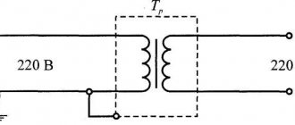
A voltage boost transformer (VDT) is a device consisting of two transformers: a series transformer, the primary winding of which is included in the line cut, and a special control transformer or autotransformer with a variable transformation ratio. The regulating autotransformer is powered from the low voltage winding of the power transformer.
A linear regulator is a three-phase voltage booster device that operates according to an autotransformer circuit.
What is voltage drop
To put it simply and to make it clearer, this is energy (and active!) released in the form of heat.
Let me give you an example. For each wire cross-section there is a maximum allowable current. If to a copper wire with a cross-section of 2.5 sq. mm connect a single- phase electric body with a power of 9 kW with a current consumption of 9000:220 = 41 amperes, then the wire will get very hot.
The material from which the wire is made, copper, actively resists electric current.
Purpose
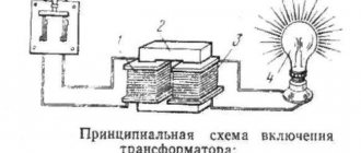
Voltage booster transformers (linear regulators) are used to regulate voltage in individual lines or in a group of lines. They are used, for example, to improve the operation of networks that use transformers without load regulation. Linear regulators allow you to create an additional EMF in the network, which adds up to the network voltage vector and changes it. In Fig. Figure 1 shows a schematic representation of a boost transformer (linear regulator).
Figure 1 – Schematic representation of a linear regulator
Installing a voltage booster transformer allows you to equalize the voltage in the electrical network; eliminate voltage asymmetry in a certain section of the circuit; reduce the dangerous consequences of burning out the neutral conductor
On-load tap-changer tank jet protection
110 kV power transformers usually have a built-in on-load voltage regulation device (OLTC).
The on-load tap-changer is located in a separate compartment of the transformer tank, isolated from the main tank with windings. a separate protective device is provided for this device .
All damage inside the on-load tap-changer tank is accompanied by the release of transformer oil into the conservator, therefore, in the event of an oil flow, the jet protection is instantly activated, automatically disconnecting the power transformer from the electrical network.
Repair of switching devices (transformer on-load tap-changer)
When repairing switching devices without excitation ( PVB ), carefully inspect all contact connections of the switch and taps; determine the tightness of the contacts by checking the gap between the lamellas with a feeler gauge; measure the transient electrical resistance.
Particular attention is paid to the condition of the contact surface.
If there are burns or melting, the device is replaced (depending on the nature or extent of damage, the device is sometimes restored).
To remove deposits formed when working in oil, the contact part of the switch is thoroughly wiped with a technical cloth soaked in acetone or gasoline. The rest of the device is washed with clean transformer oil.
When repairing load control switching devices (OLTC), in addition to general work on cleaning, wiping and rinsing the external and internal surfaces of parts and parts of the device, the contact surfaces of the stage selector, contactors and the electrical part of the drive mechanism are checked. The burnt contacts of the selector, the main contacts of the contactor and the drive are carefully cleaned and checked for tightness, after which the cause of the burn is determined and eliminated.
Failure of the switch drive can be caused by moisture ingress due to poor sealing of the cabinet door, as well as due to significant play in the connecting shafts. Identified defects are eliminated. Remove sediment remaining after draining the oil from the bottom of the contactor tank, and also perform other work in accordance with the operating instructions for the on-load tap-changer.
On-load tap-changer protection
To ensure normal operation of the device, gas protection is used. An additional container (expander) is made, connected to the main oil medium of the transformer by a special channel in which a relay and a signal element are installed.
If gas formation is slight, the signal element indicates a decrease in the oil level. In the event of a blowout, the expanded oil is forced into the conservator. If the surge intensity reaches the set value, the relay is activated, turning off the transformer. In this way, the on-load tap-changer contactors are protected from destruction.
Advantages and disadvantages of regulation using on-load tap-changers
The advantages of regulation without disconnecting the load are the ability to maintain network parameters at the output of the transformer at a given level when the characteristics of the supplied voltage change.
This device also allows you to adjust the parameters, taking into account the required value.
The specified functions are achieved without shutting down the unit.
The disadvantages are associated with the need to complicate the design of the transformer due to the use of additional elements.
At the same time, the reliability of the unit’s operation decreases, its weight and overall dimensions increase.
Video: Voltage regulation of power transformers
Video: Transformer with on-load tap-changer, operation diagram
On-load tap-changer of power transformer, principle of operation
Principle of operation
Booster transformers have one winding connected in series with the line in which the voltage is regulated. This winding is powered from a control (supply) transformer, and the primary winding of the latter is supplied from the network or an external current source. Depending on the connection diagram of the windings, booster transformers can create an additional EMF that is phase-shifted relative to the main voltage or coincides with it. In Fig. Figure 2 shows a schematic diagram of connecting a booster transformer.
Figure 2 – Schematic diagram of connecting a booster transformer
- main transformer
- series transformer
- control transformer
Features of regulators for primary transformers
The charging current of the battery is 10% of its capacity. This means that a 60 Ah battery is charged with a current not exceeding 6 A. The charging voltage when the vehicle is running is 14.5 V. Taking into account the required range, the charger should output 10 A at 16 V.
The voltage reserve is necessary to regulate and limit the charging current.
It is produced differently in different device models:
- Additional resistors. They light up after the diode bridge. The simplest design, but the largest.
- Transistor. High control accuracy, but the most complex circuit that requires good cooling of power transistors.
- Thyristor control. Simple diagrams. The adjustment is carried out by a thyristor switch in the primary winding circuit or by thyristors installed instead of diodes in the rectifier bridge.
Scheme and design
A more detailed diagram of a linear regulator, also illustrating the principle of switching contacts, is presented in Fig. 3. It shows the control transformer 1 and the series transformer 2. The primary winding 3 of the control transformer is the supply winding. It can be connected to both phase A - 0 and line voltage (A - B, A - C). The secondary winding 4 of the control transformer has the same switching device 5 as the transformer with on-load tap-changer.
One end of the primary winding 6 of the series transformer is connected to the midpoint of the secondary winding of the control transformer. The other is to the switching device. The secondary winding 7 of the series transformer is connected in series with the winding of the power transformer. The additional EMF in winding 7 adds up to the EMF of the power transformer and changes it.
Figure 3 – Operating principle of a booster transformer
In Fig. Figure 4 shows a three-phase circuit for connecting a booster transformer to the network.
Figure 4 – Scheme for connecting a voltage booster transformer to the network
Linear regulators operate according to an autotransformer circuit and are an oil-filled design that has six linear terminals for connecting the regulator to a line cut at any point. The connection diagram of the linear regulator is shown in Fig. 5.
- High voltage field winding
- Control circuit power winding
- Voltage booster winding
- Moving switch contact
- Auxiliary switch contact with active current-limiting resistance
- Fixed contacts
Figure 5 – Linear regulator connection diagram
What happens to a step-down transformer when the load increases
But nothing happens to him))) As he lowered the voltage, he continues to lower it - that’s how he’s designed.
110,000 Volts are supplied to the primary winding (high voltage winding), and 10,000 Volts are removed from the secondary (low voltage winding).
This is an ideal option when the voltage on the primary winding is stable and does not change, and the load on the secondary winding is either very small or nonexistent (the transformer operates in no-load mode).
In fact, this is not true at all.
In reality, the high voltage at the primary load is constantly changing within small limits - 110-117 kV
And since the transformation ratio of the transformer is constant, it turns out that on the 10 kV secondary winding the voltage also fluctuates, so to speak, “in step” with the primary voltage.
And after this, voltage fluctuations are transmitted to the next step-down transformers 10/0.4 kV...
And so these fluctuations will reach our apartments and the voltage would fluctuate in proportion to the high voltage of 110 kV.
And our sockets would have either 180 Volts or 250 Volts, and it would constantly change throughout the day. I think that no one will like it when the light in the house constantly changes brightness, as in that joke - it either goes out, then goes out, or doesn’t come on at all)))
Regulation range
The EMF created by a linear regulator depends on:
- on the value of the supply voltage;
- from the phase of the supply voltage;
- on the transformation ratio of the linear regulator.
By connecting the primary winding of the supply transformer to different phases of the network, you can obtain different voltages at the output of the regulator. In a linear regulator, phase-by-phase regulation is performed. There are longitudinal, transverse and longitudinal-transverse regulation.
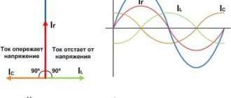
With longitudinal regulation, the additional EMF of the linear regulator ∆E is in phase with the phase voltages of the network. This type of regulation is also called modulo regulation.
With transverse regulation, the EMF of the power transformer and the additional EMF are shifted by 90º. Such a shift can be obtained if, for example, to regulate the voltage in phase A, the winding of the supply transformer is switched on to the linear voltage B-C. In this case, the resulting EMF of the winding of the power transformer and the secondary winding of the series transformer changes in phase. Therefore, this type of regulation is also called phase regulation. Longitudinal-transverse regulation allows you to adjust the initial voltage both in magnitude and in phase. It can be performed to regulate the voltage in phase A when the primary winding of the supply transformer is switched on to the line voltage A-B. The vector of additional EMF will be directed along the linear voltages.
Vector diagrams depicting different types of regulation are shown in Fig. 6.
Figure 6 – Voltage regulation using a linear regulator: a) longitudinal; b) transverse; c) longitudinally transverse.
Linear regulators with longitudinal regulation make it possible to regulate voltages in a problem area of an extended network or in the absence of an on-load tap-changer device on the transformer.
Linear regulators with transverse or longitudinal-transverse regulation perform narrower functions. With their help, the operating conditions of heterogeneous closed networks are improved.
Voltage regulation of power transformers
Greetings, reader of my website ceshka.ru!
In this article I want to tell you how the voltage of a 110/10 kV power transformer is regulated under load.
For those who are not at all in the subject, I’ll explain what we’re talking about.
Electricity from a power plant (nuclear power plant, thermal power plant, state district power plant, etc.) is transmitted through overhead line supports many hundreds of kilometers to a substation (I will talk about a 110,000 Volt substation), where step-down transformers are installed - very large and very powerful.
These transformers lower the voltage (in my example to 10,000 Volts) and transmit electricity further, but over a shorter distance - within 10-40 km to the next step-down transformer, which converts the already high voltage of 10 kV into a low three-phase voltage of 400 Volts, which and goes along the wires to our houses.
So, a 110/10 kV transformer installed at a substation is connected to a lot of load - it can be an entire rural area or part of a big city.
The workload changes throughout the day and throughout the seasons and changes greatly.
For example, in winter, many rural residents are heated by electric boilers , so the current consumed is much greater than in summer.
Or there are morning and evening hours of maximum load when people wake up or, on the contrary, come from work, turn on electrical appliances - electricity consumption increases greatly. During the day, the load decreases and sometimes even several times less than in the morning or evening.
Application
Linear regulators can be installed on outgoing lines and in series with a power transformer. When installing a linear regulator on outgoing lines, the power transformer stabilizes the voltage on the substation buses at an average level. The control range in this case can be reduced, which makes it possible to significantly reduce the power of the linear regulator, but the installation of several regulators is required.
In Fig. 7 a) shows a schematic representation of a linear regulator when it is connected in series with the winding of a power transformer, in Fig. 7 b) shows the activation of the linear regulator on outgoing power lines.
Figure 7 – Connecting a linear regulator to the network: a) in series with the winding of the power transformer; b) on outgoing power lines
Linear regulators, which are connected in series to the line, provide voltage regulation within ±10-15%. Linear regulators are widely used in substations with autotransformers. On the MV side, voltage regulation is provided by an on-load tap-changer built into the autotransformer, and on the LV side, a linear regulator equipped with automatic voltage regulation is installed.
TWO SIMPLE VOLTAGE REGULATORS
Once assembled, the simplest voltage regulator on one transistor was intended for a specific power supply and a specific consumer; of course, there was no need to connect it anywhere else, but as always, there comes a moment when we stop doing the right thing. The consequence of this is troubles and thoughts about how to live and be further and the decision to restore what was created earlier or continue to create.
Scheme number 1
There was a stabilized switching power supply that gave an output voltage of 17 volts and a current of 500 milliamps. A periodic change in voltage was required in the range of 11 - 13 volts. And the well-known voltage regulator circuit on one transistor coped with this perfectly. I added only an indication LED and a limiting resistor to it. By the way, the LED here is not only a “firefly” signaling the presence of output voltage. With the correct value of the limiting resistor, even a small change in the output voltage is reflected in the brightness of the LED, which provides additional information about its increase or decrease. The output voltage could be changed from 1.3 to 16 volts.
KT829, a powerful low-frequency silicon compound transistor, was installed on a powerful metal radiator and it seemed that, if necessary, it could easily withstand a heavy load, but a short circuit occurred in the consumer circuit and it burned out. The transistor has a high gain and is used in low-frequency amplifiers - you can really see its place there and not in voltage regulators.
On the left are removed electronic components, on the right are prepared for replacement. The difference in quantity is two items, but in terms of the quality of the circuits, the former and the one that was decided to be collected, it is incomparable. This begs the question: “Is it worth assembling a scheme with limited capabilities when there is a more advanced option “for the same money”, in the literal and figurative sense of this saying?”
Scheme number 2
The new circuit also has a three-pin electrical connection. component (but this is no longer a transistor) constant and variable resistors, an LED with its own limiter. Only two electrolytic capacitors have been added. Typically, typical diagrams indicate the minimum values of C1 and C2 (C1=0.1 µF and C2=1 µF) which are necessary for stable operation of the stabilizer. In practice, capacitance values range from tens to hundreds of microfarads. The containers should be located as close to the chip as possible. For large capacities, the condition C1>>C2 is required. If the capacitance of the capacitor at the output exceeds the capacitance of the capacitor at the input, then a situation arises in which the output voltage exceeds the input, which leads to damage to the stabilizer microcircuit. To exclude it, install a protective diode VD1.
This scheme has completely different possibilities. Input voltage is from 5 to 40 volts, output voltage is 1.2 - 37 volts. Yes, there is an input-output voltage drop of approximately 3.5 volts, but there are no roses without thorns. But the KR142EN12A microcircuit, called a linear adjustable voltage stabilizer, has good protection against excess load current and short-term protection against short circuits at the output. Its operating temperature is up to + 70 degrees Celsius, works with an external voltage divider. Output load current is up to 1 A during long-term operation and 1.5 A during short-term operation. The maximum permissible power when operating without a heat sink is 1 W, if the microcircuit is installed on a radiator of sufficient size (100 cm2) then P max. = 10 W.
What is a triac
The thyristor has a drawback that complicates its use in an alternating current network: only a half-wave passes through itself, and the output produces a constant ripple instead of an alternating voltage. Therefore, these devices are used in pairs or together with a diode bridge. The triac is free of this drawback.
A triac is similar to a thyristor. Like a thyristor, it is opened by a pulse of current flowing through the control electrode, but this device passes both half-waves through itself and is capable of operating in an alternating current network.
Schematic diagram of a triac current regulator for active and inductive loads. The design of a triac regulator is similar to a thyristor regulator. The difference is that the triac controls both polarities, and therefore there is no need to use a diode bridge or back-to-back connection of elements.
In addition, the polarity of the control voltage does not matter for the triac, which simplifies the pulse control circuit.
Advice! To adjust the triac, you can use a dimmer from an incandescent lamp. To do this, it is connected between the anode and the control electrode of the power triac.
Other simple options for adjusting the voltage in the primary
In addition to thyristor and triac regulators, there are other ways to control the charging current in the primary winding of a transformer:
- By switching the terminals of the primary winding. The disadvantage is that these conclusions have to be made when winding the coils.
- Connecting the charger after LATRA (laboratory autotransformer). Its power must be at least 160W.
- A variable resistor connected in series to a transformer. Its parameters are about 50-100 Ohms, with a power of 50 W and depend on the specific charger.
Despite the advent of modern chargers, many car owners have devices with conventional transformers, and setting up the device through the primary winding allows you to do without powerful thyristors or additional resistors.
. The proposed universal design is designed for charging 12 and 6 volt acid batteries and is capable of providing a charge current of up to 5-6 A. The current adjustment is smooth. Unlike conventional circuits, in this design the control element (thyristor VS1) is included in the primary winding circuit, which significantly reduced the power dissipated on it and made it possible to do without installing a thyristor on the radiator. The control circuit installed on comparator PA1 is also quite inexpensive, since it does not have a powerful shunt, which is usually included in the secondary circuit. Let's take a look at the circuit diagram of the charger.
Since the control element is a thyristor, which cannot operate with alternating current, it had to be included in the diagonal of the bridge assembled on diodes VD1 - VD4. The current through the primary winding (and therefore the charging current) is regulated by changing the opening angle of the thyristor - this is controlled by a control unit assembled on a unijunction transistor VT1.
When the resistance of variable resistor R6 changes, the charging time of capacitor C1 also changes. The longer the capacitor takes to charge, the later the transistor and therefore the thyristor opens after the start of the mains voltage period. Thus, the current through the primary winding of transformer T1 can be smoothly adjusted from 0 to almost 100%. In this case, the voltage on the secondary winding of the transformer will vary from 0 to 18-20 V, which will cause a change in the battery charging current.
The charging current is controlled indirectly by measuring the current through the primary winding using a comparator PA1 connected through a ballast resistor R2 and deflected by a two-watt resistor R1. Lamp HL1 is a signal lamp.
In the project, in addition to those indicated in the diagram, diodes D231 - D234, D245, D247 with any letter index, KD202 with the letters K, M, R can be used. They cannot be installed on heating radiators. Thyristors KU201K, L, KU202K, L, M, N will work like VS1. The thyristor also does not need a radiator. In the secondary circuit (instead of VD5 - VD8), in addition to those indicated in the diagram, D231 - D233 will work without a letter index or with the letter A. They must be installed on radiators with an area of at least 30 cm2 each (if the diodes are germanium - D305), or a square 100 cm, if silicon.
Capacitor C1 must have a minimum temperature coefficient of capacitance, for example, type K73-17, K73-24. Otherwise, when the device heats up, the charging current “turns off”. Like T1, any network transformer with a power of at least 150 W is suitable, capable of supplying a voltage of 18-20 V from the secondary winding with a current of up to 6-7 A. It is very convenient for these purposes to use standard TN or TAN transformers, the characteristics of which can be found in our handbook on transformers. Any microammeter with a total deviation current of 100 μA can be used as a PA1 meter.
Setting up the device comes down to selecting the resistance value R2 to calibrate the PA1 device while simultaneously monitoring the charging current. Perhaps the only drawback of such a charger is the presence of mains voltage on the control circuit, therefore, for safety reasons, it is necessary to place a handle made of insulating material on resistor R6.
A. Evseev “Electronic devices for the home”, 1994
Attention! The design has a transformerless power supply, so during operation, life-threatening voltage is present on all its elements. Before any welding or circuit modification, be sure to unplug the structure!