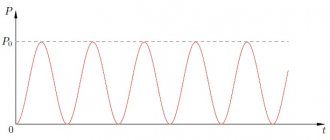
In previous articles, we learned that any resistance that absorbs energy is called active, and resistance that does not absorb energy is called wattless or reactive. In addition, we have established that reactances are divided into two types - inductive and capacitive.
However, there are circuits where the resistance is not purely active or purely reactive. That is, circuits where, together with active resistance, both capacitance and inductance are included in the circuit.
Let's introduce the concept of circuit impedance to alternating current - Z , which corresponds to the vector sum of all circuit resistances (active, capacitive and inductive). We need the concept of circuit impedance for a more complete understanding of Ohm's law for alternating current
Figure 1 shows options for electrical circuits and their classification depending on which elements (active or reactive) are included in the circuit.
Figure 1. Classification of AC circuits.
The total resistance of a circuit with purely active elements corresponds to the sum of the active resistances of the circuit and was considered by us earlier. We also talked about the purely capacitive and inductive reactance of the circuit, and it depends, respectively, on the total capacitance and inductance of the circuit.
Let's consider more complex circuit options, where inductive and reactive reactance are connected in series with active resistance.
Electrical circuit.
A source of electric current connected by wires to various electrical appliances and consumers of electrical energy forms an electrical circuit.
It is customary to depict an electrical circuit using diagrams in which the elements of the electrical circuit (resistances, current sources, switches, lamps, devices, etc.) are indicated with special icons.
The direction of current in a circuit is the direction from the positive pole of the current source to the negative pole. This rule was established in the 19th century. and has been observed ever since. The movement of real charges may not coincide with the conventional direction of the current. Thus, in metals, current carriers are negatively charged electrons, and they move from the negative pole to the positive one, that is, in the opposite direction. In electrolytes, the actual movement of charges may coincide with or be opposite to the direction of the current, depending on whether the ions are charge carriers - positive or negative.
The inclusion of elements in an electrical circuit can be serial or parallel.
Links[edit]
- Callegaro, page 2
- Callegaro, Sec. 1.6
- Science
, page 18, 1888 - Oliver Heaviside, The Electrician
, p. 212, 23 July 1886, reprinted as
Electrical Papers, Volume II
, p. 64, AMS Bookshop, ISBN 0-8218-3465-7 - Kennelly, Arthur. Impedance
(AIEE, 1893) - Alexander, Charles; Sadiku, Matthew (2006). Basics of electrical circuits
(3, revised). McGraw-Hill. pp. 387–389. ISBN 978-0-07-330115-0. - Complex impedance, Hyperphysics
- Horowitz, Paul; Hill, Winfield (1989). "1" . The Art of Electronics
. Cambridge University Press. pp. 31–32. ISBN 978-0-521-37095-0. - AC Ohm's Law, Hyperphysics
- Horowitz, Paul; Hill, Winfield (1989). "1" . The Art of Electronics
. Cambridge University Press. pp. 32–33. ISBN 978-0-521-37095-0. - Parallel impedance expressions, Hyperphysics
- ^ a b
George Lewis Jr.;
George C. Lewis Sr. and William Olbricht (August 2008). "Cost-Effective Wideband Electrical Impedance Measurement Circuit and Signal Analysis for Piezo Materials and Ultrasonic Transducers". Measurement Science and Technology
.
19
(10): 105102. Bibcode: 2008MeScT..19j5102L. DOI: 10.1088/0957-0233/10/19/105102. PMC 2600501. PMID 19081773.
What is resistance
Current flowing through wires and various radio components wastes its energy. This phenomenon is quantitatively expressed by the magnitude of the resistance. In electrical engineering, it is divided into active and reactive resistance. In the first case, when a current passes, part of its energy is converted into a thermal form, and sometimes into others (for example, it manifests itself in chemical reactions). The value of active resistance depends on the frequency of alternating electric current and increases with its increase.
The second type of resistance has a more complex nature and occurs when a consumer of electricity is turned on or off in an AC or DC network. In a circuit with reactance, the energy of the electric current is partially converted into another form, and then transferred back, that is, a periodic oscillatory process is observed. Circuit impedance includes active and reactive types, which are taken into account according to special rules.
See also[edit]
- Bioelectrical impedance analysis
- Characteristic impedance is the ratio of the voltage and current amplitudes of a single wave propagating along a transmission line.
- Electrical characteristics of dynamic loudspeakers
- High impedance
- Immitance
- Impedance Analyzer
- Bridge resistance
- Impedance Cardiography
- Impedance control
- Impedance matching
- Impedance microbiology
- Negative impedance converter
- Resistance distance
- Transmission Line Impedance - Signal Phenomenon
- Universal dielectric response
Types of resistance
In electrical engineering, active electrical resistance is considered, as well as two types of reactive resistance: inductive and capacitive.
Active resistance You can imagine an electrical circuit in which a resistor and a light bulb are connected in series to the battery terminals through a wire. If you short the wires, the light will light up. You can use a voltmeter or multimeter in the appropriate operating mode, which measures the potential difference between two points in the circuit.
By measuring the voltage between the terminals and comparing it with that on the wires connected to the light bulb, you can see that the latter is less. This is due to a voltage drop across the radio component soldered into the circuit. The latter counteracts the electric current, making it difficult to pass.
Each part through which current passes has active resistance. For metal wires it is very small. To find out the resistance value of a radio component, you need to study the designation on its body. If a resistor is removed from the electrical circuit in question, the current passing through the light bulb will increase.
The formula for calculating active resistance corresponds to Ohm's law:
R = U / I, where
- R is the value of active resistance between two points in the circuit;
- U is the voltage or potential difference between them;
- I is the current strength in the section of the circuit under consideration.
To calculate the active resistance of the conductor, the formula will be different:
where K is the surface effect coefficient, which is equal to 1,
- l is the length of the conductor,
- s is the cross-sectional area,
- p - “po” resistivity.
Resistance is usually measured in Ohms. It significantly depends on the shape and size of the object through which the current flows: cross-section, length, material, as well as temperature. The action of active resistance reduces the energy of electric current, converting it into other forms (mainly heat).
Reactance
This type occurs when alternating current passes through an element that has inductance or capacitance. The main feature of reactance is the conversion of electrical energy into another form in the forward and reverse directions. This often happens cyclically. Reactance only appears when current and voltage change. There are two types: inductive and capacitive.
Inductive reactance
As the current increases, a magnetic field with different characteristics is generated. The most important of these is inductance. The magnetic field, in turn, affects the conductor through which current flows. The effect is opposite to the direction of current change. That is, if the current strength has increased, then the magnetic field will reduce it, and vice versa, if it has decreased, then the field will strengthen it. When the current does not change, the reactance of the inductor will be zero.
Inductive reactance depends on the frequency of the current. The higher it is, the higher the rate of change of this parameter. This means that a stronger magnetic field will be generated. The resulting EMF prevents a change in the electric current.
The calculation of inductive reactance is carried out using the following formula:
XL = L×w = L×2π×f, where the letters indicate:
- L is the inductance of the magnetic field, which is generated by a change in current strength;
- W is the circular frequency of change, which is used in describing the sinusoidal change in current strength;
- Π—pi number;
- f is the current frequency in the usual sense.
With a sinusoidal change in voltage, the current strength will change, falling behind it in phase. Therefore, the reactance of a transformer depends significantly on its inductance.
Capacitance
It has a different nature than inductive. It is convenient to illustrate this concept using the example of an electrical circuit consisting of a power source, the terminals of which are connected to the plates of a capacitor. Immediately after connection, a charge will gradually accumulate on them, creating a current in the circuit.
After reaching the limit value, which is determined by the capacitance of the part, the current will not flow through the circuit. If you then disconnect the wires from the terminals and then connect the latter, then charges will begin to move between them until the potential difference becomes zero.
If you connect an AC source to the capacitor, the following will happen. As the potential difference increases, the charge on the capacitor plates will increase. When the voltage enters the decreasing phase, the accumulated charge will begin to drain from them, forming a current in the opposite direction. Then the potential difference will become negative, but in absolute value it will increase to its maximum value. In this case, the capacitor will begin to charge again, but the sign of the incoming charges will not be the same as it was before.
When the voltage begins to increase (decreasing in absolute value), the charge will drain from the capacitor plates. When the potential difference at the source reaches zero and continues to increase, a new cycle of changes will begin.
At each stage of the described situation, the current from the capacitor plates will have the opposite direction to that generated by the variable potential difference of the power source.
The decrease in current that occurs in this way represents the physical meaning of capacitance. It is denoted by the letters XC and is calculated using the formula:
XС = 1/(w×C) = 1/(2π×f×C), where
- C is the capacitance of the capacitor used;
- w is the circular frequency of alternating current;
- π—pi number;
- f is the frequency of alternating current.
In the case under consideration, changes in current lag behind voltage.
Impedance
When using several varieties, it is important to know how they fit together. Active resistance is present in any circuit. It helps convert part of the electrical energy into heat. Reactance occurs only in an alternating current circuit. To determine its value, it is necessary to subtract capacitive from inductive. This characteristic shows the energy that pulsates in a circuit, moving from one form to another.
Impedance is the sum of active and reactance in an AC circuit, but this addition must be done in a special way. To do this, you need to draw a right triangle, the legs of which should have a length equal to the value of active and reactive resistance, respectively.
It will be interesting➡ What is an autotransformer?
The length of the hypotenuse will numerically express the total resistance of the electrical circuit. To determine it, a rule is used that says that the sum of the squares of the legs is equal to the square of the hypotenuse. This rule is called the Pythagorean theorem. Therefore, the formula that can be used to find the total resistance is:
Z = √(R^2+〖(XL-XC)〗^2 ), where
- Z—impedance;
- R is the value of the active component;
- XL and XC are the values of the inductive and capacitive parameters, respectively.
Therefore, when calculating impedance or impedance, you need to consider what capacitance and inductance are and how they may appear in electrical circuits. These quantities are also called parasitic, since they can negatively affect the operation of the electrical appliance. Their occurrence is attributed to unpredictable factors. In this case, capacitive or inductive reactance, which has a small value, can be neglected when performing calculations.
Dimension[edit]
Measuring the impedance of devices and transmission lines is a practical task in radio engineering and other fields. Impedance measurements can be made at a single frequency, or the change in device impedance over a range of frequencies may be of interest. Impedance may be measured or displayed directly in ohms, or other impedance-related values may be displayed; for example, in a radio antenna, standing wave ratio or reflection coefficient may be more useful than impedance alone. Impedance measurements require measuring the magnitude of voltage and current, as well as the phase difference between them. Impedance is often measured by "bridge" methods, similar to a DC Wheatstone bridge; The calibrated reference impedance is adjusted to balance the effect of the device under test's impedance. Measuring impedance in power electronic devices may require simultaneous measurement and application of power to the operating device.
The impedance of a device can be calculated by a complex division of voltage and current. The impedance of a device can be calculated by applying a sine wave voltage to the device in series with a resistor and measuring the voltage across the resistor and across the device. Making this measurement by sweeping the frequencies of the applied signal provides the phase and magnitude of the impedance. [12]
The use of impulse response can be used in conjunction with the Fast Fourier Transform (FFT) to quickly measure the electrical impedance of various electrical devices. [12]
An immittance meter (Inductance (L), Capacitance (C), and Resistance (R)) is a device typically used to measure the inductance, resistance, and capacitance of a component; From these values you can calculate the impedance at any frequency.
Example[edit]
Consider the reservoir circuit LC. The complex impedance of the circuit is
Z ( ω ) = j ω L 1 − ω 2 LC . {\displaystyle Z(\omega )={j\omega L \over 1-\omega ^{2}LC}.}
It is immediately clear that the value is minimal (actually equal to 0 in this case) whenever 1 | Z | {\displaystyle {1 \over |Z|}}
ω 2 LC = 1. {\displaystyle \omega ^{2}LC=1.}
Therefore, the angular frequency of the main resonance is equal to
ω = 1 LC. {\displaystyle \omega ={1 \over {\sqrt {LC}}}.}
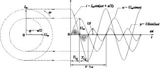
The total resistance of a circuit with a series connection of active and reactive resistance.
In any section of the circuit shown in Figure 2a, the instantaneous current values must be the same, since otherwise accumulations and rarefaction of electrons would be observed at some points in the circuit. In other words, the phases of the current along the entire length of the circuit must be the same. In addition, we know that the voltage phase across the inductive reactance leads the current phase by 90°, and the voltage phase across the active resistance coincides with the current phase (Figure 2b). It follows that the radius vector of voltage UL (voltage across inductive reactance) and voltage UR (voltage across active resistance) are shifted relative to each other by an angle of 90°.
Figure 2. Impedance of a circuit with active resistance and inductance. a) – circuit diagram; b) – phase shift of current and voltage; c) – stress triangle; e) – resistance triangle.
To obtain the radius vector of the resulting voltage at terminals A and B (Fig. 2,a), we will perform a geometric addition of the radius vectors UL and UR. This addition is performed in Fig. 2,c, from which it is clear that the resulting vector UAB is the hypotenuse of a right triangle.
From geometry it is known that the square of the hypotenuse is equal to the sum of the squares of the legs.
According to Ohm's law, voltage must equal current times resistance.
Since the current strength at all points of the circuit is the same, the square of the total resistance of the circuit (Z2) will also be equal to the sum of the squares of the active and inductive resistance, i.e.
(1)
Taking the square root of both sides of this equality, we get,
(2)
Thus, the total resistance of the circuit shown in Fig. 2a is equal to the square root of the sum of the squares of the active and inductive resistance
The total resistance can be found not only by calculation, but also by constructing a resistance triangle, similar to the voltage triangle (Figure 2,e), i.e. the total resistance of the circuit to alternating current can be obtained by measuring the hypotenuse, a right triangle, the legs of which are active and reactance. Of course, measurements of the legs and hypotenuse must be made on the same scale. So, for example, if we agreed that 1 cm of the length of the legs corresponds to 1 ohm, then the number of ohms of total resistance will be equal to the number of centimeters that fit on the hypotenuse.
The total resistance of the circuit shown in Fig. 2a is neither purely active nor purely reactive; it contains both of these types of resistance. Therefore, the phase angle of current and voltage in this circuit will differ from both 0° and 90°, that is, it will be greater than 0°, but less than 90°. Which of these two values it is closer to will depend on which of these resistances is dominant in the circuit. If the inductive reactance is greater than the active one, then the phase angle will be closer to 90°, and vice versa, if the active resistance is predominant, then the phase angle will be closer to 0°.
In the circuit shown in Fig. 3a, active and capacitive resistances are connected in series. The total resistance of such a circuit can be determined using a resistance triangle in the same way as we determined above the total resistance of an active-inductive circuit.
Figure 3. Circuit impedance with resistive resistance and capacitance. a) – circuit diagram; b) – resistance triangle.
The only difference between both cases is that the resistance triangle for the active-capacitive circuit will be turned in the other direction (Figure 3, b) due to the fact that the current in the capacitive circuit does not lag behind the voltage, but leads it.
For this case:
(3)
In the general case, when a circuit contains all three types of resistance (Fig. 4a), the reactance of this circuit is first determined, and then the total resistance of the circuit.
Figure 4. Impedance of a circuit containing R, L and C. a) – circuit diagram; b) – resistance triangle.
The reactance of this circuit consists of inductive and capacitive reactance. Since these two types of reactance are opposite in nature, the total reactance of the circuit will be equal to their difference, i.e.
(4)
The total reactance of the circuit can be inductive or capacitive, depending on which of these two resistances (XL or XC) predominates.
After we have determined the total reactance of the circuit using formula (4), determining the total resistance will not present any difficulties. The total resistance will be equal to the square root of the sum of the squares of the active and reactive resistance, i.e.
(5)
Or
(6)
The method for constructing a resistance triangle for this case is shown in Fig. 4 b.
The total resistance of a circuit with a parallel connection of active and reactive resistance.
CONTENT
- 1. Introduction
- 2 Complex resistance
- 3 Complex voltage and current 3.1 Validity of complex representation
- 3.2 Ohm's law
- 3.3 Phasors
- 4.1 Resistor
- 6.1 Resistance
- 7.1 Series combination
- 8.1 Example
The total resistance of the circuit when the active and reactive elements are connected in parallel.
In order to calculate the total resistance of a circuit composed of active and inductive resistances connected to each other in parallel (Fig. 5, a), you must first calculate the conductivity of each of the parallel branches, then determine the total conductivity of the entire circuit between points A and B and then calculate the total resistance of the circuit between these points.
Figure 5. Circuit impedance when connecting active and reactive elements in parallel. a) – parallel connection of R and L; b) – parallel connection of R and C.
The conductivity of the active branch, as is known, is equal to 1/R, similarly, the conductivity of the inductive branch is equal to 1/ωL, and the total conductance is equal to 1/Z
Total conductivity is equal to the square root of the sum of the squares of active and reactive conductivity, i.e.
(7)
Reducing the radical expression to a common denominator, we get:
(8)
where:
(9)
Formula (9) is used to calculate the total resistance of the circuit shown in Fig. 5a.
Finding the total resistance for this case can also be done geometrically. To do this, you need to construct a resistance triangle on the appropriate scale, and then divide the product of the lengths of the legs by the length of the hypotenuse. The result obtained will correspond to the total resistance.
Similar to the case discussed above, the total resistance when connecting R and C in parallel will be equal to:
(10)
The total resistance can also be found in this case by constructing a resistance triangle.
In radio engineering, the most common case is the parallel connection of inductance and capacitance, for example, an oscillatory circuit for tuning receivers and transmitters. Since the inductor always has, in addition to inductive resistance, also active resistance, the equivalent (equivalent) circuit of the oscillatory circuit will contain active resistance in the inductive branch (Fig. 7).
Figure 6. Equivalent circuit of an oscillating circuit.
It will be interesting➡ What is a phase in electricity?
The impedance formula for this case will be:
(11)
Since usually the active resistance of the coil (R) is very small compared to its inductive resistance (ωL), we have the right to rewrite formula (11) in the following form:
(12)
In an oscillating circuit, the values of L and C are usually selected so that the inductive reactance is equal to the capacitive reactance, i.e., so that the condition is met
(13)
If this condition is met, the total resistance of the oscillatory circuit will be equal to:
(14)
where L is the inductance of the coil in H;
C is the capacitance of the capacitor in F;
R is the active resistance of the coil in Ohms.
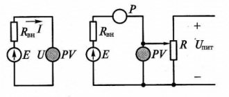
Ohm's law for a complete circuit.
Consider an electrical circuit consisting of a current source and a resistor R.
Ohm's law for a complete circuit establishes the relationship between the current in the circuit, the emf and the total resistance of the circuit, consisting of the external resistance R and the internal resistance of the current source r.
The work of external forces Ast of the current source, according to the definition of EMF (ɛ), is equal to Ast = ɛq, where q is the charge moved by the EMF. According to the definition of current, q = It, where t is the time during which the charge was transferred. From here we have:
Ast =ɛIt.
The heat released when doing work in a circuit, according to the Joule-Lenz law, is equal to:
Q = I2Rt + I2rt.
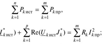
According to the law of conservation of energy, A = Q. Equating (Ast =ɛIt) and (Q = I2Rt + I2rt), we obtain:
ɛ = IR + Ir.
Ohm's law for a closed circuit is usually written as:
.
The current strength in a complete circuit is equal to the ratio of the circuit's emf to its total resistance.
If a circuit contains several series-connected sources with emf ɛ1, ɛ2, ɛ3, etc., then the total emf of the circuit is equal to the algebraic sum of the emf of the individual sources. The sign of the source emf is determined in relation to the direction of the circuit bypass, which is chosen arbitrarily, for example, in the figure below - counterclockwise.
In this case, external forces inside the source perform positive work. Conversely, the following equation holds true for the circuit:
ɛ = ɛ1 + ɛ2 + ɛ3 = | ɛ1| – | ɛ2| -| ɛ3| .
In accordance with the current strength is positive with a positive EMF - the direction of the current in the external circuit coincides with the direction of bypassing the circuit. The impedance of a circuit with multiple sources is equal to the sum of the external and internal resistances of all sources of EMF, for example, for the figure above:
Rn = R + r1 + r2 + r3.
Variable impedance
See also: Network analysis (electrical circuits) § Time-varying components
In general, neither impedance nor admittance can change with time, since they are defined for complex exponentials in which -∞ < m
< +∞. If the complex exponential relationship of voltage to current varies with time or amplitude, the circuit element cannot be described using the frequency domain. However, many components and systems (such as varicaps as used in radio tuners) can have a nonlinear or time-varying voltage-to-current relationship that appears to be linear time invariant (LTI) for small signals and for small viewing windows, so they can be roughly described as if they had a time-varying impedance. This description is approximate: for large signal variations or wide observation windows, the voltage-to-current ratio will not be LTI and cannot be described by impedance.
How to measure electrical impedance
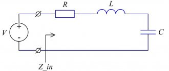
Let's connect all the parts together into a simple electrical circuit. Let's take a look at the figure below: This is a circuit with a DC power supply. Current flows through a resistor. Quite simple, right? The greater the resistance of the resistor in the circuit, the less current will be.
Simple DC circuit with resistor
at 100 ohms to limit current What happens if we add an AC power supply, an inductor, and a capacitor to an electrical circuit? Now there are two additional components in the circuit, each of which offers resistance to electrical current in its own way. Like a resistor, they both prevent the passage of electrical current while also influencing the current. If you add up the active resistance of the resistor and the active and reactance of the capacitor and inductor, you get the total electrical resistance or impedance.
In an AC circuit, a resistor, an inductor and a capacitor are connected in series
Wait! To calculate the total electrical resistance, it is not enough to simply add the active and reactive resistances. Usually, in most textbooks, an abundance of mathematical formulas begins from this point, so read on slowly.
What is it for and where is it used?
Such elements have many uses, but most often they are used as:
- Inductive elements in low-current electrical circuits;
- Reactors in power electronics, as elements for compensating the reactive nature of the load;
- Chokes for smoothing ripples of rectified or alternating current;
- Electromagnets as sources of magnetic field in electromagnetic relays or controls of various devices;
- Inductors in induction heating installations;
- Energy storage in voltage conversion sources;
- Magnetic field sensors (magnetic heads in hard disk drives);
- Signal delay lines;
- Antennas for receiving and transmitting electromagnetic waves.
Inductive antenna
Practical application of electrical impedance
It becomes clear, in the end, that after all our explanations, figuring out what total electrical resistance is is not difficult, isn’t it? There are dozens of free calculators to help you do the calculations. What you really need is to know that impedance works in the same way as resistive resistance to limit the current in an AC circuit.
The ability of components such as capacitors and inductors to respond to constant changes in alternating current makes them unique. Thanks to the impedance in your circuit, you can organize something similar to an electrical panel with circuit breakers that respond to unexpected surges in electricity, protecting your home electrical wiring from burning out. You can also thank impedance for allowing you to carry your laptop with a fully charged battery without fear of it exploding.
When it comes to working with AC powered devices, be it a laptop or the electrical panel in your home, you have electrical impedance to thank. And remember, electrical impedance is simply the big brother of the familiar active resistance, which combines active and reactance into one simple formula.
Complex impedance
Graphical representation of the complex impedance plane
The impedance of a two-terminal circuit element is represented as a complex quantity Z { displaystyle Z} . The polar form conveniently captures both amplitude and phase characteristics as
Z = | Z | e j argument ( Z ) { Displaystyle Z = | Z | e^{j arg(Z)}}
where is the value | Z | {displaystyle | Z |} is the ratio of the amplitude of the voltage difference to the amplitude of the current, and the argument argument ( Z ) { Displaystyle arg ( Z ) } (usually denoted by the symbol θ { displaystyle theta } ) gives the phase difference between voltage and current. j { displaystyle j} is the imaginary unit, and is used instead of i { displaystyle i} in this context to avoid confusion with the symbol for electric current.
In Cartesian form, impedance is defined as
Z = R + j X { Displaystyle Z = R + jX }
where the real part of the impedance is the resistance R {displaystyle R} and the imaginary part is the reactance X {displaystyle X}.
Where it is necessary to add or subtract impedances, the Cartesian form is more convenient; but when quantities are multiplied or divided, the calculation becomes easier if the polar form is used. A circuit calculation, such as determining the total impedance of two parallel impedances, may require conversion between forms several times during the calculation. Conversion between forms follows the usual rules for converting complex numbers.
Calculation of the inductive reactance of the coil
Any inductance, incl. coil provides some resistance to alternating current. How to calculate it was described above. From the formula XL=2pfL it is clear that the resistance of the inductor primarily depends on the frequency of the current flowing through it and its inductance. Moreover, the relationship with both parameters is directly proportional.
Frequency is a characteristic of the external environment; the inductance of the coil depends on a number of its geometric properties:
Where:
- u0 – magnetic permeability of vacuum – 4p*10-7 H/m;
- ur – relative permeability of the core;
- N – number of throttle turns;
- S – its cross section in m2;
- l is the length of the coil in meters.
Having the above-described formulas and information about the material and dimensions of the coil, you can fairly accurately estimate its inductive reactance without any measuring instruments.
Additional Information. Some digital multimeters have an inductance mode. This feature is rare, but sometimes it turns out to be very useful. Therefore, when choosing a device, you should pay attention to whether it is capable of measuring inductance.