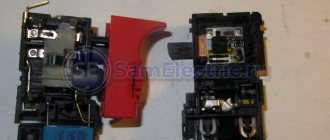
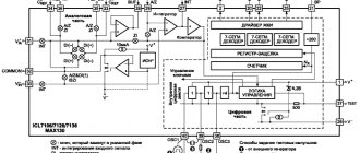
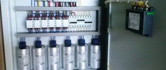
Switches and Dimmers
The simplest temperature control is used in soldering irons with a switch that allows only two positions, and, accordingly, two temperature values.
At the minimum value, the soldering iron mounted on the stand simply maintains the tip in a heated state, and when you press a key or button, the tip heats up to the maximum temperature at which soldering is performed.
Obviously, of the advantages described above, such a soldering iron only has the ability to save energy. The main task of adjustment - the production of high-quality and safe installation of components - remains impossible.
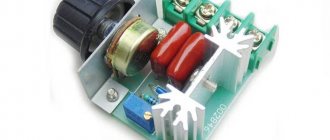
The second type of adjustable soldering irons is dimmable. Their design involves inserting a dimmer into the break in the power cable - a device that limits the power consumption of the soldering iron.
In this case, it really becomes possible to adjust the temperature of the tip, but this is done due to a voltage drop in the dimmer.
Accordingly, there can be no talk of any cost-effectiveness of such a scheme. But the price of such devices is quite low and can play a decisive role in the choice.
The use of control chips in the handle of the device
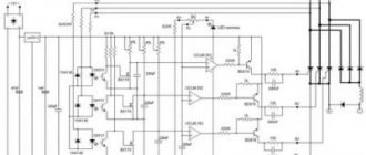
Soldering irons with a temperature control knob located on the handle are popular. Such devices operate on complex microcircuits. Not everyone will be able to make such a design on their own. The main difficulty is the correct firmware of the microcontroller, which is the main component of such a device. To install such a circuit, a radio amateur will need to have a programmer on hand, and experience in writing programs is also desirable.
Copper fixtures
The structure is made of copper wire twisted in a spiral pattern. Copper is capable of transmitting low current produced by small transformers. Adjustable heating components are equipped with a temperature sensor, which is responsible for controlling the tip. The thermocouple is installed on the working tip, which allows you to adjust the temperature level to the required state. The copper spiral does not pass electric current through itself, the performance of the unit stops, or the load indicator changes. Types of copper heaters:
- with wire wound around the body, preventing voltage from reaching the tip;
- The insulated structure avoids heat loss when using the device.
Homemade thermostat
The quality of copper depends on performance; adding additives in order to save money by the manufacturer can significantly reduce the service life and damage the parts being repaired.
Types of regulators
Devices for connecting various types of radio components have several types of characteristics. Soldering stations with heat and load adjustments are produced by the manufacturer with different parameter settings. Main varieties:
- Changing the voltage and power of the node is possible using a triac. This modification is most common when using heating components in radio engineering.
- Thyristor type adjusting element.
- Modification to increase the performance of the device allows you to change the output force to the required values.
- The indication makes it possible to recognize in which mode the heating is being carried out.
- Low-voltage controllers are used in designs designed to operate with a voltage of no more than 36 Volts.
https://youtube.com/watch?v=et60fwS8w5E
You can probably make components that have adjustable temperature volumes with your own hands. A simple structure without interference is used, which makes it possible to extend the service life of the heating element. The galvanic component is considered reliable; its versatility allows the design to be used with various modifications and models.
Types of soldering irons with temperature control
All modern devices, used as individual power tools and as part of soldering stations, depending on the type of heating element and method of heating the tip, are divided into pulsed, devices with nichrome and ceramic heaters.
Pulse soldering iron
Pulse soldering gun
This soldering iron is a device that operates on mains power, reducing the mains voltage but increasing the frequency of the current. This device does not work all the time, only when you press a button on the handle. Thanks to this, it is more economical than analogues of other types, and allows soldering of very small and delicate radio components.
With nichrome heater
The classic nichrome heating element of such a device is a metal tube with fiberglass, mica and numerous turns of thin nichrome wire wound around it. When heated, the wire, which has high resistance, heats up the tube with the copper tip inserted into it.
With ceramic heater
Soldering iron with ceramic heater
In such devices, the tip is placed on a tubular ceramic heating element, which has electrical conductivity and high resistance. When current passes, this ceramic tube heats up almost instantly, providing the fastest possible heating of the tip installed on it.
Power regulator for soldering iron 20-36 VAC
If the soldering iron operates from a network with reduced voltage, you will have to make a separate regulator for it.
Element base
To make such a device yourself, you will need to prepare the following components in advance:
- Transistor KT815B. If this is not the case, you can install KT815G instead.
- Diode bridge KTs401A. KTs402 B or S is also suitable for the regulator.
- Diodes. For the power regulator it is better to use models from the D9 series.
You will also need capacitors. It is recommended to install oxide elements of type K50-6.
Installation features
To make such a regulator, you will have to order a printed circuit board layout in advance and place the entire element base on it. Particular attention must be paid to resistors. The fact is that their parameters are selected depending on the desired control limit.
It is recommended to place all components on an L-shaped radiator. It is necessary to install a socket on the front side or in the upper part of the regulator body to connect a soldering station.
DIY soldering iron power regulator: proven working circuits (6 pcs)
Not everyone likes to buy unknown things. And some people find it more pleasant to make a soldering iron power regulator with their own hands, because this is also experience. Most circuits are assembled using triacs and thyristors; now they are easier to find than transistors. They are also easier to work with, since they are either open or closed, which allows you to make circuits simpler.
Choose any case
Simple thyristor circuits
When choosing a power regulator circuit for a soldering iron, two things are important: power and parts availability. The soldering iron power regulator presented below is assembled using widely used parts that are not a problem to find. The maximum current is 10 A, which is more than enough to perform any kind of work and for soldering irons with a power of up to 100 W. The thyristor in this circuit is used KU202n
Pay attention to the bridge connection. There are many circuits with connection errors
This option is working. Tested more than once.
Temperature controller circuit for a soldering iron using a thyristor
When assembling the circuit, be sure to place the thyristor on the radiator; the larger it is, the better. The circuit is simple, but when it is turned on, it creates interference. You can’t listen to the radio nearby, and to remove interference, we connect a 200 pF capacitor in parallel with the load, and a choke in series. The choke parameters are selected depending on the regulated load, but since soldering irons are usually no more than 80-100 W, the choke can be made at 100 W. To do this, you will need a ferrite ring with an outer diameter of 20 mm, on which about 100 turns are wound with a wire with a cross-section of 0.4 mm².
Another drawback of the diagram translated above is that the soldering iron “itches” noticeably. Sometimes you can put up with this, sometimes you can’t. To eliminate this phenomenon, you can select the parameters of capacitor C1 so that when the variable resistor is set to maximum, the connected lamp barely glows.
On other elements but also without interference
The above regulator can be used for any load. Let's give another analogue, but using a different element base. You can regulate not only the power/temperature of the soldering iron, but also any other load with a small inductive component.
A modified circuit for regulating the power of a soldering iron and any other load with the ripple effect eliminated
There is pulsation here, but its frequency is high and it will not be perceived by our vision. So it can be used not only as a dimmer for a soldering iron, but also to regulate the light from a regular incandescent lamp. Is a diode bridge needed to regulate the heating power of a soldering iron? It won't hurt, but it's not necessary.
On a thyristor with high sensitivity
This circuit allows you to smoothly change the temperature of the soldering iron from 50% to 100%. There are two indicators - power and power. The power presence LED always lights up when turned on, but at 75% power the glow is brighter. The power indicator changes the intensity of the glow depending on the operating mode.
Popular articles Making a cooler for a hard drive.
Power regulator for soldering iron without interference
In order for the regulator to fit into the case of a mobile phone charger, resistances are used of SMD type (1206). All resistors are installed on the board, except for R 10. Some can be composite (we assemble the required value from series-connected resistors).
For normal operation of the circuit, a sensitive thyristor (with a low control current) and a low state holding current (about 1 mA) is required. For example, KT503 (designed for voltage 400 V, control current 1 mA). The rest of the element base is indicated in the diagram.
If assembled, but the voltage is not adjustable
If the assembled regulator does not regulate anything - the temperature of the soldering iron does not change - the problem is in the thyristor. The scheme seems to be working, but nothing happens. The reason is a thyristor with low sensitivity. The currents flowing in the circuit are not sufficient to open. In this case, it is worth installing an analogue with higher sensitivity (lower control currents).
One of the housing options in which you can hide a homemade power regulator for a soldering iron
The regulator may still work, but the soldering iron begins to “itch.” This problem is solved by installing a choke at the output (in front of the soldering iron). The capacity must be selected - it depends on the soldering iron. The second solution is an analog control circuit, and this is a different circuit.
Well, if you have problems with operation, look for either faulty parts or incorrectly selected components. This is usually the problem.
DIY power regulator 1kW
A 1 kW power regulator, assembled with your own hands, can find wide application both on the farm and in the workshop. It is capable of regulating the load current in an AC voltage network. For example, a power regulator can be used to regulate the temperature of a soldering iron tip or heating element. With it you can control the temperature of a 1kW cooking plate. In addition, the power regulator is capable of adjusting the brightness of incandescent lamps or setting the required speed of a commutator motor (grinder, drill, hammer drill).
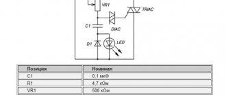
1kW power regulator circuit
The circuit is typical, built on a triac and has the principle of phase regulation. The principle of operation itself is discussed below.
I recommend reading the article “Power regulator for heating elements that does not create interference.”
Circuit components
Resistor R1 with a power of 0.25W, this is quite enough. Variable resistor RV1 with a resistance of 500 kOhm, if used with a lower resistance, then the adjustment will not occur from zero and in a small range.
Capacitor C1 must be designed for a voltage of 400V. There is space on the printed circuit board for a film capacitor.
The LED is ordinary (3V), 3mm in diameter, consuming a current of 20mA. I have a rectangular LED installed with the same parameters.
Triac (triac) BTA08-600B or another. Recommendations for choosing a triac for a power regulator are described below.
The VDS1 LED and the VD1 diode do not need to be installed, but then a jumper must be installed on the printed circuit board instead of one of them.
Principle of operation
The power regulating element of the circuit is a triac or triac VS2. Unlike a thyristor, it can pass load current in both directions, which is very convenient for working in alternating current circuits.
Capacitor C1 is constantly recharged with AC voltage (~220V). Its charge current is limited by resistors R1 and RV1 and also flows through the diode VD1 and the LED VDS1 (alternately). The capacitor is charged and the LED is lit only if a load is connected.
The voltage from the capacitor is supplied to dinistor VS1, which has an opening threshold of 32V. When this threshold is overcome, current begins to flow through the dinistor into the control terminal (G) of triac VS2, which in turn opens.
When the VS2 triac is turned on, the AC load current will flow through terminals A1 and A2 until the load current drops to almost zero (50mA holding current), which will occur when the sine wave passes through zero.
Suppose that the resistance of the rheostat RV1 is 0, then C1 will be freely charged to the opening threshold of the dinistor VS1 in a minimum time. At that moment, while the dinistor, and therefore the triac VS2, is closed, no load current will flow at the output of the power regulator, which means that part of the (minor) sinusoid will be cut off.
Suppose that the resistance of the rheostat RV1 is 250 kOhm, then C1 will charge much longer to the dinistor response threshold, and the triac will remain in the closed position much longer.
With a resistance of RV1 equal to 500 kOhm, the capacitor will practically not be able to charge to the opening voltage of the dinistor, and, therefore, almost the entire sinusoid will be cut off, the triac will be closed almost all the time.
The power regulator will not work without a load, so you should not use it as a voltage regulator.
Triac selection
For this circuit, I do not recommend using triacs of the BT series with a sensitive gate, for example, when installing the BT137-600E, it stopped closing when slightly heated. There were dances with a tambourine. Although I have repeated this circuit with BTA series triacs about a dozen times, assembling regulators for myself and friends, there were no problems with them. An analogue of the BTA series is the BTB series, which is also recommended for this circuit.
With a load of 1 kW, a current of approximately 4.5A will flow through the power regulator triac, so the triac must be designed for a current with a reserve. I recommend using BTA08-600B (current 8A) or BTA10-600B (10A). It is not advisable to set it more powerful, but it is possible. You can install BTA06-600B (6A), but this will reduce the reliability of the power regulator due to too little current reserve.
BTA08-600B pinout.
The BTA series differs from the BTB series in its insulated housing. Both have a metal base, but the triac (BTA) can be mounted on the heatsink without an insulating gasket and bushing, unlike the BTB.
Attention! There are fakes. The photo below shows a BTA16-600B triac, which, according to the technical description, should have an insulated housing, but when checked with a multimeter, the metal base is called to the second terminal (A2), as if it were a BTB16-600B.
Be careful and before installation check the resistance between the base of the triac case and all its terminals with a multimeter, this resistance should be infinite. Otherwise, install the triac on the radiator through insulating sleeves and gaskets, as in the case of the BTB series.
Selection of radiator area
I have done a lot of testing on my 1kW power regulator and can recommend a heatsink with a minimum area of 150cm2. This takes into account that the heat sink is located outside the power regulator housing, and the triac is installed on the radiator using KPT-8 heat-conducting paste.
Below are photographs of an experiment in which a 1kW power regulator was loaded with a water heater, with the current set to 5 Amps. The heat sink (140 cm2) is installed using KPT-8 paste, the housing of the BTA08-600B triac is insulated (the gasket was not installed). Within 15 minutes, the radiator temperature increased to 520C, after which the increase stopped, and for another 45 minutes the temperature remained constant.
The upper limit of the operating temperature of the junction for BTA08-600B is 1250C. The temperature of its case, and especially the radiator, will be significantly lower. Therefore, I strongly recommend choosing the heat sink area in such a way that at a long-term power of 1 kW its temperature does not exceed 60-700C.
Wire cross-section
To connect the board to the network or switching nodes (socket, switch, etc.), a SHVVP wire with a cross-section of 0.75 mm2 is required. You can use VVG wire with a cross-section of 1.5mm2, but it is inconvenient due to its rigidity.
The wire should not be hot during operation.
Do not use thin wires in power regulators; this is unreliable from a fire safety point of view.
Vulnerabilities of the power regulator
The weak points are the screw terminals. They must be of good quality, without backlash. The screws must have intact threads. If the contact is weakened, then this place will heat up and over time the terminals will be destroyed with a possible fire. The terminals can be replaced by soldering.
Printed circuit board
The printed circuit board of the 1kW power regulator has a width of power tracks of 4mm, which is quite enough. After an hour of operation at full power, the tracks are warm (not hot).
Power tracks can be coated with a thick layer of tin, this will increase their cross-section and prevent corrosion.
Power regulator circuit board
Datasheet for BTA08-600B
Soldering iron with adjustable tip temperature: diagrams, types, application – Turner
To perform various electrical work and assemble electronic circuits, a tool such as an electric soldering iron is often used. Its simplest type, which can be purchased at any hardware store, usually has a basic design.
It includes a heating element, a tip, a handle, usually wooden, and a power cable or cord. In some versions, the soldering iron can be equipped with several replaceable tips.
The power of such a soldering iron is fixed, most often 40 or 60 watts. But it is more convenient to use a tool with the ability to adjust power. Such models are also produced, although they are more expensive.
DIY power regulator for a soldering iron - diagrams and installation options
There are many models of soldering irons in stores - from cheap Chinese ones to expensive ones with a built-in temperature controller; they even sell soldering stations.
Another thing is, is the same station needed if such work needs to be done once a year, or even less often? It's easier to buy an inexpensive soldering iron. And some people still have simple but reliable Soviet instruments at home. A soldering iron that is not equipped with additional functionality heats up as long as the plug is plugged in.
And when turned off, it cools down quickly. An overheated soldering iron can ruin the work: it becomes impossible to solder anything firmly, the flux quickly evaporates, the tip oxidizes and the solder rolls off it.
To make work more comfortable, you can assemble a power regulator with your own hands, which will limit the voltage and thereby prevent the soldering iron tip from overheating.
Rating of the best power regulators from Aliexpress
| Photo | Name | Rating | Price | |||
| Complete regulators | ||||||
| #1 | Wenfu GT10000W-SL | ⭐ 5 / 5 | Find out the price | |||
| #2 | YXD Wish 10000W | ⭐ 4.9 / 5 | Find out the price | |||
| #3 | Wenfu ST-BTA41 | ⭐ 4.8 / 5 1 - voice | Find out the price | |||
| #4 | Wenfu GT10000W | ⭐ 4.7 / 5 2 - votes | Find out the price | |||
| #5 | SNDY SNT4000W | ⭐ 4.6 / 5 | Find out the price | |||
| #6 | CHMAWAY 4000W | ⭐ 4.5 / 5 | Find out the price | |||
| Built-in models | ||||||
| #1 | YXD Wish X4CN | ⭐ 5 / 5 2 - votes | Find out the price | |||
| #2 | RQG 4000W | ⭐ 4.9 / 5 1 - voice | Find out the price | |||
| #3 | YXD Wish ACMC100-1 | ⭐ 4.8 / 5 | Find out the price | |||
| #4 | SHENGKU VR-AC220V | ⭐ 4.7 / 5 1 - voice | Find out the price | |||
| #5 | Akin W205 | ⭐ 4.6 / 5 | Find out the price | |||
| Dimmers | ||||||
| #1 | Goodland DC12-24V | ⭐ 5 / 5 | Find out the price | |||
| #2 | Foocle FLS820 | ⭐ 4.9 / 5 1 - voice | Find out the price | |||
| #3 | Vyeofar VF30A-RF | ⭐ 4.8 / 5 | Find out the price | |||
| #4 | HWAYEH DC10-60V | ⭐ 4.7 / 5 1 - voice | Find out the price | |||
| #5 | Luyu LV-2.4G-4054 | ⭐ 4.6 / 5 2 - votes | Find out the price | |||
| #6 | DIY More CZB6721960 | ⭐ 4.5 / 5 | Find out the price | |||
Which power regulator would you choose or recommend?
Take the survey
DIY device design
As follows from examination of the circuit, it consists of a power section, which should be mounted using surface-mounted installation, and a control circuit on a printed circuit board. By the way, they can solder the board at Solderpoint.ru.
Creating a PCB involves making a design of the board. For this purpose, the so-called LUT, which means laser-iron technology, is usually used in everyday conditions. The PCB manufacturing method includes the following steps:
- creating a drawing;
- transferring the design to the board blank;
- etching;
- cleaning;
- drilling holes;
- tinning of conductors.
To create an image of a board, the Sprint Layout program is most often used. After receiving the design using a laser printer, it is transferred to the foil getinax using a heated iron. Then the excess foil is etched using ferric chloride and the pattern is cleaned. Holes are drilled in the right places and the conductors are tinning. The elements of the control circuit are placed on the board and they are soldered (there are certain recommendations on how to solder correctly with a soldering iron).
Assembling the power part of the circuit includes connecting resistors R5, R6 and diode VD2 to the thyristor.
The last stage of assembly is placing the power section and control circuit board in the housing. The order of placement in the housing depends on its type.
Since the dimensions of the power regulator elements on a triac are small and there are few of them, you can use, for example, a plastic socket as a housing. The largest place there is occupied by a variable adjustment resistor and a powerful thyristor. However, as experience shows, all the elements of the circuit, together with the printed circuit board, fit into such a housing.
Temperature controller circuit for a soldering iron
Below is a simple diagram of a power regulator:
I used this circuit for my regulator about 20 years ago, I still use this soldering iron. Of course, some parts, such as transistors, a neon light bulb, can be replaced with modern ones.
Device details:
- Transistors; KT 315G, MP 25 can be replaced with KT 361B
- Thyristor; KU 202N
- Zener diode; D 814B or with the letter B
- Diode;KD 202Zh
- Fixed resistors: MLT-3k, 2k-2 pcs, 30k, 100 ohm, 470k
- Variable resistor; 100k
- Capacitor; 0.1 µF
As you can see, the device diagram is very simple. Even a beginner can repeat it.
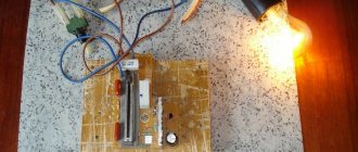
Making a simple soldering iron temperature controller with your own hands
The presented device is built according to the so-called half-wave power regulator. That is, with the thyristor VS 1 fully open, which is controlled by transistors VT 1 and VT 2, one half-wave of the mains voltage passes through the diode VD 1, and the other half-wave through the thyristor. If you turn the slider of the variable resistor R 2 in the opposite direction, then the thyristor VS 1 will close, and the load will have one half-wave that will pass through the diode VD 1:
Therefore, it is impossible to reduce the voltage below 110 volts with this regulator. As practice shows, this is not necessary, since at minimum voltage the temperature of the tip is so low that the tin barely melts.
The part ratings presented in the diagram are selected to work together with high-power soldering irons. If you do not need this, then the power elements, thyristor and diode can be replaced with less powerful ones. If you do not have a two-watt resistor R 5 with a nominal value of 30 kilo ohms, then it can be made up of two series-connected resistors of 15 kilo ohms, like mine:
This device does not require configuration. When assembled correctly and from serviceable parts, it starts working immediately.
Attention! Be careful. This temperature controller does not have galvanic isolation over the network
Secondary circuits have high potential.
All that remains is to choose the appropriate housing size. Place the soldering iron socket:
It is not necessary to take the fuse out; for example, I have it soldered into the break in the power cord. But the variable resistor needs to be installed in a convenient place and, of course, the scale must be calibrated, for example, in volts:
The resulting regulator is very reliable, which has been tested by time, and it will serve you for many years, and the soldering iron will thank you.
User voting
Which power regulator would you choose or recommend?
Wenfu GT10000W-SL
0.00% ( 0 )
YXD Wish 10000W
0.00% ( 0 )
Wenfu ST-BTA41
9.09% ( 1 )
Wenfu GT10000W
18.18% ( 2 )
SNDY SNT4000W
0.00% ( 0 )
CHMAWAY 4000W
0.00% ( 0 )
YXD Wish X4CN
18.18% ( 2 )
RQG 4000W
9.09% ( 1 )
YXD Wish ACMC100-1
0.00% ( 0 )
SHENGKU VR-AC220V
9.09% ( 1 )
Akin W205
0.00% ( 0 )
Goodland DC12-24V
0.00% ( 0 )
Foocle FLS820
9.09% ( 1 )
Vyeofar VF30A-RF
0.00% ( 0 )
HWAYEH DC10-60V
9.09% ( 1 )
Luyu LV-2.4G-4054
18.18% ( 2 )
Classic thyristor regulator circuit
The classic thyristor circuit of the soldering iron power regulator did not meet one of my main requirements, the absence of radiating interference into the power supply network and the airwaves. But for a radio amateur, such interference makes it impossible to fully engage in what he loves. If the circuit is supplemented with a filter, the design will turn out to be bulky. But for many use cases, such a thyristor regulator circuit can be successfully used, for example, to adjust the brightness of incandescent lamps and heating devices with a power of 20-60 W. That's why I decided to present this diagram.
In order to understand how the circuit works, I will dwell in more detail on the principle of operation of the thyristor. A thyristor is a semiconductor device that is either open or closed. to open it, you need to apply a positive voltage of 2-5 V to the control electrode, depending on the type of thyristor, relative to the cathode (indicated by k in the diagram). After the thyristor has opened (the resistance between the anode and cathode becomes 0), it is not possible to close it through the control electrode. The thyristor will be open until the voltage between its anode and cathode (labeled a and k in the diagram) becomes close to zero. It's that simple.
Popular articles Goat from a pompom fur coat
The classical regulator circuit works as follows. AC mains voltage is supplied through the load (incandescent light bulb or soldering iron winding) to a rectifier bridge circuit made using diodes VD1-VD4. The diode bridge converts alternating voltage into direct voltage, varying according to a sinusoidal law (diagram 1). When the middle terminal of resistor R1 is in the extreme left position, its resistance is 0 and when the voltage in the network begins to increase, capacitor C1 begins to charge. When C1 is charged to a voltage of 2-5 V, current will flow through R2 to the control electrode VS1. The thyristor will open, short-circuit the diode bridge and the maximum current will flow through the load (top diagram).
When you turn the knob of the variable resistor R1, its resistance will increase, the charging current of capacitor C1 will decrease and it will take more time for the voltage on it to reach 2-5 V, so the thyristor will not open immediately, but after some time. The greater the value of R1, the longer the charging time of C1 will be, the thyristor will open later and the power received by the load will be proportionally less. Thus, by rotating the variable resistor knob, you control the heating temperature of the soldering iron or the brightness of the incandescent light bulb.
Above is a classic circuit of a thyristor regulator made on a KU202N thyristor. Since controlling this thyristor requires a larger current (according to the passport 100 mA, the real one is about 20 mA), the values of resistors R1 and R2 are reduced, R3 is eliminated, and the size of the electrolytic capacitor is increased. When repeating the circuit, it may be necessary to increase the value of capacitor C1 to 20 μF.
Heating control
To heat a massive part to the required temperature, you need an equally massive soldering iron tip so that the heating rate is higher than the heat removal rate of the part.
A tool that can simultaneously cope with the tasks posed above is a fairly powerful soldering iron with temperature control.
That is, the maximum power of the soldering iron should be sufficient to heat large leads, and the temperature should be regulated within certain limits and selected in accordance with the operating conditions.
Then the massive tip will have greater thermal inertia and will heat the part to the required degree, without the risk of overheating.
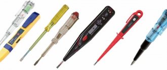
There are several ways to adjust the temperature of the soldering iron:
- maximum-minimum heating (simple switch);
- dimmer adjustment;
- the use of control microcircuits in the handle of the device;
- external control unit;
- using a hair dryer.
https://youtube.com/watch?v=MKZBAqnGoZ4
Using an adjustable soldering iron, in addition to the advantages described above, you can significantly save on electricity consumption for large volumes of work performed, extend the life of the device due to less time operating at maximum power, and reduce the amount of harmful substances released during high-temperature soldering.
DIY temperature regulator
Making a soldering iron with do-it-yourself adjustment requires knowledge of electrical engineering. If you have experience, it is proposed to make the mechanism from a conventional heating element with a power of 60 watts. High-quality connections can only be made when using a heating value balancer. Assembly is carried out by implementing some modifications and involves the use of available materials. The simplest system includes:
- thyristor model KU101G;
- resistor SP – 1;
- diode operating at a current of at least 1A.
Thermostat circuit for a low-voltage soldering iron
Installation of the model is possible without the use of a board, in a power supply housing of any size. The connection is placed on the resistor body, to which the connector for adjusting the degree of heating is adjacent. The result is an adjustable device with an output power of up to 60 watts. A schematic drawing for more powerful devices includes slightly different components. Assembly is carried out on a circuit board; variable resistor R2 is responsible for adjustment, which operates in the range from 50 to 100%. The maximum permissible load is 300 watts, sufficient for a household device. Circuit options depending on the power limiter The power of the device can be adjusted in several ways, the differences lie in the use of a semiconductor controller that performs the necessary tasks. Schemes can be built using several components, depending on the purpose:
- The thyristor works like an electronic switch; the current starts in one direction. The structure is made with three outputs, a cathode, an anode, and a control electrode. Applying a pulse to the electrode causes the thyristor to open; closing occurs after stopping the supply or changing the direction of the current.
- Semiconductors that conduct current in both directions are called triacs. The housing has a control gate and power electrodes; the operation is essentially similar to two connected thyristors.
- The design of control sensors uses parts known to radio amateurs, such as a resistor, diode, capacitor, and microcontroller.
In most cases, a thyristor or triac is used, the precise debugging is regulated using a microcontroller added to the circuit.
DIY soldering iron regulator
This topic has long been mastered by radio amateurs, who are more interested in a high-quality soldering tool than anyone else. We offer you several popular solutions with electrical diagrams and assembly procedures.
Two-stage power regulator
This circuit works on devices powered by an alternating voltage network of 220 volts. A diode and a switch are connected in parallel to each other into the open circuit of one of the supply conductors. When the switch contacts are closed, the soldering iron is powered in standard mode.
When opened, current flows through the diode. If you are familiar with the principle of alternating current flow, the operation of the device will be clear. The diode, passing current in only one direction, cuts off every second half-cycle, reducing the voltage by half. Accordingly, the power of the soldering iron is reduced by half.
Basically, this power mode is used during long pauses during work. The soldering iron is in standby mode and the tip is not very cool. To bring the temperature to 100%, turn on the toggle switch - and after a few seconds you can continue soldering. When the heating decreases, the copper tip oxidizes less, extending the service life of the device.
Dual-mode circuit using a low-power thyristor
This voltage regulator for a soldering iron is suitable for low-power devices, no more than 40 W. For power control, thyristor KU101E is used (VS2 in the diagram). Despite its compact size and lack of forced cooling, it practically does not heat up in any mode.
The thyristor is controlled by a circuit consisting of a variable resistor R4 (a regular SP-04 with a resistance of up to 47K is used) and a capacitor C2 (electrolyte 22MF).
The operating principle is as follows:
- Standby mode. Resistor R4 is not set to the maximum resistance, thyristor VS2 is closed. The soldering iron is powered through a VD4 diode (KD209), reducing the voltage to 110 volts;
- Adjustable operating mode. In the middle position of resistor R4, thyristor VS2 begins to open, partially passing current through itself. The transition to operating mode is controlled using the VD6 indicator, which lights up when the voltage at the regulator output is 150 volts.
Then you can gradually increase the power, increasing the voltage to 220 volts. We make the printed circuit board according to the size of the regulator body. In the proposed version, a housing from a mobile phone charger is used.
The layout is very simple, can be placed in a smaller case. No ventilation is required, the radio components practically do not heat up.
We assemble the device in the housing and take the resistor handle out.
A classic Soviet 40-watt soldering iron easily turns into a soldering station that works more stable than all Chinese analogues.
Triac power regulator
This option also applies to simple circuits designed for low-power devices. Actually, an adjustable soldering iron is usually needed to work with microcircuits or SMD components. And in this case, more power will be unnecessary.
The circuit design allows you to smoothly regulate the voltage from almost zero to the maximum value. We are talking about 220 volts. The power control element is thyristor VS1 (KU208G). Element HL-1 (MH13) gives the control graph a linear shape and acts as an indicator. Set of resistors: R1 - 220k, R2 - 1k, R3 - 300Ohm. Capacitor C1 – 0.1 microns.
Circuit based on a powerful thyristor
If you need to connect a powerful soldering iron to the regulator, the power block diagram is assembled using a KU202N thyristor. With a load of up to 100W, it does not require cooling, so there is no need to complicate the design with a radiator.
The circuit is assembled on an accessible element base; the parts may simply be in your storage rooms.
Operating principle: The soldering iron supply voltage is removed from the anode of thyristor VS1. Actually, this is an adjustable parameter that controls the temperature. The thyristor control circuit is implemented using transistors VT1 and VT2. The control module is powered by zener diode VD1 together with limiting resistor R5.
The output voltage of the control unit is regulated using a variable resistor R2, which actually sets the power parameters of the connected soldering iron. In the closed state, thyristor VS1 does not pass current, and the soldering iron does not heat up. As the control resistor R2 rotates, the power supply produces an increasing control voltage, opening the thyristor.
Principle of operation
Parameters are adjusted using a special mechanism. A soldering iron with a thermostat consists of a tip, a housing, a board and a set of resistors in the structure. The design allows for heat adjustment when working with various parts. More expensive samples offer variable voltage limits
For each setting, you need to select the appropriate tip to control the output temperature. It is important for a novice radio amateur to determine what parameters a soldering iron is required with. Professionals in their field choose reliable models with temperature control
The equipment has good soldering performance, the action is carried out by meeting the necessary criteria. A different load is applied to each product; thermal stabilization allows you to select the boundaries necessary for high-quality soldering of various products.
Network soldering iron with temperature control
The temperature is selected in accordance with the description of the material and method of operation of the equipment used.
Selecting a suitable soldering iron power regulator circuit
A large number of different circuits are used to regulate power. Examples include:
- with variable resistor;
- with resistor and diode;
- with a microcircuit and a field-effect transistor;
- with a thyristor.
The simplest power regulator for a soldering iron is a circuit with a variable resistor. In this option, a variable resistor is connected in series with the soldering iron. The disadvantage of this scheme is that a lot of power is dissipated by the element, which goes into heat. In addition, a high-power variable resistor is a rather scarce element.
A more complex method is using a resistor and a rectifying diode. In this scheme there are three operating modes. In maximum mode, the soldering iron is connected directly to the network. In operating mode, a resistor is connected in series with the tool, which determines the optimal operating mode. When turned on in standby mode, the soldering iron is powered through a diode, which cuts off one half-cycle of the AC mains current. As a result, the power of the soldering iron is reduced by half.
When using a microcircuit and a field-effect transistor, the power of the soldering iron can be adjusted not only downward, but also upward. In this case, the circuit uses a rectifier bridge, the output voltage of which can reach 300 V. In series with a soldering iron for microcircuits, a powerful field-effect transistor of the KP707V2 type is included in the package.
The power of the soldering iron is controlled using the pulse width method. To do this, pulses with an average frequency of 30 kHz are applied to the transistor gate, generated using a multivibrator assembled on a K561LA7 type microcircuit. By changing the generation frequency, you can adjust the voltage on the soldering iron from ten to 300 V. As a result, the current of the tool and its heating temperature change.
The most common option used to regulate the power of a soldering iron is a circuit using a thyristor. It consists of a small number of non-deficient elements, which makes it possible to design such a regulator in very small dimensions. Next, we will consider the circuit of a triac power regulator for a soldering iron in more detail.
Add a link to a discussion of the article on the forum
RadioKot >Competitions >Congratulate Kot as a human being 2022! >
| Article tags: | Add a tag |
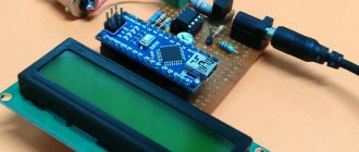
Soldering iron power regulator with digital display from a watch designer for $1.5.
Author: Simurg Published 09.23.2021 Created using KotoEd.
Taking into account modern prices for AVR, STM, it is not rational to assemble simple devices for them. It is easier to make a regulator based on a Chinese watch designer. They contain a very good and bright indicator, which costs more than half the cost of the set if purchased separately. But here the bonus will be the board, the controller and the looseness! The board is almost suitable, you just need to make one jumper to free the INT0 pin from the indicator and reassign it to the pin of a button that we won’t need.
Regulation is carried out with one button. When the power decreases, a minus sign is displayed and the power value as a percentage decreases. As power increases, the minus sign goes out and the power value increases.
In the initial warm-up mode, the countdown timer runs at full power. The timer can be interrupted at any time by pressing the button. After the time has elapsed, the current power as a percentage will be displayed.
If there is no signal from the zero detector, or the input is used for overload protection when the protection is triggered, then the operation of the regulator and timer (if the time has not yet expired) is suspended and a message about this is displayed on the indicator in the form of dashes. Once the signal is restored, the soft start will be started again.
Adjustment with modulation of the control signal for a triac. This is necessary so that if the triac suddenly closes unplanned (especially when working on an inductive load), it is immediately opened again by the next modulation pulse. Also, thanks to modulation, you can use a pulse transformer to control the triac instead of the MOC3023. The program measures the duration of the half-cycle using a timer and uses it to calculate the opening angle in accordance with the specified percentage value.
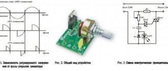
The arrows indicate on the yellow diagram the moment of transition through 0, and on the blue diagram the moment of opening of the triac and modulation. When the value is 100%, the modulation pulses follow continuously.
If the 0 signal disappears in the next half-cycle, the operation will be stopped.
The proteus model is attached in the files. We take the cheapest constructor and use it for remodeling:
View from the paths.
After reworking the board, which consists of trimming one track and soldering one jumper, we get a power regulator that has the following functions:
- — smooth start when turned on from 0 to 100% power;
- — heating timer at full power 3 minutes;
- — stop the timer at any time by pressing a button. Switch to displaying current power in %.
- — after 3 minutes, automatic transition to 50% power;
- - regulation with one button + and - with an accuracy of 1%;
- — protection if the signal from the “0” detector disappears during half of the next period. Screen display “—-”;
- -you can use the “0” detector input in the additional overcurrent protection function;
- — smooth return to the set power after restoration of the signal from the “0” detector;
- As a bonus, we will learn how to flash and write your programs for this controller and this clock designer in 1 day.
Let's add to the former clock any zero detector circuit on an optocoupler and a MOC3023 to control a triac and we get a power regulator.
The clock layout was originally like this:
We need to bring it to the form:
On the board it is necessary to release the INT0 P3.2 pin by transferring the indicator digit to the pin of the P3.4 button that we do not need and unsolder (or not solder) the resistor R3 and the S1 button. Connect the jumper to the battery diode that we no longer need. Also solder the resistors indicated by the arrows to improve performance.
For those who want to write their own program to suit their needs, a small step-by-step hint will help: You need to install the KEIL MVisionV5.11.2.0 program
Next, following the steps in the screenshots, perform a simple project setup: After installation, click the “Project” tab and select a new project
Come up with a name for your project:
Select the controller that is used in the AT89C2051 watch and click OK.
When asked to include a startup in the project, refuse by clicking NO.
An editor window will open. In it, right-click the Source Group 1 folder and select create a new file
Write the file name main and select the language C
Next, in the PROJECT tab, select project settings
In the TARGET tab, specify the frequency of the quartz used in the clock designer set 12.0 MHz. And according to the screenshot, set up optimization
In the OUTPUT tab, specify to create a HEX file, and disable the rest and click ok
Then right-click the Source Group 1 folder and select add new file. Here we will add a library file for working with a seven-segment indicator. Copy it in advance to your project folder
Find the folder and specify the indicator.c file and click add
Here you can write your own code, or copy the source code of the controller from any notepad.
Select the main.c file on the left and paste the code in the window that opens on the right.
Next we need to specify the paths to the folder with the .h files. To do this, right-click on Target 1 and in the PROJECT tab at the top select project settings as we did earlier. There, open the C51 tab and select the add patch button.
Here click on the dashed square CREATE
Click find folder
And specify the path to the folder with headers
Congratulations!!! Now you can compile the project. After compilation, if there are no errors, a firmware file will be created with the extension “your project name.HEX”. It will be located along the path indicated at the top in the blue line.
Now we need to upload the firmware to the controller using the Mini-Pro TL866A or TL866CS programmer or any other programmer and the MiniPro program. In the program, select the type of controller that we will program. Select AT89C2051.
Click open file. Select the .HEX file type and find your firmware file and click OPEN.
Make sure INTEL HEX is selected and click OK.
Insert the controller into the socket according to the picture in the program window and press the PROGRAM button.
Uncheck LOCK BIT and press PROGRAM
Insert the controller into the socket of our former clock, which has become a power regulator and make sure that everything works as intended.
Project files: firmware and proteus model.
Files:
vse
All questions in the Forum.
| What do you think of this article? | Did this device work for you? | |
| 31 | 9 | 11 |
Converters based on controlled diodes
Each of the possible versions of the devices differs in its circuit and control element. There are circuits of power regulators using thyristors, triacs and other options.
Thyristor devices
In terms of their circuit design, most known control units are manufactured using a thyristor circuit controlled by a voltage specially generated for these purposes.
Popular articles Cactus
A two-mode regulator circuit based on a low-power thyristor is shown in the photo.
Using such a device, it is possible to control soldering irons whose power does not exceed 40 watts. Despite its small dimensions and the absence of a ventilation module, the converter practically does not heat up under any permissible operating mode.
Such a device can operate in two modes, one of which corresponds to the standby state. In this situation, the handle of the variable resistor R4 is set to the extreme right position according to the diagram, and the thyristor VS2 is completely closed.
Power is supplied to the soldering iron through a chain with a VD4 diode, on which the voltage is reduced to approximately 110 Volts.
In the second operating mode, the voltage regulator (R4) is moved from the extreme right position; Moreover, in its middle position, thyristor VS2 opens slightly and begins to pass alternating current.
The transition to this state is accompanied by the ignition of the VD6 indicator, which is activated when the output supply voltage is about 150 Volts.
By further rotating the R4 regulator knob, it will be possible to smoothly increase the output power, raising its output level to the maximum value (220 Volts).
Triac converters
Another way to organize the control of a soldering iron involves the use of an electronic circuit built on a triac and also designed for a low-power load.
This circuit works on the principle of reducing the effective voltage value on the semiconductor rectifier, to which the payload (soldering iron) is connected.
The state of the control triac depends on the position of the “switch” of the variable resistor R1, which changes the potential at its control input. When the semiconductor device is completely open, the power supplied to the soldering iron is reduced by approximately half.
The simplest control option
The simplest voltage regulator, which is a “truncated” version of the two circuits discussed above, involves mechanical control of power in the soldering iron.
Such a power regulator is in demand in conditions where long breaks in work are expected and it does not make sense to keep the soldering iron on all the time.
In the open position of the switch, a small amplitude voltage (approximately 110 Volts) is supplied to it, ensuring a low heating temperature of the tip.
To bring the device into working condition, just turn on the S1 toggle switch, after which the soldering iron tip quickly heats up to the required temperature, and you can continue soldering.
Such a thermostat for a soldering iron allows you to reduce the temperature of the tip to a minimum value in the intervals between solderings. This feature slows down oxidative processes in the tip material and significantly extends its service life.
The simplest energy regulator
The first designs of devices that varied the power supplied to a load were based on Ohm's law: electrical power equals current times voltage or resistance times current squared. A device called a rheostat was designed on this principle. It is located both in series and in parallel with the connected load. By changing its resistance, the power is also adjusted.
The current entering the rheostat is divided between it and the load. When connected in series, the current and voltage are controlled, and when connected in parallel, only the value of the potential difference is controlled. Depending on the material from which the resistance is made, rheostats can be:
- metal;
- liquid;
- coal;
- ceramic.
According to the law of conservation of energy, the absorbed electrical energy cannot simply disappear, therefore, in resistors, power is converted into heat, and if its value is large, it must be removed from them. To ensure removal, cooling is used, which is performed by blowing or by immersing the rheostat in oil.
A rheostat is a fairly universal device. Its only, but significant, disadvantage is the generation of heat, which does not allow making a device with small dimensions if it is necessary to pass large amounts of power through it. By controlling current and voltage, a rheostat is often used in low-power lines of household appliances. For example, in audio equipment to adjust the volume. It is not at all difficult to make such a current regulator with your own hands; this applies to a greater extent to a wire rheostat.
How to choose a power regulator? Main criteria
To choose a suitable device, it is worth comparing its characteristics with the purposes and features of the application. There is often no point in buying a more expensive model if some of its functions are simply not needed.
Analog or digital?
Digital power controllers began to appear on the market relatively recently. Therefore, analog models have not yet become obsolete, although they have significant disadvantages compared to more modern ones running on microprocessors.
Table. Differences between an analog power controller and a digital one
| Characteristic | Analog | Digital |
| Principle of operation | Relay or servo driven | Triac or thyristor |
| Performance | Worse | Better |
| Flexibility of control and configuration | Standard system - one or more rotary knobs, levers or buttons | There is an LCD screen, more buttons |
| Output power control | Less precise (for example, placing a lever opposite the desired scale indicator) | More accurate (you can enter the value manually or at least monitor it on the LCD) |
| Current limiting system | Disposable fuses (blow quickly, but need to be replaced) | Electronic limiter (sometimes it operates slower than fuses, especially in budget models, but does not need to be replaced) |
| Automation of control | No | Yes (you can configure it at your discretion for a specific task and do not have to “twist the knobs” every time) |
| Emergency Alert System | Yes, but not often | Yes, but not always |
| Price | Below | Higher |
Important! There are digital regulators that combine an electronic current limiter with fuses. Such devices are considered the safest and most reliable, but their operation is associated with additional costs - you need to buy new fuses after the old ones have tripped.
Home or professional?
All power regulators can be divided into 2 conditional groups - for household and for professional use. The device must be selected depending on the purpose. A radio amateur who turns on a soldering iron at his leisure does not need a professional device - it’s just an extra expense.
Built-in or complete?
To use a built-in regulator, you need an electrical cabinet (or just a metal box of suitable dimensions). Without this “harness” it is inconvenient to work with the device. If you don’t have such a cabinet at home, then it’s better to buy a complete model - it is placed on the floor or hung on the wall, after which you can use the device without lengthy setup.
Built-in power regulator
Power
The power of the device must be selected in accordance with the tasks:
- a maximum power of 10,000 W will be sufficient not only for domestic purposes, but also for industrial use;
- 4,000 W is enough for almost all household appliances;
- less than 2,000 W - such devices are suitable only for lighting control (lamps, lamps, car dashboard, etc.) and for low-power electrical appliances.
Protection system
A good power regulator has protection against:
- short circuits;
- “sticking” and “loss” of phases;
- overload and overheating.
Short circuit protection is a weakness of most cheap devices. Formally, it exists, but it does not work very quickly. Sometimes the device manages to fail before the protection works. Therefore, if the voltage is unstable (when the risk of a short circuit is real), it is worth overpaying and choosing a power regulator with good protection based on an electronic limiter.
Important! Many European-made models operate with improved fuses. They respond quickly and are very reliable. The problem is that a new fuse costs several tens of dollars.