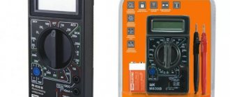
The DT-182 is a typical DT830 digital multimeter, just slightly smaller in size. An unpleasant feature of this multimeter is that it is not protected from damage when voltage is applied to the input in resistance measurement mode. Very often, this causes failure of the ADC IC, made using unpackaged technology. Even if there are contact pads on the board, it is extremely difficult to find a suitable replacement. But with the price of the DT-182 being only $4, it’s easier to throw out the old one (after removing the 12 V battery and probes) and buy a new one.
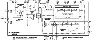
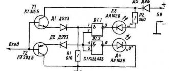
To repair such devices, we provide an approximate diagram and location of radio elements on the board.
The microcircuit can withstand an input voltage of 1.5. 1.8 V. For microcircuits with an unknown pin arrangement, the input can be found by the wiring parts or by the next measurement of the voltage between the common wire of the device - the “COM” probe - and each of the IC terminals. In the “Measurement of diodes-continuity” and “200 Ohm” modes with open probes, this voltage is 1.10 V, in the “2k” - “2M” modes - 130 mV. When the probes of the device being measured are shorted, the input voltage of the IC becomes zero.
To control the supply voltage, it is necessary to lead a wire from the negative pole of the battery to a countersunk bolt on the device body. When connecting your own probe “V; Ohm" of the device at the "20 V" limit, the battery voltage value minus 3 V of the internal stabilizer will appear on the indicator, i.e. when the supply voltage DT182 is 12 V, the readings are -9 V. It is allowed to reduce the supply voltage to -7 V, the device readings to -4 V. The parameters of the measured quantities and their limits are in the photo below.
The wires of the probes that come with the DT-182 are too thin and unreliable, and they are not secured in the probes themselves, so after a small number of turns of the wire in the probes, it comes off. Also, such thin wires give a considerable error when measuring resistance of 10 ohms or less. After purchasing a multimeter, it is recommended to immediately replace the wires with others with a larger cross-section, and fix them in the plastic probes themselves by wrapping PVC insulation removed from a thin wire on top and forcefully inserting the wire back into the probe.
Another weak link is the springy battery contacts. Unlike the usual 9 V crown used in full-size DT-830 multimeters, a 23A mini-finger disk battery (this is not amperes) at 12 V is installed here.
Due to the thin strips of metal contacts, they do not spring well and after several battery replacements they do not touch the battery at all. All that remains is to replace them with more reliable ones or even solder the power wires to the battery. By the way, this particular defect was in this device, which was brought to me for repair.
Overall, it turned out to be a pretty good compact, universal measuring device, with many measurement modes, but not very reliable. If small sizes are your main concern, buy it, but in other cases it’s better to stick with the classic DT-830.
Description of the device
The DT-182 multimeter is a digital instrument with reduced dimensions. It is also a universal tester for basic home measurements. Designed to measure direct and alternating current with voltage, resistance, diodes, and ring diodes with high accuracy. Suitable for professional electricians and ordinary users. Power is supplied by a small-sized twelve-volt 23A battery.
Note! It can be either portable or stationary. It has one purpose - to see what is happening in the electrical circuit, whether there is voltage with resistance in it.
It is worth pointing out that, unlike a dial gauge, a digital gauge has a much more convenient design. In addition, it works faster. Updates occur up to twenty times per second.
Principle of operation
The multimeter works thanks to double integration, an analog-to-digital converter in which the input signal is equal to the reference signal. To indicate the value of an electrical parameter, the meter must be connected to the circuit or its component. These connections are made using a set of wires. The black wire is common and the red wire is positive. One end of the wire contains a plug that plugs into a socket. The other end is used to make contact with the circuit or its measured component. To measure direct current, the device must be connected in series. Since the voltage is the same throughout the circuit, it will be on the meter.
Structure of a multimeter
Before starting work, it is necessary to study the components of the device, because Instructions are not always included; we have prepared their description:
- Dial: Has arc-shaped scales visible through a glass or plastic display. The pointer on the display shows the scale values. If you use a digital multimeter (mastech mas838, ms8230b, m890d, dt700d, dt 9202a, 59002, mas830, my64), then its dial will be replaced by an LED display.
- Pointer or pointer: This is a thin black needle at the leftmost position in the dial window, designed to display measured data on pointer devices - yx 360trn, pmm 600, sunwa yx 1000a, m83. Before using a dial multimeter, be sure to read the instructions, especially the “division values” section.
- Switch or button: Allows you to change the functions (voltmeter, ammeter, ohmmeter) and scale (x1, x10, etc.) of the meter. Many functions have multiple ranges, just like touch switches. It is important to have a full range of operating modes. Most meters use the type of knob shown in the picture, but there are others. Regardless, they work similarly. Some meters have an "Off" position that serves as a switch, while others have a separate button to turn the meter on. The meter should be set to the "Off" position when storing.
- Jacks or holes in the housing to insert probes. Most multimeters have multiple sockets. One is usually labeled COM or (-) for general and negative. To connect the black probe. The other terminal is labeled V (+) and the Omega symbol for Volts and Ohms, respectively, and positive charges. The + and – symbols represent the polarity of the probe when installing and testing the DC current value. If the test leads are installed according to the instructions, the red lead will be positive and the black lead will be negative. Many instruments have additional connectors that are required for high voltage testing.
- Test Leads with Clamps: The tester comes with 2 leads: one black and one red.
- Battery and fuse compartment: usually located on the back side. Fully charged batteries will be required for resistance and continuity of testing.
- Zero Adjustment: This small button is usually located near the dial called Ohm Adjust, 0 ADJ, or similar. Used only in ohmmeter or resistance range measurement mode while the sensors are closed, for example, to set the boiler thermostat.
Video review of working with a multimeter
Device characteristics
According to the characteristics, it is suitable for double integration, has a 3.5-inch digit liquid crystal display, and has automatic polar indication. Measures in a second. It has an operating temperature range of 40 degrees. Operates at 80% humidity. Can be used to measure equipment having 23 A. Has a resolution of 1-10 mV. Measures with minimal error.
Terms of use
When answering the question about how to use dt 182, it is worth pointing out that you need to use the measuring device according to the instructions included with each device. All the user needs to do is select the measurement function, connect the test leads, black to the neutral conductor and red to the phase conductor, and then press the button to measure. As a result, the indicator will be displayed in amperes, watts or kilowatts, depending on the selected mode.
Measured quantities
A multimeter allows you to measure electrical characteristics. Using the multimeter tool is very easy with the manual. There are those options that can show the temperature. Today, thanks to this model, it is possible to measure voltage with current in an electric motor, radio component, switch, light inductive coil, microcircuit, relay, and others. Thanks to the tester, you can measure direct and alternating current, conductor resistance, a section of a circuit or the current force in a section of an electrical circuit that has a switched on load. This multimeter can also calculate capacitance.
Continuity testing of diodes and wiring is the most common mode of application, since the socket with the switch often suddenly stops working, the contact begins to disappear, or the power supply circuit is completely broken. This is why you need an electrical appliance. It helps to find out whether the wires have contact or whether they will need to be repaired.
Note! It is worth pointing out that, in addition to at home, a multimeter is often used in a car to check the serviceability of the generator, starter, and battery.
Refinement of the DTI82 multimeter
The DT182 is a small multimeter measuring 100x50x20mm, very convenient for field measurements. Such multimeters are not protected from damage when voltage is applied to the input in resistance measurement mode.
The only thing left to do is throw away the multimeter. Sometimes it is not so much the device itself that is so expensive as its absence. To repair such devices, it is not necessary to know their diagram; after purchasing the device, it is enough to remove the back cover of the case, draw the location of all the elements on a sheet of paper and put down their values (Fig. 1).
It is advisable to glue a sheet with the location diagram and part ratings to the back cover of the multimeter.
Multimeter dt-182
The DT-182 is a typical digital one, only with slightly reduced dimensions.
But with the price of the DT-182 being only $4, it’s easier to throw out the old one (after removing the 12 V battery and probes) and buy a new one.
To repair such devices, we will also show the location of the radio elements on the board.
The microcircuit can withstand an input voltage of 1.5-1.8 V. For microcircuits with an unknown pin arrangement, the input can be found by the wiring parts or by regularly measuring the voltage between the common wire of the device - the "COM" probe - and each of the IC pins. In the "Measurement" modes
Using a Multimeter to Measure Voltage (Volts)
Set the meter to the highest range provided for AC Volts. It is not yet known what voltage will be the highest, so to avoid damaging the device, we set the indicator to maximum.
- Insert the black probe into the COM or - hole. Volt Figure 1
- Insert the red probe into the V or + hole. Volt Figure 2
- Turn the meter knob to the desired mode (DCV or ACV) (Figure 3). The maximum scale value must coincide with the knob range selector. Voltage readings are linear. Division accuracy up to 0.001 (Figure 4)
- Check the general electrical outlet.
- Insert the black wire into one of the holes in the installed socket, and the red wire into the other. Unplug the wires from the socket and turn the switch knob to the lowest range. Volt Figure 5
- If the pointer did not move, it is likely that DC mode was selected instead of AC. The fact is that this error can be fatal, especially if the measurement is carried out to change the wiring in the apartment, so it is better to check the voltage in both modes.
Figure 3. Selecting the voltage measurement mode in the multimeter
Figure 4. Setting the ACV range in the multimeter
Figure 5. Measuring the voltage in a socket with a multimeter
How to use a multimeter dt 182, 830b, 832, 838, 9205a, 9208a and others
» A multimeter is an instrument used to test DC or AC voltage, resistance or continuity of current in a circuit.
Let's look at 3 ways to use a multimeter for dummies to find out if there is current in the local electrical network. Before starting work, it is necessary to study the components of the device, because
instructions are not always included, we have prepared their description: Dial: Has arc-shaped scales visible through a glass or plastic display. The pointer on the display shows the scale values.
If you use a digital multimeter (mastech mas838, ms8230b, m890d, dt700d, dt 9202a, 59002, mas830, my64), then its dial will be replaced by an LED display.
Structure of a multimeter
Before starting work, it is necessary to study the components of the device, because Instructions are not always included; we have prepared their description:
- Dial: Has arc-shaped scales visible through a glass or plastic display. The pointer on the display shows the scale values. If you use a digital multimeter (mastech mas838, ms8230b, m890d, dt700d, dt 9202a, 59002, mas830, my64), then its dial will be replaced by an LED display.
- Pointer or pointer: This is a thin black needle at the leftmost position in the dial window, designed to display measured data on pointer devices - yx 360trn, pmm 600, sunwa yx 1000a, m83. Before using a dial multimeter, be sure to read the instructions, especially the “division values” section.
- Switch or button: Allows you to change the functions (voltmeter, ammeter, ohmmeter) and scale (x1, x10, etc.) of the meter. Many functions have multiple ranges, just like touch switches. It is important to have a full range of operating modes. Most meters use the type of knob shown in the picture, but there are others. Regardless, they work similarly. Some meters have an "Off" position that serves as a switch, while others have a separate button to turn the meter on. The meter should be set to the "Off" position when storing.
- Jacks or holes in the housing to insert probes. Most multimeters have multiple sockets. One is usually labeled COM or (-) for general and negative. To connect the black probe. The other terminal is labeled V (+) and the Omega symbol for Volts and Ohms, respectively, and positive charges. The + and – symbols represent the polarity of the probe when installing and testing the DC current value. If the test leads are installed according to the instructions, the red lead will be positive and the black lead will be negative. Many instruments have additional connectors that are required for high voltage testing.
- Test Leads with Clamps: The tester comes with 2 leads: one black and one red.
- Battery and fuse compartment: usually located on the back side. Fully charged batteries will be required for resistance and continuity of testing.
- Zero Adjustment: This small button is usually located near the dial called Ohm Adjust, 0 ADJ, or similar. Used only in ohmmeter or resistance range measurement mode while the sensors are closed, for example, to set the boiler thermostat.
Video review of working with a multimeter
Multimeter dt 182 how to use
First of all, we will briefly tell you what is on the front panel of the measuring device and what functions you can use when working with the tester, after which we will tell you how to measure resistance, current and voltage in the network.
- Ω - resistance;
- OFF – tester is turned off;
- DCA – direct current;
- DCV – constant voltage;
- ACV – alternating voltage;
You can clearly see the front appearance of the electronic tester in the photo:
You probably immediately noticed the 3 connectors for connecting probes?
Using a Multimeter to Measure Resistance
Many people do not know how to use a multimeter to measure resistance, but this is its main function, which will be especially useful if you need to install electrical wiring in an apartment or house. Set the multimeter to the Ohm reading by turning the knob to the appropriate reading (Figure 1).
Figure 1. Measuring resistance with a multimeter
Pay attention to the meter readings. If the test leads are not in contact with any object, the pointer needle or analog meter of the tester will deviate to the left; when working with a digital device, the value will “jump” to the larger side. This represents an infinite amount of resistance, or "opening", but also means that there is no communication path between the black and red probes.
- Connect the black probe to the -COM connector (Figure 2)
- Connect the red probe to the socket marked Omega (the symbol representing Ohm) or the letter "R" or "P" next to it (Figure 3)
- Set the range (if available) to R x 100 (Figure 4)
- Keep the test lead probes together. The instrument needle should move completely to the right side of the dial. Find "zero settings" and rotate the knob until the meter reads 0 (or as close to 0 as possible) (Figure 5)
Figure 2. Connect the black probe to -COM
Figure 3. Connecting the red probe to the letter P (+) of the multimeter
Figure 4. Setting the range on the multimeter
Figure 5: Multimeter Zero Adjustment
Note that this position is called "Short" or "Ohms at Zero" and the reading for this range is 1 R X. Ohms Figure 6
Figure 6. Ohms at multimeter zero
Replace batteries (if necessary). If the ohmmeter does not show 0, this may mean that the batteries are low and need to be replaced.
Practice. How to use a multimeter
If you have asked the question “How to use a multimeter?”, then you at least already know what electric current and voltage are.
If not, then I suggest you read the first chapters of my. So what is a multimeter? A multimeter is a universal combined measuring instrument that combines the functions of several measuring instruments, that is, it can measure a whole range of electrical quantities.
The smallest set of functions of a multimeter is measuring voltage, current and resistance.
However, modern manufacturers do not stop there, but add to the set of functions such as measuring the capacitance of capacitors, current frequency, diode continuity (measuring the voltage drop across the pn junction), an audio probe, temperature measurement, measuring some transistor parameters, a built-in low-frequency generator and much more. With such a set of functions
How to use the proconnect dt 182 multimeter
It works on the principle of voltage generation by these conductors due to temperature changes in any part of the sensor.
So, how to check a thermocouple with a tester if the button on the gas boiler box does not lock during operation. To identify such a malfunction, do the following:
- Turn off the boiler completely, cutting off the supply of gas and electricity.
Important How many lamellas should there be for the tester operating mode switch?
Grigory / 10/13/2016 - 22:39 And my DT-182 circuit does not at all coincide with your circuit.
Can you advise me how to modify my DT-182?
https://fastpic.ru/view/82/2016/1013/c6641d3f4ab309abd011f89660d5a76f.jpg.html Vlad / 05/23/2016 - 16:01 And who will tell you how to treat the following: The device is lying in the readings, at position 20V it shows -0.37?
How to use a multimeter correctly
A multimeter is a universal device for checking the integrity and parameters of an electrical circuit. It combines the functions of an ohmmeter, ammeter and voltmeter.
With its help, you can take readings of direct and alternating voltage, find out the current and resistance.
All this data is easy to obtain using any type of device: pointer or digital. However, not all users know how to use a multimeter correctly.
All multimeters or multitesters are divided into two large subgroups: Analog. They are made in the form of a scale and arrow.
When working with such a device, it is necessary to take into account the indicators of the established limit, which a professional electrician is well versed in. Digital. Modern options that show the value on a digital display, with a parameter switch knob or push-button control.
Advanced versions have functions for reading parameters of capacitor capacitance, frequency and pulse duration.
Ammeter mode of a multimeter
How to properly use a dt 832, dt 838, dt 830b, dt9205a multimeter in voltage measurement mode in a car? This is not difficult to learn. Set the meter to the highest AC or DC current reading if the Amp range is supported.
Please note that most multimeters will only measure a very small amount of current in the µA and mA ranges. These are values of current that flow only in the finest electronic circuits, and are thousands (and even millions) of times less than the values in any home electrical network. For example, a typical 100W/120V emergency light bulb requires 0.833 amps.
- Insert the black probe into the COM or -.
- Insert the red probe into -. Turn off the power to the circuit, disconnect the isolation transformer.
- An ammeter is placed in series with the circuit to measure current. Polarity must be observed. Current flows from the positive side to the negative side. Set the current range to the highest value (Figure 1)
- Apply power and adjust the data range to decrease. Do not exceed the range of the flow meter, otherwise it may be damaged. A reading of about 2 mA should be indicated since from Ohm's law I = V / R = (9 volts) / (4700 Ω) = 0.00191 = 1.91 mA amps.
Figure 1. Setting the current range
Some important nuances:
- If the multimeter stops working, check the fuse. In some cases it is necessary to use surface terminals (Figure 2)
- Never connect the instrument through a battery voltage source or if it is installed to measure current (amps).
- It is important not only to know how to use the device, but also to choose high-quality devices. Test the device immediately upon purchase!
- In addition to theoretical knowledge, we offer to gain practical skills and watch a video on how to use a dial and analog digital multimeter of the digital series - dt 830v, dt 181, dt9208a, dt 182.
Figure 2. Multimeter surface terminals
Multimeter dt 182 how to use
DT 182 DC CURRENT RANGE CONTENTS 200 mA SAFETY RULES CHARACTERISTICS PANEL DESCRIPTION DC VOLTAGE MEASUREMENT AC VOLTAGE MEASUREMENT DC CURRENT MEASUREMENT RESISTANCE MEASUREMENT DIODE TEST AND CO Continuity UNITS REPLACE BATTERY REPLACE FUSE This compact digital multimeter is designed to measure DC, AC current and voltage, resistance, diode testing, sound testing with high accuracy and simplicity. Lightweight and small in size with a case and probes hidden in the body, this tool will serve you for many years.
SAFETY INSTRUCTIONS - Always ensure that the function switch is set to the correct position.
— To avoid electrical shock, use CAUTION when measuring high voltages. Always turn off the circuit under test before connecting probes to it. — Before measuring resistance, make sure that all power sources (DC)
How to use a multimeter - instructions for dummies
So, on the front side of the digital multimeter there are the following symbols:
- OFF – tester is turned off;
- DCV – constant voltage;
- Ω - resistance;
- ACV – alternating voltage;
- DCA – direct current;
You can clearly see the front appearance of the electronic tester in the photo: You probably immediately noticed the 3 connectors for connecting probes? So here we need to immediately warn you that it is necessary to correctly connect the tentacles to the tester before taking measurements.
The black wire is always connected to the output labeled COM. Red according to the situation: in order to check the voltage in the network, current up to 200 mA or resistance, you must use the “VΩmA” output; if you need to measure the current value above 200 mA, be sure to insert the red probe into the socket marked “10 ADC”. If you do not take this requirement into account and
Digital multimeter DT-182.
Your vote for the video
- Santiz — Forgotten Bala (2019) (Lyrics)
- WICER WILLOW (FROM A REGULAR BUSH!)
- USA CINEMA 438. American women and infidelity
- Igor Demarin Igor Demarin
- Prozorovo! Monastery! Baba Manya sings the Virgin Mary
top videos » Fassen.net – Video surfing Loading. The latter were discussed by the site goodly pro. Goodly pro reviews. Goodly pro personal account Custom John Deere Tractor Project for sale!
Make offer LEADER AMONG MOPEDS WITHOUT REGISTRATION. STORM CROSS(REVIEW) Where to buy a Metal detector in Israel. My experience and advice. Very simple sandblasting of spark plugs Replacing bearings in roller ski wheels TOP 3 EASY AND BEAUTIFUL HAIRSTYLES FOR SCHOOL IN 5 MINUTES We make a gasket from silicone.
