Visually detectable defects (manufacturing defects)
It is most convenient to check the serviceability of the device at the initial stage of repair by examining its electronic circuit. For this case, the following troubleshooting rules have been developed:
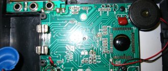
- it is necessary to carefully examine the printed circuit board of the multimeter, which may have clearly visible factory defects and errors;
- Particular attention should be paid to the presence of unwanted short circuits and poor-quality soldering, as well as defects on the pins along the edges of the board (in the area where the display is connected). For repairs you will have to use soldering;
- Factory errors most often manifest themselves in the fact that the multimeter does not show what it should according to the instructions, and therefore its display is examined first.
If the multimeter gives incorrect readings in all modes and the IC1 chip heats up, then you need to inspect the connectors to check the transistors. If the long leads are shorted, then the repair will simply consist of opening them.
In total, there can be a sufficient number of visually detectable faults. You can familiarize yourself with some of them in the table and then eliminate them yourself. (at: https://myfta.ru/articles/remont-multimetrov.) Before repairs, you need to study the multimeter diagrams, which are usually given in the passport.
Why is the mode called “dialing”?
It was possible to check the integrity of the circuit before using the resistance measurement mode - an ohmmeter. The main difference between dialing is that during measurements, if there is an electrical connection between the tested areas, then, in addition to the readings on the screen, a sound signal is heard - a buzzer, which is where the term dialing or ringing came from.
This sound signal significantly speeds up the verification process, you don’t have to be distracted, look at the screen, and it’s not always convenient, and when you hear the buzzer (or not), you already know the result. This is especially useful for mass measurements, for example, when searching for one specific wire in a bundle.
Checking the display
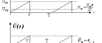
If they want to check the serviceability and repair the multimeter indicator, they usually resort to the help of an additional device that produces a signal of a suitable frequency and amplitude (50-60 Hz and units of volts). If it is not available, you can use a multimeter type M832 with the function of generating rectangular pulses (meander).
To diagnose and repair the multimeter display, you need to remove the working board from the device body and select a position convenient for checking the indicator contacts (screen up).
After this, you should connect the end of one probe to the common terminal of the indicator under study (it is located in the bottom row, far left), and with the other end, alternately touch the signal terminals of the display.
In this case, all its segments should light up one after another according to the wiring of the signal buses, which should be read separately. Normal “activation” of the tested segments in all modes indicates that the display is working properly.
Additional Information. This malfunction most often manifests itself during the operation of a digital multimeter, in which its measuring part fails and requires repair extremely rarely (provided that the requirements of the instructions are met).
The last remark concerns only constant quantities, when measuring which the multimeter is well protected against overloads. Serious difficulties in identifying the causes of device failure most often occur when determining the resistance of a circuit section and in testing mode.
Understanding the multimeter device
To measure current strength, special devices are used, the name of which speaks for itself - ammeters. Ammeters most often found on sale are permanently installed, in the form of panels or for DIN rails. They are usually mounted in a distribution board and allow you to monitor current current indicators, for example, for the entire local power supply system or on some dedicated line.
Ammeters for stationary installation - panel type (left) and for installation in a distribution board on a DIN rail
Such devices are installed, if necessary, only by electrician specialists. Measuring the strength of flowing current using them is as easy as shelling pears. You just need to look at the current readings with the load on the line.
This, in fact, limits their functionality. Naturally, the owner of the apartment (house) will not have the opportunity to remove such a device from its permanent installation site to carry out measurements in another place.
Another option, which already allows you to work in the right place, is the so-called laboratory ammeter. A tabletop device that has terminals, that is, it is possible to connect test leads with probes to check the current strength in a particular section of the circuit.
Laboratory ammeter - limited functionality makes such devices unclaimed for household use.
But purchasing such a “device” for a home instrumental “arsenal” hardly makes sense. Simply for the reason that everything is limited to measuring current strength. And this measurement, by the way, as already mentioned, is carried out at the “everyday” level, perhaps least often.
Therefore, such devices have not gained popularity. And the best option is a multitester (multimeter).
These multifunctional measuring instruments are available for sale in a very wide variety. The first, immediately noticeable difference is that instruments can be pointer-type, with readings taken from scales. Despite the fact that they are considered “yesterday”, some masters prefer them. But for a beginner, it can be difficult to read the readings at first - it’s easy to get confused with scales and steps from the graduation due to inexperience.
“Display” of the once very popular multimeter Ts4353. One arrow and many scales, which can be difficult for a beginner to understand.
Therefore, digital multimeters that display readings in absolute terms on the display are still the most popular. The ability to use such devices is acquired much faster. The cost of many models is very affordable, and such multitesters have become part of the home toolkit.
But even among them there are significant differences that need to be known and taken into account when measuring electrical parameters.
The most convenient are probably multimeters, in which it is enough to set only the measurement mode. The permissible range is not indicated - the device will automatically adjust to the parameters of the circuit, take measurements and give the desired result.
Prices for multimeter Ts4353
multimeter Ts4353
An example is shown in the illustration:
Easy-to-use multitester, which simplifies the installation of operating modes
The mode switch handle (item 1) has only a few positions. This voltage is a combination of alternating V AC (~ symbol) and constant DC (-), in the volt and millivolt range. Similarly with the current strength - A, also without division into the type of current, but with gradation into amperes and milliamps. In addition, there is always an option for measuring resistance and continuity of the circuit. There may be other built-in functions.
At the bottom there are sockets for connecting test leads with probes. There are three or four of them. There must be a COM for “ common” wire (item 2), usually black. Socket pos. 3 – for the red wire when carrying out the vast majority of measurements. Under the socket there is an inscription indicating the permissible measurement limits for voltage and current. And finally, nest pos. 4 – allocated for measuring current strength, calculated in amperes. The permissible limit is also indicated - no more than 10 A.
The readings are displayed on the digital display (position 5).
Such devices are convenient, but their cost is several times higher than the price of widely available multimeters. Therefore, they can be seen more often among professionals.
A more common option is multimeters, when using which it is necessary not only to switch the mode and rearrange the measuring leads, but also to indicate the expected measurement range.
You have to be more careful when setting the switch position in such a multitester.
When using such a multimeter, you not only need to specify the operating mode, but also set the alternating or direct current. , set the switch to the intended measurement range, expressed in milliamperes mA (sometimes also in microamperes, µA ) or in amperes A.
The situation is similar with voltage measurement modes.
Another nuance - an example is shown with four wire connection sockets. Here, two sockets are allocated for measuring current for the red wire. One - with currents up to 200 mA, the second - up to 10 A. All other measurements (voltage, resistance, capacitance and others) are carried out through a separate socket.
But usually under these terminal sockets there is a clear diagram that allows you to avoid mistakes. You just have to be careful.
And now - another very important nuance. The devices shown above allow you to measure current strength, both direct and alternating. But very often, ordinary users purchase multimeters with “truncated” capabilities. Such devices are widely popular due to their super affordable price. And some potential owners do not pay attention to this shortcoming.
Thus, the most common at the household level are multitesters such as DT830 or DT832. They allow you to perform most of the possible measurements. But, please note, they DO NOT have .
A very widespread model of the DT830 multitester. Attracts both with its price and quite large capabilities. But it does not provide for measuring AC current.
Thus, if there is a need to check the current strength in the circuit of a household appliance operating from a 220 V/50 Hz network, then it will not work just like that. You will need to look for another, more advanced multimeter. Or come up with additional “improvements” that will allow you to get by with such a tester. This will be discussed below.
Problems related to resistance testing
In this mode, characteristic faults, as a rule, appear in measuring ranges up to 200 and up to 2000 Ohms. When extraneous voltage comes into contact with the input, as a rule, resistors designated R5, R6, R10, R18, as well as transistor Q1, burn out. In addition, capacitor C6 often breaks through. The consequences of exposure to extraneous potential are manifested as follows:
- when triode Q1 is completely “burnt out”, when determining the resistance, the multimeter shows only zeros;
- in case of incomplete breakdown of the transistor, the device with open ends should show the resistance of its transition.
Note! In other measurement modes, this transistor is short-circuited and therefore does not affect the display readings.
In the event of a breakdown of C6, the multimeter will not work at the measuring limits of 20, 200 and 1000 Volts (the possibility of a strong underestimation of readings is not excluded).
If the multimeter constantly beeps when dialing or is silent, then the cause may be poor-quality soldering of the pins of the IC2 microcircuit. Repair involves careful soldering.
Some basic parameters and rules
No matter what time of year you take measurements, the readings must always comply with the following standards:
| For single-phase voltage sources | For sources with three-phase voltage | Ground resistance value |
| 127 V | 220 V | 8 ohm |
| 220 V | 380 V | 4 ohm |
| 380 V | 660 V | 2 ohm |
It is recommended to take measurements under certain weather conditions when the earth is considered the most dense.
The ideal time is mid-summer (when the soil is dry) and mid-winter (when the ground is very frozen).
Wet soil will greatly affect the spread of current, so measurements taken in damp and humid weather in spring or autumn will be distorted.
There is another way to take measurements with a current clamp, but the best option would be to contact a specialized service. The electrical engineering laboratory will make all the necessary measurements and issue a corresponding protocol, which will indicate the location of the tests, the nature and resistivity of the soil, the measurement values with a seasonal correction factor.
ADC testing
Before we talk about repairs, it is necessary to carry out an inspection. A simple way to test an ADC for suitability for further operation is to test its outputs using a known-good multimeter of the same class. Note that the case when the second multimeter incorrectly displays measurement results is not suitable for such a test.
When preparing for operation, the device is switched to the diode “testing” mode, and the measuring end of the wire in red insulation is connected to the “minus power” terminal of the microcircuit. Following this, each of its signal legs is successively touched with a black probe.
Since the circuit inputs have protective diodes connected in the reverse direction, they should open after applying forward voltage from a third-party multimeter.
The fact of their opening is recorded on the display in the form of a voltage drop across the junction of the semiconductor element. The circuit is checked in the same way by connecting a probe in black insulation to pin 1 (+ ADC power supply) and then touching all other pins. In this case, the readings on the display screen should be the same as in the first case.
When changing the polarity of the connection of the second measuring device, its indicator always shows a break, since the input resistance of the working microcircuit is quite high.
In this case, the terminals that in both cases show the final resistance value will be considered faulty. If, with any of the described connection options, the multimeter shows a break, this most likely indicates an internal break in the circuit.
How to measure direct current with a multimeter
Batteries and accumulators are most often checked; they are constant sources.
In how to measure amperes with a multimeter, it is important to select the appropriate function on the device, as well as connect the tester in the correct polarity: red cable to positive power, black to negative. If the probes are mixed up, the display will show negative numbers.
Also, regarding how to measure current with a multimeter, you need to understand what signal level will be tested. If the circuit contains milliamps, the red cable is connected to the hole on the multimeter where VΩmA is indicated or a certain range is written. If you are examining a power circuit where the Amps are, connect to the one labeled A or NA (usually 5-10 A here). Again, we advise you to carefully study the instructions for the multimeter. If you mess something up at this stage, the multimeter may break.
Instructions for measuring DC current with a multimeter:
- We arrange the probes.
- Select the DC function.
- If necessary, set the signal level (set it higher than what you expect).
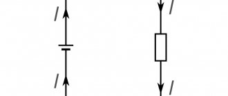
- We connect the tester into a break in the chain of the circuit branch, not forgetting to observe the polarity.
- Turn on the energy source.
If there are no values, the range is most likely selected incorrectly. Try lowering it until you see a reading.
See how to measure amperes with a multimeter:
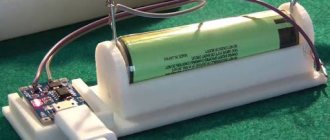
How to measure amperage with a battery-powered multimeter
It is a simple portable power source and does not require the application of a load. Apart from this, the remaining steps are the same: select the desired function on the multimeter, arrange the probes in accordance with the polarity.
What the readings may indicate:
- 4-6 A - everything is fine.
- Below four - the battery is only suitable for use in low-power devices.
- Below 2.5 A - this battery is asking for trash.
Compare the readings with those written on the batteries.
Watch a useful video on how to measure battery amperes with a multimeter:
How to check the current of a battery with a multimeter
The rule here is with a load element, which can be a simple incandescent light bulb. Most likely, its resistance will be no more than several hundred Ohms. How to check the load with a multimeter? Tester, selecting the desired mode. For example, read more about checking resistance with a multimeter here.
Then use this formula: I = U / R (I - current A, U - battery voltage, R - light bulb resistance).
Compare the numbers you get when measuring the current with a multimeter with the resulting value. If you see a difference, especially a significant one, it may be a bad charge.
Useful video on how to check amperes with a multimeter:
Problems with the rotary switch
Repair will be required if problems arise due to loss of contact in the circular biscuit switch. This manifests itself not only in the fact that the multimeter does not turn on, but also in the inability to obtain a normal connection without pressing hard on the biscuit. This is explained by the fact that in cheap Chinese multimeters, the contact tracks are rarely covered with high-quality lubricant, which leads to their rapid oxidation.
When used in dusty conditions, for example, after some time they become dirty and lose contact with the switch bar. To repair this multimeter assembly, it is enough to remove the printed circuit board from its body and wipe the contact tracks with a cotton swab dipped in alcohol. Then a thin layer of high-quality technical Vaseline should be applied to them.
In conclusion, we note that if contacts are detected or shorted in the multimeter, these shortcomings should be eliminated by using a low-voltage soldering iron with a well-sharpened tip. If you are not completely sure of the cause of the device failure, you should contact a specialist in the repair of measuring equipment.
Multimeter DT-830C does not display voltage correctly
- Author
- Message
Multimeter DT-830C does not display voltage correctly
Re: Simple human weaknesses
Re: Simple human weaknesses
Re: DT-830C multimeter displays incorrect voltage
It is useful to start any repair by measuring the voltages in the sensitive components of the circuit. Judging by the specification for the ICL7106 “drop” on which all these multimeters are built, here this is the reference voltage VREF HI, which should be 100 mV at the REF HI pin.
DOMOSTROYPlumbing and construction
- home
- Connect with us
- Thursday, December 12, 2022 1:08
- Author: Sereg985
- Comment
- Category: Construction
- Link to post
- https://firmmy.ru/
Organizing and repairing a multimeter independently is within the capabilities of every user who is well acquainted with the basics of electronics and electrical engineering. But before you begin such repairs, you need to try to understand the nature of the damage that has occurred.
What it is
An electrical measuring instrument that combines a voltmeter, an ohmmeter and an ammeter in one housing is correctly called a multimeter, multitester or ampere-voltmeter. Even in everyday life you can hear such names as “tester” or “tseshka”. It is capable of measuring AC and DC voltage, resistance, and current.
They also measure the capacitance of capacitors, “ring” diodes and transistors, and determine the safety of the electrical network.
Testers are both analog (with arrows) and digital (with a screen). Digital ones are more accessible and easier to use, but the measurement principle is the same for both types.
The full range of measurements that a multimeter can perform is needed when assembling electrical circuits, repairing household and industrial electrical appliances, and requires a highly qualified specialist. At the same time, such an irreplaceable thing can also be used in everyday life, for example, for simple work on a household 220-volt electrical network.
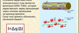
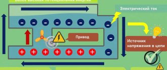
What is current and why measure it?
This is the amount of electricity (charge or number of electrons) that moves through the cross section of a conductor in one second. In formulas it is denoted by the capital Latin letter I. The unit of current is Amperes (A).
Current strength is often referred to simply as current. It comes in two types:
- Constant. The current does not change in direction or magnitude. That is, this is a uniform directed movement of charged particles. Formula for calculation: I=Δq/Δt ( Δq(C) is the charge in Coulombs that passed through the cross section; Δt(c) is the time during which the charge passed).
- Variable. This is a current in which even one characteristic changes. It differs at different points in time. To calculate such a current, it is better to use the derivative.
It is generally accepted that a current of 1 A is generated in a conductor with a resistance of 1 ohm if there is a voltage of 1 V.
Checking the current with a multimeter is needed for:
- Clarification of the actual power consumption of the electrical unit.
- Detecting defects in electrical devices if its power is less than that declared by the manufacturer.
- Determination of the electrical capacity of autonomous energy sources, for example, batteries.
- Detection of current leakage in electrical circuits.
Ammeters are often used to determine current or amperage. But, if you have a multimeter with this function, feel free to use it.
Here's a video on how to measure current with a multimeter:
Why do you need to take measurements?
The electrical network is a dangerous and complex engineering system that requires operational skills and safety.
For a number of reasons, malfunctions and breakdowns may occur. To control and prevent them, it is necessary to carry out measurements. Also, breakdown or unstable operation of electrical appliances and equipment can be caused by a discrepancy between the mains voltage and the nominal voltage, and both excess and insufficient voltage can be dangerous.
What needs to be done to avoid overloading the electrical system - this can be achieved through the correct use of electrical equipment and measurements. Using a multimeter, you can determine the necessary parameters yourself, without involving qualified electrical laboratory specialists.
What voltage standards exist?
Existing standards for the operation of electrical systems describe voltage values as applied to residential premises. According to GOST, the normal voltage in residential buildings is 220V +/- 10%. Therefore, household electrical appliances are usually designed for voltages up to 240 volts.
Note! When this value rises above the required level or decreases beyond the permissible percentage, you need to disconnect all electrical appliances from the power supply and check the exact voltage parameter.
To assess the electricity at the input (for example, near the meter), that is, that which comes in “from the street” and is not influenced by powerful energy consumers or long electrical wiring, there are several parameters.
Unfortunately, a multimeter can only determine one, but the most important one is permanent deviation. This deviation during normal operation should not be more than 5% of the rated voltage value for a long period of time and rise above 10% for a short period. These parameters are set by the service provider and are reflected in the service agreement. Most likely, this is a corridor installed within 198-220 volts.
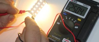
How to check the voltage in a 220V network with a multimeter?
How to check voltage with a multimeter? It's worth preparing it. Place the plug of the black wire into the connector marked COM. Place the red one in the connector marked VΩmA.
Around the mode switch are indicated the maximum values, for example, 200 and 500 volts, as well as the type of current: alternating or direct. The first one is marked with a V
(ACV - symbols on the body may vary). You need to set the pointer to 500. If the value is less than or approximately equal to the measured value, the tester has a chance of breaking due to overload. When the multitester screen is reset to zero, it can measure. Take two probes that end the wires connected to the indicated connectors. Plug them into a socket or touch the wires. It doesn’t matter which probe goes where: the voltage is alternating. The display will show approximately 220 volts if there is current in the network, or zero if there is none.
If it is necessary to find the phase and neutral wires (this is necessary, for example, for the correct installation of a switch), set the wires in the same way as in the previous case and the same value V
and 500 volts. Next, the red probe is used to touch the conductor being tested, and the black one is pinched with the fingers or placed against a guaranteed grounded structure. For phase the value will be about 220, if zero - freeze at 0 or a little more, up to 127. The danger of electric shock is minimal, but the device must be in working order and the parameters are set correctly.
Testing wires with a multimeter
Measuring voltage
In this chapter we will look at how to use a multimeter to check the integrity of wires or, as they say, for continuity. When is this operation needed? Very often. For example, when something doesn’t work and you need to determine whether the cord is to blame. This is the first step when repairing any household appliance - checking the integrity of the power cord. And the test is carried out using a multimeter (tester) in dialing mode.
The second most common case is when, when connecting a cable, they forgot to label which wire they connected where. In this case, the probe is held at one end on one wire, and at the other end the conductors are sorted until a characteristic sound is heard.
Now about the procedure itself. First, we switch the switch to dialing mode. In this mode, the device emits a squeak if the circuit resistance is less than 50 Ohms. If you connected the device to both ends of the conductor and heard a squeak, the wire is intact; if there is no squeak, there is a break somewhere.
Typically, the dialing mode on multimeters is depicted graphically: a pictogram is applied in the form of a horn with outgoing sound waves. We put the switch in this position, set the probes to the standard position - red in the “COM” socket, black in VΩmA. With the free ends of the probes we touch the ends of the wire being tested. When testing the cable, this procedure is repeated with each core.
Safety precautions
- You should definitely read the instructions for the device.
- Avoid touching parts with your fingers. The human body has its own resistance, which can affect the accuracy of the measurement.
- You need to wear non-conductive gloves when measuring. If there are none, dense rubberized models are suitable.
- If there is high humidity at the measurement site, it should not be carried out.
- When a measurement is being taken, modes cannot be switched.
- In case of mechanical damage or deformation of the braiding of wires and probes, the device cannot be used.
Multimeter, an affordable and simple device for home use. It allows you to accurately measure parameters. This contributes to safe and convenient work with the electrical network, and also ensures the serviceability of household appliances.
{SOURCE}
Error – Switching at the moment of measurement
It is strictly prohibited to switch the measurement range wheel directly during measurements.
It is because of such switching that the tracks in the switch area most often burn.
To move the device to another position, the probes (or at least one probe) must be disconnected from the object being measured.
Most often, this error is observed when there are “crocodiles” on the probes.
Read also: Cupcake with whipped cream
At the same time, your hands are freed and automatically reach for the switch.