One type of lifting mechanisms are various types of elevators. They are designed to transport people or goods by lifting or lowering. To move the cabin, fixed rigid guides are used, installed in the shaft in a vertical position. Normal operation of all systems is ensured using special electrical equipment. Therefore, for such devices, a general electrical circuit diagram of the elevator has been developed to ensure their reliable operation.
Control circuits for electric drives of elevators
Depending on the speed of passenger elevators, the following types of power control circuits are adopted:- low-speed elevators have squirrel-cage or wound-rotor motors and push-button or lever controls,
- high-speed elevators - two or single-speed motors controlled by magnetic stations or thyristor control stations (TSU-R) with push-button command devices,
- high-speed and high-speed elevators - DC motors controlled by the “generator-motor” system with various excitation circuits or by the “thyristor converter-motor” system with push-button command devices,
- Asynchronous valve cascade (AVC) circuits can also be used, the use of which allows increasing efficiency. installations.
Passenger elevators, depending on passenger flow, lift height and the number of elevators serving passengers, are divided into single and group-controlled.
Singles include:
a) elevators operating according to single orders and calls without passing stops when descending and ascending passengers,
b) elevators with the collection of passengers during descent, but with the prohibition of calls during ascent,
c) the same, but with registration of calls on descent and their subsequent execution.
Group controlled elevators include:
a) elevators with one call button on the landing areas, regardless of the number of installed elevators (pair control is more often used) and with the collection of passengers during descent,
b) the same, but with full collection of passengers on intermediate floors for ascent and descent (usually installed in administrative, educational and other buildings).
In addition, elevator dispatching of a number of buildings and entire areas is very often used, when the status of circuits is monitored from one dispatch console and several elevators are controlled.
Regardless of the speed of elevators, single or group control of them, the necessary elements of most of their schemes are the following:
- self-resetting buttons, sticky or stuck buttons for calling booths and giving orders from the booth,
- various selection and precise stop sensors - positional matching devices for recording the location of the cabin and the state of electrical circuits,
- sensors and locks for the state of lifting ropes, the state of the shaft and cabin doors (open or closed),
- limit switches for limiting speed and cabin load,
- indicators of the direction of movement of the cabin and in some elevators the presence of cargo in the cabin.
Of the above-mentioned elements, we will dwell in more detail on position-matching devices (PSU), which determine the place where the cabin should stop in the shaft when a call or order appears, and its movement up or down. The remaining elements usually represent various modifications of limit switches known from other courses.
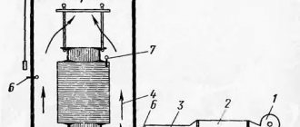
Structurally, position-matching devices are made in the form of a set of three-position electromechanical or inductive or magnetic (reed switch) sensors located in shafts, with signals output to a relay or contactless selector in the machine room (PSUs are sometimes made in the form of central floor devices located in the machine room) .
Sensors placed in the shaft interact with taps installed on the cabin (for electromechanical ones) or magnetic shunts (for inductive or reed sensors) and issue signals to the central floor device (stepper machine or relay selector) installed in the machine room, and the latter transmits and control circuit - a signal to execute the received command.
It is more expedient to place sensors for signals about the movement of the cabin up or down on the cabin (fewer wires are required), and magnetic shunts are installed in the shafts at the required points. In this case, with digital control, the number of columns of installed shunts along the shaft is equal to the number of digits of the transmitted floor number in binary or other code.
Three-position electromechanical switches are moved by a figured tap to one of the positions corresponding to the movement of the cabin up or down, or its stop. In this case, when the cabin moves, the contacts of the switches of the passed floors are switched to one of the extreme positions, preparing the chains of calls and orders for action, and when the cabin stops, the switch is moved to the middle position, disconnecting the control circuit from the direction contactors and thereby preventing the cabin from leaving the floor when erroneously pressing the order or call button.
To ensure relatively accurate stopping of the elevator car, non-contact inductive or contact sealed magnetically controlled (reed switch) sensors have recently begun to be used in their control circuits. These sensors are installed both in the shaft and on the cabin: in the shaft there are selection (deceleration) sensors, and on the cabin there is a precise stop sensor. To interact with the sensors, a ferromagnetic selection shunt is placed on the cabin, and ferromagnetic precision stopping shunts are placed in the shaft (on each floor).
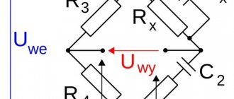
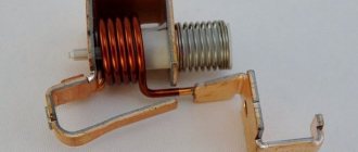
Inductive sensors consist of an open U-shaped magnetic circuit with a coil enclosed in a casing. The executive relay coil is switched in series with it, and alternating current voltage (U) is supplied to them.
When the magnetic circuit is open, the magnetic flux crossing the coil is small. Therefore, the e.m.f. and the self-induction current in the coil conductors, as well as the inductive resistance (X) caused by it, are practically absent, so the coil resistance is active in nature (R). The current in series-connected coils is relatively large; it seems to simulate the closure of contacts in the contact system (the relay turns on).
When a U-shaped magnetic circuit is closed by a shunt, the magnetic flux crossing its coil increases, and therefore the emf increases. self-induction, as well as the resulting inductive reactance of the coil. As a result, the current in the series-connected coils decreases, simulating the opening of the circuit in the contact system (the executive relay is turned off).
The reed switch sensor is a U-shaped housing in which two sealed glass flasks with a vacuum inside and contacts mounted on spring plates, connected to the corresponding elevator control circuits, are placed on one side of the groove. On the other side of the groove there is a permanent magnet. The working element of such sensors is a ferromagnetic shunt, which passes through a U-shaped cut when the elevator car moves.
The operating principle of these sensors is as follows: the springing forces of the reed switch contact plates are directed in such a way that if the field of a permanent magnet does not act on them, then the normally open contacts are open, and the normally closed contacts are closed, i.e. the circuits to which these contacts are connected will be open or closed.
This state of the reed switch will occur when the ferromagnetic shunt is in the groove of the U-shaped housing, since the magnetic field lines of the permanent magnet are closed through the shunt. After the shunt leaves the groove, the magnetic lines of force are closed through the plates, overcoming their springing action, and the reed switch contacts, and therefore the circuits to which they are connected, go into the opposite state.
As an example reflecting the main features of elevator control circuits, consider the control circuit for a single elevator without passing stops, shown in Fig. 1. The elevator serves four floors; a two-speed asynchronous motor M is used as an executive motor.
Switching on to a low (Ml) or high (B) engine speed is carried out by the corresponding contactors Ml and B. The direction of motor rotation is determined by contactors B and N, deceleration by an additional resistor R, braking by an electromagnetic brake ET.
Non-contact inductive sensors (DTS, DTOV and DTON) connected in series with relay coils (RIS, RITOV, RITON) are used as floor switches. The DTS sensors are used to turn on the elevator drive at a high rotation speed and supply an impulse to slow it down, and the DTOV and DTON sensors are designed to accurately stop the elevator at the floor level of the corresponding floor and are placed on the cabin; magnetic shunts for them are installed in the shaft shaft.
Rice. 1. Schematic diagram of single elevator control
We will consider the purpose of the remaining elements of the circuit and its operation using the example of moving a cabin with a passenger from the 1st to the 3rd floor, assuming that the machine A, disconnector P and limit switches KB, limiting the movement of the cabin up and down in emergency modes, are closed , and the cabin is on the first floor. In this case, the coils of the RIS relay, except the first floor relay, are flown with the rated current.
When you press the “3rd floor” button, the following electrical circuit is formed: network phase - disconnector pole P - fuse Pr - limit switch KB - "Stop" button - shaft door locks Dv1 - Dv4 - rope tension contacts KK - limit switch of the CL catcher - door switches of the DK cabin - contacts of the "Stop" button - opening block contact N - relay coil RUV - closing contacts of the RIS4 and RISZ relays (the coils of these relays are flown with current) - floor relay coil ERZ - button "3rd floor" - disconnecting block - contacts of contactors U, B, N - limit switch KB - fuse Pr - pole of the disconnector P - network phase.
After the RUV and ER3 relays are activated, the forward movement contactor B and the fast movement contactor B are switched on (via the coil circuit B - block contact Ml - high-speed switch VB - relay contacts RISZ and ER3). When contacts B and B are closed, the engine is connected to the network, the contactor T is turned on, releasing the traction pulley, and the tapping contactor KO, which turns on the tapping electromagnet MO and prepares the coil circuit of the low-speed contactor Ml for switching on. The lever retracts, releasing the lock lever, and the cabin begins to move.
When the cabin approaches the third floor, the ferromagnetic shunt closes the coil of the DTSZ sensor, its resistance increases and the RISZ relay disappears, turning off the ER3 and RUV relays. As a result of this, contactor B disappears, closing its contact, turns on the low-speed contactor Ml, and contactor B remains on, since when the cabin moves, the magnetic circuit of the up precision stop sensor is not yet closed, therefore the RITOV contact is not yet open. The engine is braked to a low rotation speed, operating in generator mode with resistor R inserted into one stator phase. The braking time delay is set by a pendulum relay RM, which operates when the contactor Ml is turned on.
As soon as the cabin floor is leveled with the floor floor, the magnetic shunt closes the magnetic circuit of the DTOV precision stop sensor coil, the RITOV relay disappears and contactors B are switched off, then KO and, finally, Ml. As a result, the engine and brake electromagnet are disconnected from the network, a mechanical brake is applied and the cabin stops.
In order to learn a collective elevator control scheme with passing stops only when lowering the cabin, or a completely collective circuit, i.e., with passing stops while the cabin is moving up and down, it is necessary to use a circuit similar to that discussed in Fig. 1, introduce some additions. For example, in a circuit with a two-speed motor, inductive ID sensors, RIS relays and call and order buttons on each floor are switched on as shown in Fig. 2.
Rice. 2. Fragments of additions to collective elevator control diagrams (for one floor)
In the circuit with passing stops when lowering the cabin (Fig. 2, a), calls and orders are given by separate sticky buttons and therefore can be registered at any time and transmitted to the circuit immediately, except for the period when the cabin with passengers is moving upward, when the power bus of the transmission contacts calls to the executive circuit are disconnected by selective contacts from the positive bus.
In the complete selective control circuit (Fig. 2, b), there are additionally ringing circuits for raising (ШДВв) and lowering (ШДВн) the cabin; the contacts of the direction blocking relays RBV and RBN are connected to the contacts of the selective sectioned chain of the executive circuit.
In the diagrams shown in Fig. 1 and 2, in the absence of a cabin on the floor, the coils of the inductive ID sensor and the RIS relay are excited. Therefore, when you press the command button or call the CV (they are held in the on state by the holding magnets of the UM until they are bypassed by the contacts of the shaft doors of a given floor of the DS), a circuit is formed (not shown in the figures), including the up control relay RUV, if the destination floor is higher than the cabin parking floor, or the control relay is downward for the RC, if the destination floor is below the cabin parking lot.
After the cabin arrives at the call floor, the inductive ID sensor is de-energized, the RIS relay is turned off, opening its contacts, which turn off the RUV or RUN relay and the LS lamp (the cabin stops), and by closing the RIS4 contact, a circuit is prepared to carry out the order coming from the cabin.
In a complete collective circuit, the chain on the parking floor of the cabin, sectioned by contacts RIS1 and RIS2, is broken not only by these contacts, but also by the contacts of the blocking relay up RBV or down RBN (their coils are not shown in the diagram), and the calling circuits of ascent, descent and order chains are separated from each other by dividing diodes D1 - D4.
Before pressing the call or order button, if the direction of movement of the cabin has not yet been selected, all contacts in the direction selection chain are closed, except for the RIS4 contacts on the parking floor of the cabin. Therefore, when one of these buttons is pressed, call signals from floors located above the cabin parking floor are connected to the RUN relay coil, and call signals from floors below the cabin parking floor turn on the RUV relay. After selecting the direction, simultaneously with the RUV or RUN relay, one of the opposite direction blocking relays RBV or RBN is turned on, breaking with its contacts the output through the sectional chain of signals for calling the opposite direction.
In the diagram shown in Fig. 2, a, to lower passengers, the cabin passes without stopping to the highest call floor and then lowers with passing stops, and in the diagram shown in Fig. 2, b, if it is necessary to lift passengers, the cabin goes to the lowest call floor, after which it rises with passing stops.
In the considered circuits, the selectors are made on relay elements. Along with this, other selectors are used: cam, photoelectric, continuous tracking brush, stepper, static elements, etc.
In case of large passenger flows, several elevators are installed in one hall, which have combined pair or group control to increase comfort and improve energy efficiency. The number of elevators connected in groups usually does not exceed four, and more often than not three, although systems containing up to eight elevators in a group are known.
In group control, there are usually three main operating modes for elevators: peak ascent, peak descent, and balanced movement in both directions. Elevators are switched on to one mode or another by a dispatcher or automatically by means of a programming clock installed on each group of elevators.
In high-rise buildings, each group of elevators is assigned to serve a specific zone of floors; other floors are not served by it. If there are several elevators in a group serving one area or a low building, in order to increase the average speed of movement by reducing the number of stops, separate elevators can be allocated to serve even and odd floors.
To implement paired or group control of elevators, their control circuits must be collective, and calls from each floor in both directions must be registered separately in each direction by appropriate storage devices containing relays, transistors, etc.
As an example reflecting the specifics of operation in paired control of elevators with additional parking relays for the first elevator 1PC and the second elevator 2PC, consider a fragment of the circuit diagram shown in Fig. 3.
Rice. 3. Fragment of the principle diagram of paired elevator control: ER - floor relay, RPK - channel switching relay, RVP automatic start relay
In this case, the cabin, which has descended with passengers on the first floor, does not respond to calls from other floors and waits for passengers. If there is no cabin on the ground floor, then the cabin that has risen by order and become vacant is automatically sent to the first floor, and when another cabin descends or is parked, the latter remains on the end of the flight floor or is directed to the load center and is used to work on calls mainly in the direction lowering.
The parking relay for the cabin on the ground floor 1RS1 or 2RS1 is turned on after the cabin arrives on the first floor from the limit switch 1KVN or 2KVN (installed in the shafts on the copying machine). These relays are mutually interlocked. Therefore, the inclusion of one of them indicates that this cabin arrived on the first floor before the other. In this case, relay 1PC1 or 2PC1 turns on the LS signal lamp with its closing contact, and with its opening contact it breaks the calling circuit of its elevator, turning off the call while the cabin is parked on the first floor.
When a cabin leaves the first floor, its LS signal lamp goes out, the power to the called circuits of this elevator is immediately restored after the cabin is released, and after a cabin of another elevator arrives on the first floor, its PC relay turns on. This cabin remains standing on the ground floor waiting for passengers (which is signaled by the ignition of its LS signal lamp). When the cabin that has risen by order is released and there are no calls, a signal is sent to the circuit, which turns on the 1RUN or 2RUV relay coils of the 1RUN or 2RUV relay by the opening contacts of the limit switch 1KVN or 2KVN, and the cabin is directed to the first floor, etc.
The motor control equipment for standard elevators for single, pair and group control is usually located on standard panels, stations or control units installed in machine rooms.
Source
Story
The first elevators were driven by a steam engine and controlled by an operator. In 1924, Otis introduced the first automatic elevator controlled by logic relays. This made it possible to increase the speed of movement of the cabin. Thirteen years later, Otis showed a system to help schedule elevator operation during periods of high load. This is what the first automatic elevators looked like:
In 1948, Otis began producing automatic elevators that could already change speed, adapt their schedule to periods of load, and not stop when the cabin was fully loaded. They now have a function for automatically closing the door after a certain period of inactivity.
Relay control was used until the 1980s, when they began to be replaced by microprocessors. Microprocessors used less power and took up much less space.
This is what the Otis elevator relay control system looked like. Picture from the site
The importance of lifting machines
In general, the elevator in most cases is not perceived by people as a complex and important device. However, in fact, this invention plays a huge role in our daily life and is a rather complex and well-thought-out device. As for the role of the elevator, it is difficult to overestimate it - every day the world's elevators move about a third of the planet's population, while this type of transport remains the safest today. As for the underestimation of the elevator design, that is a different story. Many people think that an elevator is an extremely simple device, which consists of a cabin and a cable, but this is far from the case.
The first elevators in history were indeed very primitive, however, despite the simplicity of the idea of the elevator, today it represents a whole system of mechanisms and devices necessary not just for lifting, but for high-quality, accurate, fast and safe work.
Characteristics of elevator facilities
The main technical parameters that characterize the operation of the elevator are:
- speed of vertical movement of the cabin;
- load capacity;
- the number of floors, which determines the number of elevator stops;
- maximum lifting height.
Regulatory documents that regulate the requirements for the characteristics of elevator equipment are PUBEL (Rules for the Design and Safe Operation of Elevators) and specialized GOSTs. They also regulate the requirements for servicing elevator facilities.
Key characteristics include elevator speed and lifting capacity. There are several types of speed.
The manufacturer indicates the nominal speed value in the instructions for the lifting equipment. It is provided under optimal operating conditions for a specific elevator model. Typically its value is from 0.18 to 4 m/s. To equip high-rise buildings, high-speed elevators with a nominal speed of 9.5 m/s and higher are used. For a significant number of floors, for example in skyscrapers and high-rise towers, an express system is often used. It provides that high-speed elevators, when ascending, begin to stop only from a certain floor, for example, from the 10th. Below this level, conventional elevators operate at standard speed ratings.
The working speed is considered to be the speed at which the cabin actually moves under the existing conditions at a particular facility. The value depends on the actual load, the level of mains voltage, the condition of mechanical components, the friction acting in them and other criteria. Thus, the operating speed is influenced by the condition of the elevator structure, compliance with the requirements for its operation and maintenance. The provisions of PUBLEL stipulate that the operating speed should not differ from the nominal speed by more than 15%.
The limit is the speed of the cabin at which the safety system's stopping devices are triggered - catchers or parachutes that stop the cabin. Elevator safety devices must not allow the car to accelerate beyond the limit value.
Before arriving at the floor specified by the passenger, the cabin must move at a stopping speed. Its value is reduced compared to the working value in order to eliminate a sudden stop that poses danger or discomfort to passengers. Old-style elevators have two speed settings. The elevator travels the main part of the route at the operating speed, and before stopping it switches to the stopping speed. Modern models use smooth adjustment using frequency electronic regulators. They smoothly increase engine speed at start and smoothly reduce them before the cabin stops. This mode is more comfortable for passengers. In addition, wear is reduced and engine life is increased.
Load capacity is the maximum permissible weight of the cargo transported in the elevator according to the passport. This value is indicated without taking into account the dead weight of the cabin itself and its additional equipment. The carrying capacity of standard passenger models is usually 400 kg. Passenger models of elevators with increased load capacity are widely used to equip new residential complexes. Thus, popular models are those that can operate with a load of up to 630 kg. Freight-passenger elevators are usually adapted for loads of up to 1 ton, and freight elevators - up to 5 tons.