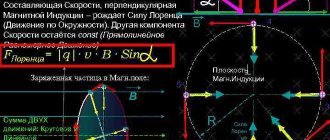
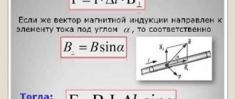
A conductor placed in a magnetic field through which an electric current is passed experiences the influence of Ampere force, and its value can be calculated using the following formula:
(1)
where and are the current strength and the length of the conductor, is the magnetic field induction, and is the angle between the directions of the current strength and magnetic induction. Why is this happening?
A little history
The first attempts to describe electromagnetic force were made back in the 18th century.
Scientists Henry Cavendish and Tobias Mayer proposed that the force on magnetic poles and electrically charged objects obeys the inverse square law. However, the experimental proof of this fact was not complete and convincing. It was only in 1784 that Charles Augustine de Coulomb, using his torsion balance, was able to finally prove this assumption. In 1820, the physicist Oersted discovered the fact that a volt current acts on the magnetic needle of a compass, and Andre-Marie Ampere in the same year was able to develop a formula for the angular dependence between two current elements. In fact, these discoveries became the foundation of the modern concept of electric and magnetic fields. The concept itself was further developed in the theories of Michael Faraday, especially in his idea of lines of force. Lord Kelvin and James Maxwell added detailed mathematical descriptions to Faraday's theories. In particular, Maxwell created the so-called “Maxwell field equation” - which is a system of differential and integral equations that describe the electromagnetic field and its relationship with electric charges and currents in vacuum and continuous media.
JJ Thompson was the first physicist to try to derive from Maxwell's field equation the electromagnetic force that acts on a moving charged object. In 1881, he published his formula F = q/2 vx B. But due to some miscalculations and an incomplete description of the bias current, it turned out to be not entirely correct.
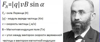
And finally, in 1895, the Dutch scientist Hendrik Lorentz derived the correct formula, which is still used today, and also bears his name, just as the force that acts on a flying particle in a magnetic field is now called the “Lorentz force.”
Hendrik Lorenz.
Concept of electric field strength
The electromagnetic field actually consists of two halves - electric and magnetic. They are like twins, with everything the same, but with different personalities. And if you look closely, you can notice slight differences in appearance.
The same goes for force fields. The electric field also has intensity - a vector quantity, which is a force characteristic. It affects the particles that are motionless in it. In itself, it is not a Lorentz force; it simply needs to be taken into account when calculating the effect on a particle in the presence of electric and magnetic fields.
Useful information and tips
- It is generally accepted that the direction of current points from plus to minus. In fact, in a conductor, the orderly movement of electrons is directed from the negative pole to the positive pole. Therefore, if you were faced with the task of calculating the Lorentz force for an individual electron in a conductor, you should take this circumstance into account.
- By default, we consider a screw (gimlet, corkscrew) with a right-hand thread. However, we should not forget about the existence of screws with left-hand threads.
- When using the clockwise rule, we assume that the arrows move from left to right. It is known that in the former USSR watches with a reverse movement of the clock mechanism were produced. Perhaps such models exist to this day.
It is useful to know that when the gimlet rotates along the direction of rotation of the body, the trajectory of its screwing in will coincide with the direction of the angular velocity.
- https://odinelectric.ru/knowledgebase/sila-lorenca-i-pravilo-levoj-ruki-dvizhenie-zarjazhennyh-chastic-v-magnitnom-pole
- https://intech-irk.ru/tehnika/pravilo-pravoj-ruki.html
- https://www.asutpp.ru/pravilo-buravchika-prostym-yazykom.html
- https://electric-220.ru/pravilo-levoj-ruki
- https://seti.guru/pravilo-pravoy-i-levoy-ruki-v-fizike-primenenie
Fundamentals of the special theory of relativity (STR)
To the table of contents...
Relativistic length reduction:
Relativistic extension of event time:
Relativistic law of addition of velocities. If two bodies are moving towards each other, then their speed of approach is:
Relativistic law of addition of velocities. If bodies move in the same direction, then their relative speed is:
Body resting energy:
Any change in body energy means a change in body weight and vice versa:
Total body energy:
The total energy of the body E is proportional to the relativistic mass and depends on the speed of the moving body; in this sense, the following relationships are important:
Relativistic mass increase:
Kinetic energy of a body moving at relativistic speed:
There is a relationship between the total energy of the body, rest energy and momentum:
Using the right hand rule in electrodynamics
If you hang a frame with current in a magnetic field on a thin and flexible wire, it will rotate and be positioned in a certain way. The behavior of a magnetic needle is similar. This indicates the vector nature of the physical quantity characterizing the magnetic field. In this case, the direction of this vector will be related to the orientation of the frame and arrow. The physical vector quantity that characterizes the magnetic field is the magnetic induction vector ($\vec{B}$).
Are you an expert in this subject area? We invite you to become the author of the Directory Working Conditions
This is one of the main parameters that describe the state of the magnetic field, so you need to be able to find its magnitude and, of course, direction.
To determine the direction of the magnetic induction vector, use:
- right screw rule or
- right hand rule.
The direction of the magnetic induction vector, at the location of the frame with current, is considered to be the direction of the positive perpendicular ($\vec{n}$) to this frame. The positive normal ($\vec{n}$) will have the same direction as the direction of translational movement of the right screw if its head is rotated along the current in the frame (Fig. 1 (a)).
Figure 1. Determination of the direction of the magnetic induction vector. Author24 - online exchange of student work
Thus, having a test frame with current, placing it in the field under study, allowing it to rotate freely in it, you can determine the direction of the magnetic induction vector at each point in the field. You just need to let the frame come to a balanced position, then use the right screw rule.
Finished works on a similar topic
Course work Rule of the left and right hand for a magnetic field 490 ₽ Abstract Rule of the left and right hand for a magnetic field 270 ₽ Test paper Rule of the left and right hand for a magnetic field 200 ₽
Receive completed work or specialist advice on your educational project Find out the cost
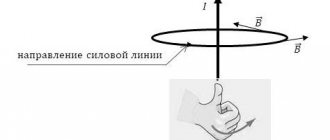
Now let's look at the right hand rule. Let's clench our right hand into a loose fist (Fig. 2). Bend your thumb 90°. Let's place the hand so that the thumb indicates the direction of current flow, then the bent other four fingers will indicate the direction of the lines of magnetic induction of the field that creates the current. And we remember that the tangent at each point of the field to the field line (magnetic induction line) indicates the direction $\vec{B}$.
Figure 2. Right hand rule. Author24 - online exchange of student work
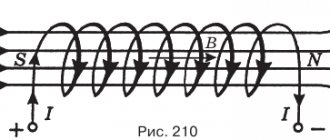
Let's consider a solenoid. Let's clasp it with our right palm so that four fingers coincide with the direction of the current in it, then the finger bent ninety degrees will indicate the direction of the magnetic field created inside it.
We know that if a conductor is moved in a magnetic field, an induction current will arise in this conductor. The right hand rule can be used to determine the direction of flow of induced current in such conductors. Wherein:
- the magnetic field induction lines should enter the open palm of the right hand,
- bend the finger of this hand ninety degrees and direct it according to the speed of movement of the conductor,
- the extended four fingers will indicate the direction of the induction current.
The right-hand rule can be used to determine the direction of the induced emf in a circuit:
With the bent four fingers of your right hand, grasp the contour in which the EMF is induced when the magnetic flux changes, bend the thumb of this hand ninety degrees and direct it in the direction of the magnetic flux when it increases (or against the direction of the magnetic flux when it decreases), then the bent fingers will point in the direction opposite to the EMF.
A magnetic field
In accordance with the above, we can give the following definition of a magnetic field.
A magnetic field is one of the two sides of the electromagnetic field, excited by the electric charges of moving particles and changes in the electric field and characterized by a force effect on moving infected particles, and therefore on electric currents.
| Figure 1. Magnetic field around a current-carrying conductor |
| Figure 2. Direction of magnetic induction lines |
If you pass a thick conductor through cardboard and pass an electric current through it, then the steel filings poured onto the cardboard will be located around the conductor in concentric circles, which in this case are the so-called magnetic induction lines (Figure 1). We can move the cardboard up or down the conductor, but the location of the steel filings will not change. Consequently, a magnetic field arises around the conductor along its entire length.
If you put small magnetic arrows on the cardboard, then by changing the direction of the current in the conductor, you can see that the magnetic arrows will rotate (Figure 2). This shows that the direction of magnetic induction lines changes with the direction of current in the conductor.
Magnetic induction lines around a current-carrying conductor have the following properties: 1) magnetic induction lines of a straight conductor have the shape of concentric circles; 2) the closer to the conductor, the denser the magnetic induction lines are located; 3) magnetic induction (field intensity) depends on the magnitude of the current in the conductor; 4) the direction of magnetic induction lines depends on the direction of the current in the conductor.
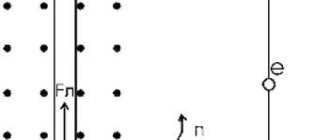
To show the direction of the current in the conductor shown in section, a symbol has been adopted, which we will use in the future. If you mentally place an arrow in the conductor in the direction of the current (Figure 3), then in the conductor in which the current is directed away from us, we will see the tail of the arrow’s feathers (a cross); if the current is directed towards us, we will see the tip of an arrow (point).
Figure 3. Symbol for the direction of current in conductors
Meaning and Definition
The Lorentz force law describes the influence of E and B on a point charge, but such influence does not show the whole picture. Charged particles do not simply drift in a uniform electromagnetic field. They may be subject to other influences, such as gravity. In real materials, the physicist's conclusions are not suitable for describing the collective behavior of such particles, as in principle and for calculation, since bodies not only react to the E and B fields, but also generate them.
Complex transport equations must be solved to determine the temporal and spatial reaction of charges, for example, the equalities:
- Boltzmann;
- Fokker - Planck;
- Navier-Stokes.
For example, to solve questions on hydrodynamics, electrohydrodynamics, superconductivity and evolution of stars, a whole physical apparatus (Green-Kubo formulas) has been developed.
For greater accuracy, it should be clarified that the Lorentz force means the following empirical statement: F on a test charge at a given point and a given time is a specific function of charge q and velocity V, which can be parameterized by exactly two vectors E and B in the form F = q ( E + vx B).
This is true even for particles approaching the speed of light. Thus, two vector fields (magnetic and electric) are determined throughout space and time regarding what force the test charge will receive.
Actually, this is only a definition in principle, because a real particle (as opposed to a hypothetical one) will generate its own finite E and B fields, changing the electromagnetic force it experiences. In addition, when the charge has acceleration, as if it were forced to move along a trajectory curved by some external agents, radiation emits from it, causing deceleration. These effects occur through both direct and indirect effects. Among other things, gravity and other forces must be taken into account.
The effect of a magnetic field on a current. Left hand rule.
Let us place a conductor between the poles of a magnet through which a constant electric current flows. We will immediately notice that the conductor will be pushed out of the interpolar space by the magnetic field.
This can be explained as follows. Around the conductor with current (Figure 1.) its own magnetic field is formed, the force lines of which on one side of the conductor are directed in the same way as the force lines of the magnet, and on the other side of the conductor - in the opposite direction. As a result, on one side of the conductor (in Figure 1 above) the magnetic field turns out to be condensed, and on the other side (in Figure 1 below) it is rarefied. Therefore, the conductor experiences a force pressing down on it. And if the conductor is not fixed, it will move.
Figure 1. Effect of a magnetic field on current.
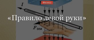
Left hand rule
To quickly determine the direction of movement of a current-carrying conductor in a magnetic field, there is the so-called left-hand rule (Figure 2).
Figure 2. Left hand rule.
The left hand rule is as follows: if you place your left hand between the poles of a magnet so that the magnetic lines of force enter the palm, and the four fingers of the hand coincide with the direction of the current in the conductor, then the thumb will show the direction of movement of the conductor.
So, a force acts on a conductor through which an electric current flows, tending to move it perpendicular to the magnetic lines of force. The magnitude of this force can be determined experimentally. It turns out that the force with which a magnetic field acts on a current-carrying conductor is directly proportional to the strength of the current in the conductor and the length of that part of the conductor that is in the magnetic field (Figure 3 on the left).
This rule is true if the conductor is located at right angles to the magnetic lines of force.
Figure 3. The strength of interaction between the magnetic field and current.
If the conductor is not located at right angles to the magnetic lines of force, but, for example, as shown in Figure 3 on the right, then the force acting on the conductor will be proportional to the current strength in the conductor and the length of the projection of the part of the conductor located in the magnetic field, onto a plane perpendicular to the magnetic lines of force. It follows that if the conductor is parallel to the magnetic lines of force, then the force acting on it is zero. If the conductor is perpendicular to the direction of the magnetic lines of force, then the force acting on it reaches its greatest value.
The force acting on a current-carrying conductor also depends on magnetic induction. The denser the magnetic field lines are, the greater the force acting on the current-carrying conductor.
Summarizing all of the above, we can express the effect of a magnetic field on a current-carrying conductor by the following rule:
The force acting on a current-carrying conductor is directly proportional to the magnetic induction, the strength of the current in the conductor and the length of the projection of the part of the conductor located in the magnetic field onto a plane perpendicular to the magnetic flux.
It should be noted that the effect of a magnetic field on a current does not depend either on the substance of the conductor or on its cross-section. The effect of a magnetic field on a current can be observed even in the absence of a conductor, passing, for example, a stream of rapidly rushing electrons between the poles of a magnet.
The effect of a magnetic field on current is widely used in science and technology. The use of this action is based on the design of electric motors that convert electrical energy into mechanical energy, the design of magnetoelectric devices for measuring voltage and current, electrodynamic loudspeakers that convert electrical vibrations into sound, special radio tubes - magnetrons, cathode ray tubes, etc. The action of a magnetic field Current is used to measure the mass and charge of an electron and even to study the structure of matter.
Related materials:
- Magnetic field of current. Magnetic lines of force
- Magnetic field strength
- Magnetic induction
- Electromagnetic induction
- Right hand rule
- Mutual induction
- Self-induction
- Self-induction EMF: basic postulates
- Permanent magnets
Comments
Gromova Eva 02.27.2018 18:58 Thank you very much for the article!
Quote
Asaev Anton 09/04/2014 04:56 thanks to the creator of the site
Quote
Update list of comments
Wide Application
The first instruments for the proposed discoveries were cyclotrons. The meaning of their work is quite simple: the particles move in a semicircle. Every time they pass a certain area, a special module turns on an electric field to speed them up.
Mass spectrometers are used to identify atoms and molecules. They are used in the following devices:
- electric motors;
- loudspeakers;
- rail guns.
The ability of the Lorentz force to couple mechanical displacement to electrical current is of great interest in medical acoustics. For example, a hydrophone was being developed to map the velocity of particles in an acoustic field. It was supposed to be built using thin copper wire and an external magnetic field.
The model was developed to determine the relationship between acoustic pressure and the measured electrical current that is induced when a wire vibrates in the acoustic field of an ultrasonic transducer.
The created prototype was characterized. Its spatial resolution, frequency response, sensitivity, reliability and directivity characteristics were investigated. An imaging technique called electrical impedance tomography has also been studied. In this method, biological tissue is vibrated with ultrasound in a magnetic field, which induces an electric current. This method was applied to image a gelatin phantom, a beef muscle sample, and a thermal lesion in a chicken breast sample. This showed that the technique could be useful in providing additional contrast compared to conventional ultrasound imaging.
Application of Lorentz force in technology
Kinescope
The kinescope, which was installed until recently, when it was replaced by an LCD (flat) screen, in every TV, would not have been able to work without the Lorentz force. To form a television raster from a narrow stream of electrons on the television screen, deflection coils are used, in which a linearly varying magnetic field is created. Line coils move the electron beam from left to right and return it back; frame coils are responsible for vertical movement, moving the beam running horizontally from top to bottom. The same principle is used in oscilloscopes - devices used to study alternating electrical voltage.
Watch this video on YouTube
Mass spectrograph
A mass spectrograph is a device that uses the dependence of the radius of rotation of a charged particle on its specific charge. The principle of its operation is as follows:
A source of charged particles that gain speed using an artificially created electric field is placed in a vacuum chamber in order to eliminate the influence of air molecules. The particles fly out from the source and, having passed along a circular arc, hit the photographic plate, leaving marks on it. Depending on the specific charge, the radius of the trajectory and, therefore, the point of impact changes. This radius is easy to measure, and knowing it, you can calculate the mass of the particle. Using a mass spectrograph, for example, the composition of lunar soil was studied.
Cyclotron
The independence of the period, and therefore the frequency of rotation of a charged particle from its speed in the presence of a magnetic field, is used in a device called a cyclotron and designed to accelerate particles to high speeds. A cyclotron is two hollow metal half-cylinders - dees (each of them resembles the Latin letter D in shape), placed with straight sides facing each other at a short distance.
The dees are placed in a constant uniform magnetic field, and an alternating electric field is created between them, the frequency of which is equal to the frequency of rotation of the particle, determined by the magnetic field strength and specific charge. Falling under the influence of an electric field twice during the rotation period (when moving from one dee to another), the particle accelerates each time, increasing the radius of the trajectory, and at a certain moment, having gained the required speed, flies out of the device through the hole. In this way, a proton can be accelerated to an energy of 20 MeV (megaelectronvolt).
Magnetron
A device called a magnetron, which is installed in every microwave oven, is another representative of devices that use the Lorentz force. The magnetron is used to create a powerful microwave field, which heats the internal volume of the oven where the food is placed. The magnets included in its composition correct the trajectory of electrons inside the device.
Earth's magnetic field
And in nature, the Lorentz force plays an extremely important role for humanity. Its presence allows the Earth's magnetic field to protect people from the deadly ionizing radiation of space. The field prevents charged particles from bombarding the surface of the planet, causing them to change direction.
Coulomb's law, definition and formula - electric point charges and their interaction
Determining the direction of the magnetic induction vector using the gimlet rule and the right hand rule
What is induced emf and when does it occur?
History of the discovery of electricity
How to convert amps to watts and vice versa?
How to connect a single-phase electric motor - circuit with a capacitor
Formulation and formulas
A particle with charge q experiences a force F when it moves with speed v in an electric (E) and magnetic (B) field. It is defined as F = qE + qv x B and is measured in SI units - N (newton). In terms of Cartesian components there are:
- F x = q (E x + ⱴ y B z - ⱴ z B y);
- F y = q (E y + ⱴ z B x - ⱴ x B z);
- F z = q (E z + ⱴ x B y – ⱴ y B x).
E and B are functions of time position. Therefore, the equality can be written as F(r, ṙ, t, q) = q, where r is the position vector of the charged particle, t is time, and overdot is the derivative of time.
The acceleration of the particle will occur in the same linear orientation as the field E, but will begin to bend perpendicular to both the instantaneous velocity vector v and the field B. This indicates the correspondence of the Lorentz force formula and the “left-hand rule”. The "gimlet rule" will also apply here (if the fingers flare out to point towards v and then curl to point towards B, then the thumb will point towards F).
The combination q E is called the electric force, and q (v + B) is called the magnetic force. In this context, it can be called the Laplace force. It does not affect the power because it is always perpendicular to the particle speed.
For a continuous charge distribution in motion, the equation takes the form dE = dq (E + v + B). If both sides of the equation are divided by the volume of a small fragment dV, the result will look like this : f = p (E + vx B). Therefore, the continuous analogue of the equation is f = pE + J x B, where J is the current density.
The total force is the volume integral over the charge distribution: F = ∫∫∫ (p E + J x B) dV. By eliminating p and J, using Maxwell's equations, and manipulating using theorems of vector calculus, this form can be used to obtain the stress tensor σ. This in turn can be combined with the Poynting vector s to produce the electromagnetic energy-momentum tensor T used in general relativity. If you divide the total charge and current into their associated particles, you get the Lorentz force density. This, in turn, can explain the torque.
What is the Lorentz force - definition, when it occurs, obtaining the formula
It is known that electric current is the ordered movement of charged particles. It has also been established that while moving in a magnetic field, each of these particles is subject to the action of a force. For a force to occur, the particle must be in motion.
The Lorentz force is a force that acts on an electrically charged particle as it moves in a magnetic field. Its direction is orthogonal to the plane in which the vectors of particle velocity and magnetic field strength lie. The resultant of the Lorentz forces is the Ampere force. Knowing it, we can derive a formula for the Lorentz force.
The time required for a particle to pass a segment of a conductor, , where is the length of the segment and is the speed of the particle. The total charge transferred during this time through the cross section of the conductor is . Substituting here the time value from the previous equality, we have
(2)
At the same time, where is the number of particles located in the conductor under consideration. In this case, where is the charge of one particle. Substituting the value from (2) into the formula, you can get:
Thus,
Using (1), the previous expression can be written as
After reductions and translations, a formula appears for calculating the Lorentz force
Taking into account the fact that the formula is written for the force modulus, it must be written as follows:
(3)
Since , then to calculate the modulus of the Lorentz force, it does not matter where the velocity is directed - in the direction of the current or against it - and we can say that - this is the angle formed by the vectors of the particle velocity and magnetic induction. Writing the formula in vector form will look like this:
Writing the formula in vector form will look like this:
is a vector product, the result of which is a vector with a modulus equal to .
Based on formula (3), we can conclude that the Lorentz force is maximum in the case of perpendicular directions of the electric current and magnetic field, that is, when , and disappears when they are parallel ().
It must be remembered that to obtain the correct quantitative answer - for example, when solving problems - you should use SI units, in which magnetic induction is measured in teslas (1 T = 1 kg s−2 A−1), force in newtons (1 N = 1 kg m/s2), current strength - in amperes, charge in coulombs (1 C = 1 A s), length - in meters, speed - in m/s.
Determining the direction of the Lorentz force using the left-hand rule
Since in the world of macro objects the Lorentz force manifests itself as the Ampere force, you can use the left-hand rule to determine its direction.
You need to place your left hand so that the open palm is perpendicular and towards the lines of the magnetic field, four fingers should be extended in the direction of the current strength, then the Lorentz force will be directed where the thumb, which should be bent, points.
Motion of a charged particle in a magnetic field
In the simplest case, that is, when the magnetic induction and particle velocity vectors are orthogonal, the Lorentz force, being perpendicular to the velocity vector, can only change its direction. The magnitude of the speed, and therefore the energy, will remain unchanged. This means that the Lorentz force acts by analogy with the centripetal force in mechanics, and the particle moves in a circle.
In accordance with Newton's II law (), the radius of rotation of a particle can be determined:
.
It is necessary to note that with a change in the specific charge of the particle (), the radius also changes. In this case, the rotation period T = =
It does not depend on speed, which means that the relative position of particles with different speeds will remain unchanged
In this case, the period of rotation is T = = . It does not depend on speed, which means that the relative position of particles with different speeds will remain unchanged.
In a more complex case, when the angle between the particle velocity and the magnetic field strength is arbitrary, it will move along a helical trajectory - translationally due to the velocity component directed parallel to the field, and along a circle under the influence of its perpendicular component.
Determining the direction of the Lorentz force using the left-hand rule
Since in the world of macro objects the Lorentz force manifests itself as the Ampere force, you can use the left-hand rule to determine its direction.
You need to place your left hand so that the open palm is perpendicular and towards the lines of the magnetic field, four fingers should be extended in the direction of the current strength, then the Lorentz force will be directed where the thumb, which should be bent, points.
Newton's first law
Drum roll please! Newton's laws describe forces and motion, and his first law states: “An object is in a state of equilibrium or motion in a straight line at constant speed unless subjected to external influence.” Need a translation? If you don't apply a force to an object at rest or in "constant" motion, it will remain at rest or in constant motion in a straight line. And forever!
For example, when playing hockey, the puck, after being hit, moves towards the goal in a straight line, sliding along the ice with almost no friction. If you are lucky, the opponent will not be able to catch the puck with his stick, i.e. will not be able to change the “constant” movement of the puck in a straight line (and prevent a goal).
Newton's first law states only that the only way to change motion is to apply an external force. In other words, force is the cause of motion. It also states that an object in motion tends to stay in motion, which leads to the idea of inertia.
Maintaining motion: inertia and mass
Inertia is the natural tendency of an object to remain at rest or in motion at a constant speed along a straight line. Inertia is caused by mass, and the mass of an object is a measure of inertia. To set an object in motion, i.e. to change its current state of motion, it is necessary to apply force to overcome inertia.
Imagine a dock with a small boat and a large oil tanker. If you try to push them with your foot, the behavior of these ships will be different. The boat will glide across the water surface, and the tanker will barely “shudder” (and even this will require an incredibly strong push!). The fact is that they have completely different masses and therefore different inertia. In response to the same force, an object with low mass (and low inertia) will accelerate more than an object with low mass and high inertia.
Inertia, i.e. the tendency of a mass to remain unchanged in its current state of motion can sometimes be a problem. For example, in a refrigerator, heavy carcasses of frozen meat are suspended from the ceiling of the body. If the refrigerator enters a sharp turn at high speed, the carcasses will begin to swing like pendulums by inertia, and it will be difficult to stop them. Often, inexperienced drivers do not take into account the inertia of meat carcasses, and this leads to tragic consequences, for example, the car overturning.