Resistances in electrical circuits can be connected in series, in parallel, in a mixed circuit, and in star and delta circuits. The calculation of a complex circuit is simplified if the resistances in this circuit are replaced by one equivalent resistance Req, and the entire circuit is represented as a circuit in Fig. 1.3, where R=Req, and currents and voltages are calculated using Ohm’s and Kirchhoff’s laws.
Electric circuit with series connection of elements
Rice. 1.4
Rice. 1.5
A sequential connection is a connection of circuit elements in which the same current I occurs in all elements included in the circuit (Fig. 1.4).
Based on Kirchhoff’s second law (1.5), the total voltage U of the entire circuit is equal to the sum of the voltages in individual sections:
Thus, when connecting circuit elements in series, the total equivalent resistance of the circuit is equal to the arithmetic sum of the resistances of the individual sections. Consequently, a circuit with any number of series-connected resistances can be replaced by a simple circuit with one equivalent resistance Req (Fig. 1.5). After this, the calculation of the circuit is reduced to determining the current I of the entire circuit according to Ohm’s law
,
and using the above formulas, calculate the voltage drop U1, U2, U3 in the corresponding sections of the electrical circuit (Fig. 1.4).
The disadvantage of sequential connection of elements is that if at least one element fails, the operation of all other elements of the circuit stops.
Electric circuit with parallel connection of elements
A parallel connection is a connection in which all consumers of electrical energy included in the circuit are under the same voltage (Fig. 1.6).
In this case, they are connected to two circuit nodes a and b, and based on Kirchhoff’s first law (1.3), we can write that the total current I of the entire circuit is equal to the algebraic sum of the currents of the individual branches:
I = I1 + I2 + I3, i.e. ,
whence it follows that
.
In the case when two resistances R1 and R2 are connected in parallel, they are replaced by one equivalent resistance
.
From relation (1.6), it follows that the equivalent conductivity of the circuit is equal to the arithmetic sum of the conductivities of the individual branches:
As the number of parallel-connected consumers increases, the circuit conductivity geq increases, and vice versa, the total resistance Reeq decreases.
Voltages in an electrical circuit with resistances connected in parallel (Fig. 1.6)
It follows that
,
those. The current in the circuit is distributed between parallel branches in inverse proportion to their resistance.
According to a parallel-connected circuit, consumers of any power, designed for the same voltage, operate in nominal mode. Moreover, turning on or off one or more consumers does not affect the operation of the others. Therefore, this circuit is the main circuit for connecting consumers to a source of electrical energy.
Electric circuit with a mixed connection of elements
A mixed connection is a connection in which the circuit contains groups of parallel and series-connected resistances.
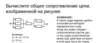
For the circuit shown in Fig. 1.7, the calculation of equivalent resistance begins from the end of the circuit. To simplify the calculations, we assume that all resistances in this circuit are the same: R1=R2=R3=R4=R5=R. Resistors R4 and R5 are connected in parallel, then the resistance of the circuit section cd is equal to:
.
In this case, the original circuit (Fig. 1.7) can be represented in the following form (Fig. 1.8):
In the diagram (Fig. 1.8), resistance R3 and Rcd are connected in series, and then the resistance of the circuit section ad is equal to:
.
Then the diagram (Fig. 1.8) can be presented in an abbreviated version (Fig. 1.9):
In the diagram (Fig. 1.9), resistance R2 and Rad are connected in parallel, then the resistance of the circuit section ab is equal to
.
The circuit (Fig. 1.9) can be represented in a simplified version (Fig. 1.10), where resistances R1 and Rab are connected in series.
Then the equivalent resistance of the original circuit (Fig. 1.7) will be equal to:
.
Rice. 1.10
Rice. 1.11
As a result of the transformations, the original circuit (Fig. 1.7) is presented in the form of a circuit (Fig. 1.11) with one resistance Req. Calculation of currents and voltages for all elements of the circuit can be made according to Ohm's and Kirchhoff's laws.
Connecting elements of an electrical circuit using star and delta circuits
In electrical and electronic devices, circuit elements are connected using a bridge circuit (Fig. 1.12). Resistances R12, R13, R24, R34 are included in the arms of the bridge, a power source with emf E is included in diagonal 1–4, the other diagonal 3–4 is called the measuring diagonal of the bridge.
Rice. 1.12
Rice. 1.13
In a bridge circuit, resistances R13, R12, R23 and R24, R34, R23 are connected in a delta circuit. The equivalent resistance of this circuit can be determined only after replacing one of the triangles, for example, the triangle R24 R34 R23 with a star R2 R3 R4 (Fig. 1.13). Such a replacement will be equivalent if it does not cause a change in the currents of all other elements of the circuit. To do this, the resistance values of the star must be calculated using the following relationships:
; ; .
To replace the star circuit with an equivalent triangle, it is necessary to calculate the resistance of the triangle:
; ; .
After the transformations have been carried out (Fig. 1.13), it is possible to determine the value of the equivalent resistance of the bridge circuit (Fig. 1.12)
.
Resistances in electrical circuits can be connected in series, in parallel, in a mixed circuit, and in star and delta circuits. The calculation of a complex circuit is simplified if the resistances in this circuit are replaced by one equivalent resistance Req, and the entire circuit is represented as a circuit in Fig. 1.3, where R=Req, and currents and voltages are calculated using Ohm’s and Kirchhoff’s laws.
Electric circuit with series connection of elements
Rice. 1.4
Rice. 1.5
A sequential connection is a connection of circuit elements in which the same current I occurs in all elements included in the circuit (Fig. 1.4).
Based on Kirchhoff’s second law (1.5), the total voltage U of the entire circuit is equal to the sum of the voltages in individual sections:
Thus, when connecting circuit elements in series, the total equivalent resistance of the circuit is equal to the arithmetic sum of the resistances of the individual sections. Consequently, a circuit with any number of series-connected resistances can be replaced by a simple circuit with one equivalent resistance Req (Fig. 1.5). After this, the calculation of the circuit is reduced to determining the current I of the entire circuit according to Ohm’s law
,
and using the above formulas, calculate the voltage drop U1, U2, U3 in the corresponding sections of the electrical circuit (Fig. 1.4).
The disadvantage of sequential connection of elements is that if at least one element fails, the operation of all other elements of the circuit stops.
Electric circuit with parallel connection of elements
A parallel connection is a connection in which all consumers of electrical energy included in the circuit are under the same voltage (Fig. 1.6).
In this case, they are connected to two circuit nodes a and b, and based on Kirchhoff’s first law (1.3), we can write that the total current I of the entire circuit is equal to the algebraic sum of the currents of the individual branches:
I = I1 + I2 + I3, i.e. ,
whence it follows that
.
In the case when two resistances R1 and R2 are connected in parallel, they are replaced by one equivalent resistance
.
From relation (1.6), it follows that the equivalent conductivity of the circuit is equal to the arithmetic sum of the conductivities of the individual branches:
As the number of parallel-connected consumers increases, the circuit conductivity geq increases, and vice versa, the total resistance Reeq decreases.
Voltages in an electrical circuit with resistances connected in parallel (Fig. 1.6)
It follows that
,
those. The current in the circuit is distributed between parallel branches in inverse proportion to their resistance.
According to a parallel-connected circuit, consumers of any power, designed for the same voltage, operate in nominal mode. Moreover, turning on or off one or more consumers does not affect the operation of the others. Therefore, this circuit is the main circuit for connecting consumers to a source of electrical energy.
Electric circuit with a mixed connection of elements
A mixed connection is a connection in which the circuit contains groups of parallel and series-connected resistances.
For the circuit shown in Fig. 1.7, the calculation of equivalent resistance begins from the end of the circuit. To simplify the calculations, we assume that all resistances in this circuit are the same: R1=R2=R3=R4=R5=R. Resistors R4 and R5 are connected in parallel, then the resistance of the circuit section cd is equal to:
.
In this case, the original circuit (Fig. 1.7) can be represented in the following form (Fig. 1.8):
In the diagram (Fig. 1.8), resistance R3 and Rcd are connected in series, and then the resistance of the circuit section ad is equal to:
.
Then the diagram (Fig. 1.8) can be presented in an abbreviated version (Fig. 1.9):
In the diagram (Fig. 1.9), resistance R2 and Rad are connected in parallel, then the resistance of the circuit section ab is equal to
.
The circuit (Fig. 1.9) can be represented in a simplified version (Fig. 1.10), where resistances R1 and Rab are connected in series.
Then the equivalent resistance of the original circuit (Fig. 1.7) will be equal to:
.
Rice. 1.10
Rice. 1.11
As a result of the transformations, the original circuit (Fig. 1.7) is presented in the form of a circuit (Fig. 1.11) with one resistance Req. Calculation of currents and voltages for all elements of the circuit can be made according to Ohm's and Kirchhoff's laws.
Connecting elements of an electrical circuit using star and delta circuits
In electrical and electronic devices, circuit elements are connected using a bridge circuit (Fig. 1.12). Resistances R12, R13, R24, R34 are included in the arms of the bridge, a power source with emf E is included in diagonal 1–4, the other diagonal 3–4 is called the measuring diagonal of the bridge.
Rice. 1.12
Rice. 1.13
In a bridge circuit, resistances R13, R12, R23 and R24, R34, R23 are connected in a delta circuit. The equivalent resistance of this circuit can be determined only after replacing one of the triangles, for example, the triangle R24 R34 R23 with a star R2 R3 R4 (Fig. 1.13). Such a replacement will be equivalent if it does not cause a change in the currents of all other elements of the circuit. To do this, the resistance values of the star must be calculated using the following relationships:
; ; .
To replace the star circuit with an equivalent triangle, it is necessary to calculate the resistance of the triangle:
; ; .
After the transformations have been carried out (Fig. 1.13), it is possible to determine the value of the equivalent resistance of the bridge circuit (Fig. 1.12)
.
The calculation of electrical circuits containing several resistances (resistors), when finding the current in the circuit, voltage or power, is carried out using the convolution method. The method is to find the equivalent resistance of selected sections of the circuit. The main task is to replace resistors that have different connections relative to each other with an equivalent (Req.).
Determination of equivalent resistance
When looking at the schematics of any electrical or electronic device, you will see that components such as resistors have different types of connections to each other. To determine an equivalent connection, it is necessary to consider two elements included in a certain order. Despite the fact that there may be several dozen of them in the drawing, and they are connected in different ways, there are only two types of connecting them to each other: serial and parallel. The remaining configurations are just their variations.
Resistive electrical circuits and methods for their calculation
Content:
Introduction.
Chapter 1. Electric circuit: basic concepts and definitions.
Chapter 2. Methods for calculating simple resistive circuits.
Chapter 3. Calculation of resistive electrical circuits using the branch current method.
Chapter 4. Nodal stress method (NOS).
Conclusion.
Used Books
Chapter 1. Electric circuit: basic concepts and definitions.
Electromagnetic processes occurring in electrical devices are usually quite complex. However, in many cases, their main characteristics can be described using such integral concepts as: voltage, current, electromotive force (EMF). With this approach, a set of electrical devices, consisting of sources and receivers of electrical energy intended for the generation, transmission, distribution and conversion of electrical energy and (or) information, is considered as an electrical circuit . Thus, an electrical circuit consists of individual elements (parts, objects) connected in an appropriate way and performing certain functions. The main elements of the circuit are sources and receivers of electrical energy (signals). Electrical devices that produce electrical energy are called generators or sources of electrical energy , and devices that consume it are called receivers (consumers) of electrical energy.
Each element of the circuit can have a certain number of clamps ( poles ) with which it is connected to other elements. Bipolar elements with two terminals include: most energy sources, resistors, inductors, capacitors. The most common multi-pole elements are triodes, transformers, amplifiers, etc.
Most electrical circuits of electrical devices are modeled using basic ideal two-pole elements, each of which quantitatively describes one of the aspects of the real electromagnetic process. Next, such basic elements as resistive, inductive and capacitive elements, signal sources, an ideal switch and an ideal conductor will be studied in detail.
All elements of an electrical circuit can be divided into active and passive . The active element necessarily contains in its structure a source of electrical energy. Passive elements are elements in which energy is dissipated (resistors) or accumulated (inductors and capacitors). The main characteristics of circuit elements include their current-voltage, weber-ampere and coulomb-voltage characteristics. If the characteristics of these elements are described by linear equations, then they are called linear , otherwise they belong to the class of nonlinear . Strictly speaking, all elements are nonlinear. However, within certain limits of change in the variables of the indicated characteristics and frequencies of electrical signals, some elements can be considered as linear, which significantly simplifies the mathematical description and analysis of the processes of the electrical circuit. Coefficients connecting variables, their derivatives and integrals in element equations are called parameters .
Circuits containing only linear elements are called linear . If there is at least one nonlinear element in the circuit, the circuit is considered nonlinear .
Any element of an electrical circuit is characterized by scalar algebraic quantities, which in general are arbitrary functions of time, including: electric charge, flux linkage, current and voltage, however, in practical electrical problems, only currents and voltages are most often used as variables, which is explained by the relative convenience physical measurements of these quantities.
Electric current is defined as the ratio:
, (1.1)
Where , , ,
and electrical voltage is the difference:
, (1.2)
where and are the electric potentials of points (poles) 1 and 2, respectively, , (Fig. 1.1).
Fig.1.1. Electric circuit element current and voltage
The signs of current and voltage depend on the positive directions conventionally selected in the diagram. The directions are indicated on the diagram by the corresponding arrows. There are coordinated directions and non-coordinated ones. When the directions of current and voltage are consistent, their arrows coincide.
If electric voltage is defined as work in an electric field:
,
then from here you can get the ratio for power:
,
Where , .
Obviously, the sign of the power depends on the signs of and . With coordinated directions (from one node), the sign of the power can be used to judge the direction of energy transfer.
If , then the element currently consumes energy and is passive. If , then the element transfers power to the external circuit, i.e. works as a source and is active.
The description of the circuit topology (connections of elements) is determined by Kirchhoff's laws. Connection equations (Kirchhoff) are nodal and contour equations of circuit topology.
.
The algebraic sum of the currents of the branches converging at a node is equal to zero for any moment in time (Fig. 1.2, a
).
Fig.1.2. Currents in a circuit node ( a
) and voltage in the circuit (
b
)
Typically, currents directed toward a node are considered positive, and currents directed away from the node are considered negative.
.
Algebraic sum of stresses along closed loop (Fig. 1.2 b
) is equal to zero for any moment in time. The terms with positive signs are taken to correspond to voltages, the directions (polarity) of which coincide with the direction of traversal of the circuit, and those with negative signs are taken to be non-coinciding.
For example, for the given examples:
(Fig. 1.2 a
),
(Fig. 1.2 b
),
The nature of the processes in an electrical circuit depends on the topology of the circuit and the type of its elements.
Chapter 2. Methods for calculating simple resistive circuits.
2.1. Resistive element: definition and features.
A resistive element is an idealized two-pole element that quantitatively describes only one side of the real process - the irreversible conversion of electromagnetic energy into other types (losses).
A resistive element is completely determined by its current-voltage characteristic (volt-ampere characteristic). For linear resistive elements, the current-voltage characteristic equations are described by Ohm's law.
In Fig. 1.3. the symbol of the element, its current-voltage characteristic and the time dependences of the current and voltage on the element are given ,
illustrating the main property of the element.
Fig.1.3. Resistive element: a
- designation of a linear element and its current-voltage characteristic,
b
- time dependences
,
and for a linear resistor,
c
- nonlinear resistive element and its current-voltage characteristic,
d
- design options for resistors
The element equation relates the current ,
flowing through the element and the voltage at the poles of the element.
For a resistive element, the equations of the element and the current-voltage characteristic coincide:
,
where is the resistance, is the conductivity of the resistor, , , and the parameters of the element.
The parameters and are constants and make sense only for linear resistors.
The functional equations of the current-voltage characteristics of a nonlinear resistor (element equations) can be written in the form of nonlinear dependencies or .
These dependencies can be presented in various forms, for example, graphically, in the form of a table, or in approximate analytical expressions.
The power in a linear resistor is given by
.
It follows that for any values of . Therefore, the resistor consumes electromagnetic energy, i.e. he is passive.
Expressions (1.7) and (1.8) allow us to conclude that the current shape and voltage shape on the linear resistor coincide, up to scale factors and .
This most important property of a linear resistive element is widely used in electrical engineering practice: a linear resistor is a very convenient current sensor (current-to-voltage converter).
The closest real prototype to a linear resistive element can be considered a wire resistance.
Simple resistive circuits are those whose elements (resistors) are connected either only in series, or only in parallel, or only in series and parallel.
The parallel (serial) connection of several elements of the same type can be replaced by one element. Therefore, a simple circuit with one source can be reduced to a circuit containing only one element by combining elements connected only in parallel or only in series. Resistive circuits that cannot be connected in the indicated way to one active resistor element are called complex .
Simple resistive circuits with a single source are calculated using Ohm's law. When there are multiple sources, the overlay method is used.
2.2. Parallel circuits
Let an electrical circuit contain two resistors and a current source:
Let us determine the voltage in the circuit and the currents in the branches if the resistance values of the resistors and the source current are known. Taking into account the given direction of the current and the selected directions of the currents and , we compose an equation for the CCP:
, where .
Since a consistent reference system is chosen for currents and voltages, then
; .
Then
Therefore, the equivalent resistance of two parallel connected resistors is determined from the relationship:
and is equal to the ratio of the product of connected resistors to their sum:
.
The circuit voltage is found as the product of the source current and the equivalent resistance
.
Currents in the branches are calculated according to Ohm's law:
; .
Thus, a rule for dividing the current between two branches (or simply a rule for dividing the current ): the current in a given branch is proportional to the ratio of the resistance of the adjacent branch to the sum of the resistances of both branches.
If we use the conductivities of the branches and , then the current division rule can be written as follows:
; .
Thus, the current in a given branch is proportional to the conductivity of this branch to the sum of the conductivities of the branches. The last relation can be combined into one:
,
where is the equivalent conductance of the circuit.
Similarly, it can be proven that for parallel connected resistors:
.
2.3. Series circuits
Series connection of elements
Such inclusion implies a combination of parts in direct sequence. The output of one resistance is connected to the input of another. In this case, there are no branches on the site. The amount of current that passes through all components connected in series will be the same.
Attention! The reduction in potential across each resistive element adds up to the total voltage applied to the series circuit.
In the case of direct current, the formula for Ohm's law for a circuit segment has the form:
The strength of the current depends on the applied voltage and the resistance provided to it. If we express R , its formula is:
The parameters of a sequential circuit, including n elements connected to each other, have their own characteristics.
The current passing through the circuit is the same everywhere:
The applied voltage is the sum of the voltages across each resistor:
Therefore, we can calculate the total:
Req.= U1/I + U2/I + … +Un/I) = R1 + R2 + … +Rn.
Important! A series circuit containing N resistors of equal value has an equivalent resistance Req. = N*R.
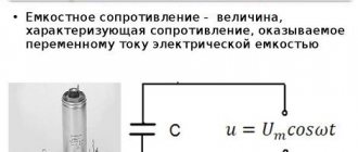
Circuit section with capacitive element
A capacitive or C-element is usually called such an idealized equivalent circuit element, which, in terms of energy, is capable only of converting the electrical energy of the source and accumulating it in the form of the energy of its own electric field (charge field). Under certain conditions, it is capable of performing a reverse transformation, giving all the accumulated energy without a trace to the external circuit (Fig. 11).
| iC |
| uC |
Rice. eleven.
The prototype of this idealized element is an electrical device called a capacitor and, conversely,
The C-element is an idealized model of a capacitor. Capacitors, in addition to the indicated property, have a number of properties that are not basic for them, and therefore these properties are not taken into account in the model.
From a physics course we know the relationship that connects the amount of charge accumulated by a capacitor with the voltage between its terminals
, (50)
where q
– charge on one of the capacitor plates (in absolute value), measured in coulombs (C);
uc
is the potential difference between the terminals of the capacitor, measured in volts (V).
Parameter C
– quantitatively characterizes the ability of a capacitive element to store electrical energy, i.e., accumulate charges. This parameter is called electrical capacitance and is measured in farads (F).
It is also known that the electric current through a capacitor has a different physical nature than conduction current. However, the current through a capacitor (current through the -element) can be quantitatively defined as the rate of change of charges concentrated on its plates
. (51)
Substituting (50) into (51), we obtain, taking into account that C
-linear element:
. (52)
Relationship (52), as well as (40), show that the instantaneous values of voltage and current on L
-element, as well as on
the C
-element, are not related by Ohm’s law.
According to the definition of C
- the element does not irreversibly consume electrical energy.
However, for it, as well as for the L
-element, one can introduce the concept of instantaneous power
p
. It is understood as the rate of conversion of the energy entering the -element into the energy of its own field of charges and vice versa:
.
from here we get
or
. (53)
Relation (53) determines the energy of the own field C-
element accumulated by the considered moment of time
t
1. Note that (53) also clearly defines the parameter
C
as a quantitative characteristic of
the C
-element, showing its ability to accumulate electrical energy: the greater
C
W
, other things being equal .
Let to the chain with C
- the element applies a sinusoidal voltage (Fig. 11)
According to (52), we determine the current flowing through this element
. (54)
With a sinusoidal voltage, the current of the capacitive element is also sinusoidal; voltage and current change at the same frequency; the current leads the voltage in phase by a quarter of the period ψ i
= ψ
u
+ 90 º;
phase angle φ = ψ u
– ψ
i
= – 90º.
From (49) we obtain Ohm’s law for amplitude
(55)
or effective values of voltage and current
. (56)
The quantity has the dimension Ohm, is called the capacitance of the element and is designated
.
In this case, (56) can be written as follows
(57)
Let us define the entry of Ohm's law in complex form. To do this, let us move from and as sinusoidal functions of time to complexes of effective values of voltage and current that uniquely represent them
.
Let's take the formal relation
. (58)
Taking into account (56) and (19), we finally obtain
or . (59)
This is Ohm's law in complexes of effective values of voltage and current.
Value jxс
is called the complex resistance of the capacitive element.
It is conventionally measured in Ohms and is a negative imaginary number, the modulus of which is equal to xc
.
The vector diagram corresponding to relation (59) is shown in Fig. 12. It shows that the vector is 90º ahead of the vector.
| +j |
| ψ i =ψ u +90º |
| +1 |
Rice. 12.
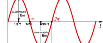
Wave diagram of current and voltage in the section with C
-element is shown in Fig. 13.
| ψi _ |
| π/2 |
| u , i |
| ωt _ |
| ωt _ |
| i ( t ) |
| u ( t ) |
Rice. 13
Let us consider the energy processes occurring in a chain with C
-element. Instantaneous power on a capacitive element
. (59)
Graph p(t)
is shown in Fig. 13.
It can be seen that the instantaneous power in a circuit with a C
-element oscillates with a frequency of 2ω and an amplitude of
U I
around the zero position. Consequently, no work is performed in this circuit and the energy of the power source is not irretrievably consumed. At the same time, a periodic exchange of energy occurs between the source and the element. Let's look at this process.
During the 1st quarter of the fundamental frequency period (time interval between points 1 and 2 in Fig. 13) U
> 0 and
i
> 0 therefore,
p
> 0 i.e.
the C
-element operates in energy consumption mode.
The energy consumed is stored in the electrostatic field the C
-element.
During the 2nd quarter of the period (the time interval between points (2 and 3) u
> 0, and
i
< 0, i.e.,
the C
-element operates in source mode. The reverse process of converting the stored energy by
the C
-element occurs, which is given to the power source.Then the process is repeated at a negative voltage.
The intensity of energy exchange is usually characterized by the highest value of the energy conversion rate, i.e., the amplitude value of instantaneous power. As follows from (59)
.
Taking (57) into account, we obtain
(60)
This quantity is called reactive power C
-element. The unit of measurement for this power is VAR.
The considered models of elementary circuit sections allow us to consider the behavior of more complex sections of electrical circuits. The simplest are models of sections with serial or parallel connection of the considered elementary models.
6. Analysis of a section of the circuit with a serial connection and - elements
Using the elements considered, you can depict a linear equivalent circuit of any electrical device. For example, an inductor at a sufficiently low frequency of sinusoidal current can be represented by the following equivalent circuit.
Rice. 14.
Suppose we know the voltage at the terminals of the inductor
.
(Let us put ψ u
=0), as well as resistance
Rk
and inductance
Lk
. It is necessary to determine the remaining parameters of its operating mode. According to Kirchhoff’s second law, for a given circuit we can write the equation for instantaneous voltage values:
(61)
or
. (62)
From relation (62) it is clear that to determine i
(
t
) it is necessary to solve the differential equation. The analysis can be simplified by moving to a symbolic method for calculating such a section of the circuit. In complex form, equation (61) will have the form
. (63)
According to (33) and (47), this equation can be written
. (64)
Since the elements in the circuit are connected in series, the same current flows through them. Then
. (65)
Equation (61) relates the total voltage applied to this circuit to the current flowing in it. That is, (65) is Ohm’s law for a given chain in complex form. Size:
(66)
is measured (conventionally) in Ohms and is called the total complex resistance of a section of this circuit. This quantity can be interpreted as vectors on the complex plane.
| +j |
| +1 |
| φ |
Rice. 15.
Real part of complex resistance z
is called the active resistance of the circuit. Its imaginary part:
is called the complex resistance modulus of the element. Triangle represented by z
and its components in Fig. 15 is called
the resistance triangle . Relationship (66) determines the algebraic form of representation of the complex z
.
In calculations, the exponential form of representation z
, (67)
where is called the module of the total complex resistance or the total resistance of a circuit section, measured in Ohms; is called the argument of the complex or phase of the total complex resistance, measured in angular degrees or radians. For the sides of the triangle (Fig. 15) the following relations are valid:
.
Taking (63) into account, we can determine the vector from (65):
(68)
xL
> 0 for linear elements. Then φ > 0 and from (68) it is clear that the current vector in such a circuit lags behind the vector by an angle 0<φ<90º. Having determined the vector from (68), you can determine the voltage drop on each element using the previously established formulas of Ohm’s law for these elements
; (69)
. (70)
Let's build a vector diagram (Fig. 16). The construction, as mentioned earlier, begins by selecting the current scale mi
(A/cm) and voltage
mu
(V/cm).
Let's determine the vector of the given voltage. Its modulus, phase ψ u
= 0, i.e. the vector is located along the axis of real numbers (
+
1).
We lay off from point 0 in the positive direction of the axis +
1 segment of length
U/mu
(cm) and mark its end with an arrow. The vector is built.
| N |
| +1 |
| +90º |
| M |
| K |
| +j |
Rice. 16.
Next, we construct the current vector. This vector was found to lag behind the vector by an angle φ. Moreover, 0<φ<90º. Therefore, in the fourth quarter of the coordinate plane we draw a ray 0M at an angle φ to the + 1 . On this ray from point 0 we plot a segment (cm). We mark its end with an arrow. The vector is built. We are building a vector. As was established earlier, the current through R
- the element and the voltage drop across it are in phase.
This is confirmed by relations (68) and (69). For a vector diagram, this means that the vectors coincide in direction. Therefore, on the same ray 0M from point 0 we lay off a segment equal to (cm), mark its end with an arrow. The vector is built. Finally, we build the vector. It was previously established that the voltage drop across the L
-element leads the current through this element in phase by 90º.
This is confirmed by relations (68) and (70). For a vector diagram, this input means that the vector must be perpendicular to the vector and directed towards the +
1 axis (since the phase difference between and is +90º, and the positive direction when rotating vectors in electrical engineering is taken to be counterclockwise).
From the end of the vector (point K in Fig. 16) we restore the perpendicular to the ray 0M in the direction of the +
1 axis. On the perpendicular KN from point K we lay a segment of length equal to (cm). We mark the end of this segment with an arrow. The vector is built. In the case of correct construction of all vectors on this diagram, the end of the vector coincides with the end of the vector. That is, the sum of the vectors and is equal to the vector, which is a geometric interpretation of Kirchhoff’s 2nd law for this chain (63).
The considered vectors , , form a right triangle, called a stress triangle. The following relations apply to the sides of this triangle:
. (71)
In conclusion, let us analyze the energy processes occurring in this chain. As was established, the intensity of energy processes occurring in the section of the chain with R
-element can be characterized by active power:
, (72)
and the intensity of the processes occurring in the section of the chain with L
-element – reactive power:
. (73)
R is included in this circuit
-element, then part of the energy of the power source will be irreversibly consumed by
the R
-element.
At the same time, due to the presence of L
element in this circuit, there will be a continuous exchange (with a frequency of 2ω) of energy (energy circulation) between the magnetic field
the L
element and the power source. To characterize the general energy regime of the circuit, the concept of total power is introduced.
Let's determine its value. From (71) and (72) we can write
(74)
(75)
Let us square (70) and (71) and add the results obtained
(76)
or
,(77)
where S
- the total power of this section of the circuit, measured in volt-amperes (VA).
We can write the relationship between total power and its components in complex form. To do this, multiply each side of the resistance triangle (Fig. 15) by . The newly formed right triangle (Fig. 17) determines the total power with its hypotenuse, and the active and reactive power with its legs. This triangle is called the power triangle. Its sides are related by the relation:
. (78)
S
– the total integrated power of a given section of the circuit. Its module
.
| +j |
| +1 |
Rice. 17.
Total power and its components are measured in units of power of the same scale. However, in order to emphasize the different physical nature of the energy processes, the intensity of which they estimate, these units of measurement are called differently:
The triangles of resistance (Fig. 15), voltage (Fig. 16) and power (Fig. 17) are similar. From this, in particular, it follows that
.(79)
We let students independently carry out a similar analysis for a section of a circuit containing a series connection R
and C-elements.
Parallel connection
When the conditional outputs of the parts have a common contact at one point (node) of the circuit, and the conditional inputs are also combined at the second, they speak of a parallel connection. A node in the drawing is indicated by a graphic dot. This is the place where branching circuits occur in circuits. This option for connecting resistors ensures the same voltage drop U for all parallel elements. The current in this position will be equal to the sum of the currents flowing through each component.
n are included in a parallel connection , the potential difference, current and total resistance will have the following expressions:
- total current: I = I1 + I2 + … + In;
- total voltage: U = U1 = U2 = … = Un;
- Rtot. = Req. = U/I1 + U/I2 + …+ U/In) = 1/R1 + 1/R2 +…+ 1/Rn.
The quantity inversely proportional to resistance 1/R is called conductivity.
If n resistances of equal nominal value are connected in parallel, then Req. = (R*R)/n*R = R/n. The formula is also suitable for the inductive reactance of wire coils and the capacitive reactance of capacitors.
Calculation for mixed connection of devices
It is simply impossible to calculate the resistance of a circuit when it is branched and filled with different types of resistive connections. The solution to the problem is complicated by the many areas where parts are connected to each other in different combinations. In such circumstances, it is desirable to perform a series of transformations, achieving simplification of the circuit by introducing individual equivalent elements. In this case, suitable circuits for serial and parallel connections are identified.
For example, having found a certain number of serial connections of resistors, replace them with one equivalent component. Having determined the elements connected in series, they also draw an equivalent instead. The search for such simple connections is beginning again.
The method is called the "coagulation method". The circuit is simplified until there is only one Req left in it.
Important! The method of equivalent transformations is used when the power supply to the section of the circuit under consideration is carried out from a single source of electric current, as well as when determining Req. in a closed loop with one EMF.
This relative method of determining Req is also used to study the dependence of currents in a certain circuit on the load R value. This is the equivalent generator method, in which a complex two-terminal network, which is active, is represented as an equivalent generator. In this case, it is believed that its EMF corresponds to Uх.х. (idle circuit) on the terminals, R internal corresponds to R input of the passive two-terminal network on the same terminals. For this determination, the current sources are disconnected and the EMF channel is short-circuited.
Parallel connection of circuit elements at alternating voltage
Now consider the parallel connection of circuit elements (resistance, inductance and capacitance) and the passage of alternating current through them.
Parallel connection of circuit elements.
Let us apply an alternating voltage U to the input of such a circuit, then the electric current in circuit I, in accordance with Kirchhoff’s first law, will be equal to the algebraic sum of the currents passing through the elements of the circuit
IR, IL, IC – currents in the circuit elements, resistance R, inductance L and capacitance C, respectively,
Um – amplitude value of alternating current.
A graphical representation of voltages and currents in parallel connected circuit elements is presented below
Voltage and currents in parallel connection.
Similar to Kirchhoff's second law, for the first law there is also a trigonometric form of notation that corresponds to the resulting expression. Let's perform another transformation of this expression
where g is active conductivity, b is reactive conductivity.
As can be seen from the formula, reactive conductivity can be positive b > 0, then it is inductive in nature, or it can be negative b < 0, then reactive conductivity is capacitive in nature. And active conductivity can only be positive.
A special case is the reactive conductance equal to zero, that is, in this case the conductivity of the inductance and capacitance are the same
This case is called current resonance , in this case the total conductivity will be determined only by active conductivity, and the phase shift between voltage and current in the circuit will be zero.
Let's determine the relationship between voltage and current in a parallel circuit
where y is admittance,
ψ – phase difference between voltage and current in the circuit.
Then the relationship between voltage and current in a circuit with elements connected in parallel will have the form
where Um is the amplitude value of the alternating voltage,
Im – amplitude value of alternating current,
y is the total conductivity of the circuit.
Physical formulas and calculation examples
Formulas for the equivalent resistances of a circuit consisting of a pair of resistors R 1 and R 2 can be divided into a certain series:
- parallel connection is determined by the formula Req. = (R1*R2)/R1+R2;
- sequential inclusion is calculated by determining its sum Req. = R1+R2.
The mixed connection of resistive elements does not have a specific formula. In order not to get confused during lengthy transformations, it is permissible to use a special program from the Internet. This is an “online calculator” service. It will help you understand complex connection diagrams, be it a triangle, square, pentagon or other schematic figure formed by resistive elements.
You can understand how all formulas and methods work using a specific problem. The first picture shown is a mixed electrical circuit. It includes 10 resistors. The elements are presented in the following denominations:
- R1 = 1 Ohm;
- R2 = 2 Ohm;
- R3 = 3 Ohm;
- R4 = 6 Ohm;
- R5 = 9 Ohm;
- R6 = 18 Ohm;
- R7 = 2Ohm;
- R8 = 2Ohm;
- R9 = 8 Ohm;
- R10 = 4 Ohm.
Voltage applied to the circuit:
It is required to calculate the currents on all resistive elements.
Ohm's law is used for calculations:
I = U/R, substituting the equivalent resistance for R.
Attention! To solve this problem, the total (equivalent) R is first calculated, after which the current in the circuit and the voltage on each resistive component are calculated.
By calculating Req., the given chain is divided into links containing parallel and serial connections. Calculations are made for each such link, and then for the entire chain.
The figure above shows a mixed resistance connection. It can be divided into three sections:
- AB – a section with two parallel branches;
- BC – a segment containing a sequential conjugation;
- CD is a section of a circuit with an arrangement of three parallel chains.
Resistances R2 and R3, forming the lower branch of segment AB, are connected in series, which is taken into account in the calculation.
If you look at section CD, you can note the mixed inclusion of resistive elements.
The beginning of the calculations is to determine the equivalent resistances for these mixed fragments. Do this in the following order:
- Req.2.3 = R2+R3=2 + 3 = 5 Ohm;
- Req.7.8 = (R7*R8)/R7 + R8 = (2*2)/2 + 2 = 1 Ohm;
- Reeq.7,8,9 = Reeq.7.8 + R9 = 1 + 8 = 9 Ohm.
Knowing the values of the obtained equivalents, the original circuit is simplified. It will look like the one shown in the figure below.
Next, you can determine Req. for sections AB , BC , CD , according to the formulas:
- Req.AB = (R1*Req. 2.3)/R1 + Reeq. 2.3 = (1*5)/1 + 5 = 0.83 Ohm;
- Req.BC = R4 + R5 = 6 + 9 = 15 Ohm;
- 1/Req.CD = 1/R6 + 1/Req.7,8.9 + 1/R10 = 1/18 + 1/9 + 1/4 = 0.05 + 0.11 + 0.25 = 0, 41 Ohm.
As a result of the calculations performed, an equivalent circuit is obtained, which includes three Req. resistance. It looks like the one shown in the figure below.
Now you can determine the equivalent resistance of the entire original circuit by adding the equivalent values of all three sections:
Req. = Req.AB + Req.BC + Req.CD = 0.83 + 15 + 0.41 = 56.83 Ohm.
Next, using Ohm's law, find the current in the last serial section:
I = U/ Req. = 24/56.83 = 0.42 A.
Knowing the current strength, you can find what the voltage drop is in the considered sections AB, BC, CD. This is done as follows:
- UAB = I* Req.AB= 0.42*0.83 = 0.35 V;
- UBC = I* Reeq.BC = 0.42*15 = 6.3V;
- UCD = I* Req.CD = 0.42*0.41 = 0.17 V.
The next step is to determine the currents on parallel segments AB and CD :
- I1 = UAB/R1 = 0.35/1 = 0.35 A;
- I2 = UAB/Req.2.3 = 0.35/5 = 0.07 A;
- I3 = UCD/R6 = 0.17/18 = 0.009 A;
- I6 = UCD/Req.7,8,9= 0.17/9 = 0.02 A;
- I7 = UCD/R10 = 0.17/4 = 0.04 A.
Next, to find the values of the currents passing through R7 and R8, you need to calculate the voltage across these two resistors. First find the voltage drop across R9.
U9 = R9*I6 = 8*0.02 = 0.16 V.
Now the voltage falling on Req. 7.8 will be the difference between U CD and U9.
U7.8 = UCD – U9= 0.17 – 0.16 = 1 V.
After this, you can already find out the value of the currents moving through resistors R 7 and R 8, using the formulas:
- I4 = U7.8/R7 = 1/2 = 0.5 A;
- I5 = U7.8/R8 = 1/2 = 0.5 A.
Worth noticing! The current flowing through R4 and R5 is equal in value to the current in the segment that does not have a branch.
When calculating circuits and solving problems of finding the values of electrical parameters, it is necessary to use equivalent resistances. With the help of such a replacement, complex structures are transformed into elementary circuits, which are reduced to parallel and series connections of resistive elements.
Electromagnetic processes occurring in electrical devices are usually quite complex. However, in many cases, their main characteristics can be described using such integral concepts as: voltage, current, electromotive force (EMF). With this approach, a set of electrical devices, consisting of appropriately connected sources and receivers of electrical energy, intended for the generation, transmission, distribution and conversion of electrical energy and (or) information, is considered as an electrical circuit
.
An electrical circuit consists of individual parts (objects) that perform specific functions and are called circuit elements
.
The main elements of the circuit are sources and receivers of electrical energy (signals). Electrical devices that produce electrical energy are called generators
or
sources of electrical energy
, and devices that consume it are called
receivers
(consumers) of electrical energy.
Each element of the circuit can have a certain number of terminals ( poles
), with the help of which it is connected to other elements.
There are two
and
multi-pole
elements. Double-terminal circuits have two terminals. These include energy sources (with the exception of controlled and multiphase), resistors, inductors, capacitors. Multi-pole elements are, for example, triodes, transformers, amplifiers, etc.
All elements of the electrical circuit can be divided into active
and
passive
.
An element that contains a source of electrical energy in its structure is called active. Passive elements include elements in which energy is dissipated (resistors) or accumulated (inductors and capacitors). The main characteristics of circuit elements include their current-voltage, Weber-ampere and coulomb-voltage characteristics, described by differential and/or algebraic equations. If the elements are described by linear differential or algebraic equations, then they are called linear
, otherwise they belong to the class of
nonlinear
.
Strictly speaking, all elements are nonlinear. The possibility of considering them as linear, which significantly simplifies the mathematical description and analysis of processes, is determined by the boundaries of change in the variables that characterize them and their frequencies. The coefficients connecting the variables, their derivatives and integrals in these equations are called the parameters
of the element.
If the parameters of an element are not functions of the spatial coordinates that determine its geometric dimensions, then it is called an element with lumped parameters
.
If an element is described by equations that include spatial variables, then it belongs to the class of elements with distributed parameters
. A classic example of the latter is the power transmission line (long line).
Circuits containing only linear elements are called linear. The presence of at least one nonlinear element in a circuit classifies it as nonlinear.
Let's consider the passive elements of the circuit, their main characteristics and parameters.
1. Resistive element (resistor)
A conventional graphical representation of the resistor is shown in Fig. 1, a. A resistor is a passive element characterized by resistive resistance. The latter is determined by the geometric dimensions of the body and the properties of the material: resistivity r (Ohm´ m) or the inverse value - conductivity (S/m).
In the simplest case of a conductor with length and cross-section S, its resistance is determined by the expression
.
In general, determining the resistance involves calculating the field in the conducting medium separating the two electrodes.
The main characteristic of a resistive element is the dependence (or), called the current-voltage characteristic (volt-ampere characteristic). If the dependence is a straight line passing through the origin of coordinates (see Fig. 1, b), then the resistor is called linear and is described by the relation
or
,
where is conductivity. In this case R=const.
A nonlinear resistive element, the current-voltage characteristic of which is nonlinear (Fig. 1, b), as will be shown in the block of lectures devoted to nonlinear circuits, is characterized by several parameters. In particular, the inertia-free resistor is matched with static and differential resistance.
2. Inductive element (inductor)
A conventional graphical representation of an inductor is shown in Fig. 2, a. A coil is a passive element characterized by inductance. To calculate the inductance of a coil, it is necessary to calculate the magnetic field created by it.
Inductance is determined by the ratio of the flux linkage to the current flowing through the turns of the coil,
.
In turn, the flux linkage is equal to the sum of the products of the flux passing through the turns and the number of these turns, where .
The main characteristic of an inductor is a relationship called the Weber-amp characteristic. For linear inductors, the dependence is a straight line passing through the origin of coordinates (see Fig. 2, b); wherein
.
The nonlinear properties of the inductor (see the curve in Fig. 2b) are determined by the presence of a core made of ferromagnetic material, for which the dependence of magnetic induction on field strength is nonlinear. Without taking into account the phenomenon of magnetic hysteresis, the nonlinear coil is characterized by static and differential inductance.
3. Capacitive element (capacitor)
A conventional graphical representation of the capacitor is shown in Fig. 3, a.
A capacitor is a passive element characterized by capacitance. To calculate the latter, it is necessary to calculate the electric field in the capacitor. Capacitance is determined by the ratio of the charge q on the capacitor plates to the voltage u between them
and depends on the geometry of the plates and the properties of the dielectric located between them. Most dielectrics used in practice are linear, i.e. they have a relative dielectric constant =const. In this case, the dependence is a straight line passing through the origin of coordinates (see Fig. 3,b) and
.
For nonlinear dielectrics (ferroelectrics), the dielectric constant is a function of the field strength, which causes the nonlinearity of the dependence (Fig. 3b). In this case, without taking into account the phenomenon of electrical hysteresis, the nonlinear capacitor is characterized by static and differential capacitances.
Equivalent circuits for electrical energy sources
The properties of an electrical energy source are described by the current-voltage characteristic, called the external characteristic of the source.
Further in this section, to simplify the analysis and mathematical description, constant voltage (current) sources will be considered. However, all the resulting laws, concepts and equivalent circuits fully apply to alternating current sources. The current-voltage characteristic of the source can be determined experimentally based on the diagram presented in Fig. 4, a. Here, the voltmeter V measures the voltage at terminals 1-2 of the source I, and the ammeter A measures the current I consumed from it, the value of which can be changed using a variable load resistor (rheostat) RN.
In the general case, the source’s current-voltage characteristic is nonlinear (curve 1 in Fig. 4b). It has two characteristic points that correspond to:
a – idle mode
;
b – short circuit mode
.
For most sources, short circuit mode (sometimes no-load) is unacceptable. Source currents and voltages can usually vary within certain limits, limited above by values corresponding to the rated mode
(a mode in which the manufacturer guarantees the best conditions for its operation in terms of efficiency and long service life). This makes it possible, in a number of cases, to simplify calculations, to approximate the nonlinear current-voltage characteristic in the working section mn (see Fig. 4, b) of a straight line, the position of which is determined by the working intervals of voltage and current changes. It should be noted that many sources (voltaic cells, batteries) have linear current-voltage characteristics.
Line 2 in Fig. 4b is described by the linear equation
| , | (1) |
where is the voltage at the source terminals with the load off (open key K in the circuit in Fig. 4a); — internal source resistance
.
Equation (1) allows you to create a sequential equivalent circuit
source (see Fig. 5,a).
In this diagram, the symbol E indicates an element called an ideal emf source
. The voltage at the terminals of this element does not depend on the source current; therefore, the current-voltage characteristic in Fig. 1 corresponds to it. 5 B. Based on (1) from such a source. Note that the directions of the EMF and voltage at the source terminals are opposite.
If the current-voltage characteristic of the source is linear, then to determine the parameters of its equivalent circuit
it is necessary to measure voltage and current for any two modes of its operation.
There is also a parallel source equivalent circuit. To describe it, we divide the left and right sides of relation (1) by . As a result we get
or
| , | (2) |
Where ; — internal conductivity of the source
.
Equation (2) corresponds to the source equivalent circuit in Fig. 6, a.
In this diagram, the symbol J denotes an element called an ideal current source
. The current in the branch with this element is equal to and does not depend on the voltage at the source terminals; therefore, the current-voltage characteristic in Fig. 1 corresponds to it. 6, b. On this basis, taking into account (2) from such a source, i.e. its internal resistance.
Note that in the design plan, if the condition is met, the sequential and parallel source equivalent circuits are equivalent. However, in terms of energy, they are different, since in idling mode for a series equivalent circuit the power is zero, but for a parallel circuit it is not.
the coordinated mode is important
operation at which the maximum power is consumed by the load RN from the source
| , | (3) |
The condition for this regime
| , | (4) |
In conclusion, we note that in accordance with the current-voltage characteristic in Fig. 5,b and 6,b ideal sources of EMF and current are sources of infinitely large power.
Literature
- Fundamentals
of circuit theory: Textbook. for universities / G.V. Zeveke, P.A. Ionkin, A.V. Netushil, S.V. Strakhov. –5th ed., revised. –M.: Energoatomizdat, 1989. -528 p. - Bessonov
L.A. Theoretical foundations of electrical engineering: Electric circuits. Textbook for students of electrical engineering, energy and instrument engineering specialties of universities. –7th ed., revised. and additional –M.: Higher. school, 1978. –528 p. - Theoretical
foundations of electrical engineering. Textbook for universities. In three volumes. Under general. ed. K.M.Polivanova. T.1. K.M.Polivanov. Linear electrical circuits with lumped constants. –M.: Energy, 1972. –240 p. - Kaplyansky A.E.
and others. Theoretical foundations of electrical engineering. Ed. 2nd. Textbook a manual for electrical engineering and energy majors at universities. –M.: Higher. school, 1972. –448 p.
Test questions and tasks
- Can the external characteristics of the source pass through the origin?
- Which mode (idle or short circuit) is an emergency for the current source?
- What are the equivalence and differences between series and parallel source equivalent circuits?
- Determine the inductance L and the energy of the magnetic field WM of the coil, if at a current in it I = 20 A, the flux linkage is y = 2 Wb.
Answer: L=0.1 H; WМ=40 J. - Determine the capacitance C and the energy of the electric field WE of the capacitor, if at a voltage on its plates U = 400 V, the charge of the capacitor is q = 0.2´ 10-3 C.
Answer: C=0.5 µF; WE=0.04 J. - For a DC generator, with a load current I1=50A, the voltage at the terminals is U1=210V, and the inflow equal to I2=100A, it drops to U2=190V.
- Determine the parameters of the source series equivalent circuit and the short circuit current.
Answer: - Derive relationships (3) and (4) and determine the maximum power supplied to the load according to the conditions of the previous problem.
Answer: