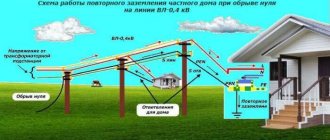
Not all, but many electricians can make mistakes when it comes to grounding. And what can we say about ordinary people who are simply interested in electrical engineering. The topic of grounding is interesting, but poorly covered. As a rule, it is limited to excerpts from the PUE and some obvious things. We will try to dig deeper, and in this publication we will analyze in detail two interesting definitions from the PUE (1.7.20 and 1.7.21):
- Zero potential zone (relative ground) is a part of the earth located outside the zone of influence of any ground electrode, the electric potential of which is assumed to be zero.
- The spreading zone (local ground) is the ground zone between the ground electrode and the zero potential zone. The term land used in the chapter (we are talking about the chapter of the PUE) should be understood as the land in the spreading zone.
Spreading phenomenon
In a 3-phase supply network operating according to a circuit with a so-called “isolated” neutral, a phase-to-ground fault can be judged by the readings of an indicator device (voltmeter) connected to it. To organize such measurements, its control probes are connected to the contacts of the secondary winding of an NTMI type instrument transformer, capable of withstanding long-term overvoltages.
When a conductor is directly or directly short-circuited to ground, the winding of the instrument transformer is short-circuited, and the readings of the corresponding voltmeter will be zero.
At the same time, the total magnetic flux (induction) in the other two NTMI windings will increase by √3 times, and the corresponding voltmeters measure the linear voltage instead of the phase voltage.
In the case of practical measurement of capacitive ground fault current, the “selection” method is used. Its essence lies in deliberate displacement of the neutral (supplying alternating voltage to the neutral) and measuring the currents arising from this.
The method is applied only in dry weather to networks of no more than 10 kV. Those workers who have received permission can carry out measurements of ground fault current.
The calculated earth fault current is determined as the geometric sum of its capacitive components in all working conductors according to the following formula:
As the length of the network increases, its capacity naturally increases and, according to the formula, the emergency leakage current increases. At the same time, in accordance with the requirements of the PUE, the current value in the circuit should not exceed the following values:
To fulfill this requirement, compensation of capacitive ground fault current must be forcibly organized in 3-phase supply circuits.
Rules for moving in the step voltage zone
In industrial conditions, to move in an area of high risk of step voltage, one should move in galoshes or dielectric boots. If you accidentally end up in a dangerous place, you need to slow down. Reduce the distance between your legs as much as possible while walking - put your toe to your heel, imitating a goose step. It is prohibited to approach bare wires at a distance of less than 8 meters; such actions are permitted if you have protective equipment.
When accidents occur on power lines, specially trained electricians are involved in eliminating the consequences. Relay protection disconnects the section of the electrical line at the location of the fault. After fixing the problem, specialists inspect the area for loose cables. High danger occurs at the junction of damaged cables (wires) and trees. The trunk is a conductor of electricity, creating a high level of danger for people and animals.
The voltage class and soil resistivity determine the step voltage. The range of action increases with increasing humidity due to an increase in the area of current spreading.
Consequences of a short circuit
Current spreading in networks with an insulated neutral is possible only through a wire in direct contact with the ground. The closest example of such a situation is an artificial ground electrode.
Current drain
An emergency phase-to-ground fault leads to the same effect, resulting in a sharp decrease in the potential of the conductor relative to the ground.
In this situation, such a wire formally turns into a single ground electrode.
The voltage at the point of contact is reduced to a value corresponding to the product of the current flowing through it and the value of the soil's resistance to its spreading.
This phenomenon is very useful in terms of reducing the danger of accidental damage to the line. At the same time, lowering the phase potential leads to a number of undesirable consequences.
One of the negative consequences is the effect of potential distribution over the earth's surface near the contact zone. As a result, potentials of different magnitudes appear at points at different distances from the grounding structure, creating voltage drops that are dangerous for people in this area.
This circumstance was the reason for the introduction of such an indicator as “step voltage”, determined by the potential difference between his feet when moving within the boundaries of the danger zone.
Due to the fact that the potential decreases exponentially with distance from the contact point, the maximum step voltage is observed close to it. The minimum of this value appears in areas sufficiently remote from the epicenter of the accident.
The nature of the distribution of ground fault current, the magnitude of the spreading resistance and the distribution of potentials in a dangerous area - all these indicators depend on the geometric parameters of the formed connection. They are also significantly influenced by the condition of the soil at the time of the accident (high humidity, dryness or other factors).
Arc occurrence
Another consequence of a phase conductor being shorted to ground is the formation of an electric arc, during the combustion of which a large amount of heat is released and air ionization is observed. This creates conditions conducive to the appearance of a short circuit in linear interphase circuits.
The intermittent nature of the arc formed during a ground fault leads to the appearance of significant overvoltages of up to 3.2 Uph. In order to reduce the amplitude of capacitive currents, increase the voltage recovery time in the emergency phase, as well as limit overvoltages during subsequent arc ignitions, a special arc suppression reactor.
What is step voltage
Step voltage is the potential difference (voltage) across a section in a current circuit.
The step voltage indicator depends on the current strength and soil resistivity. It represents the distance (potential difference) between two human legs. The magnitude of the step voltage is used to create grounding and grounding, and to measure danger in accident sites. The value is affected by the shape of the voltage curve. Near a fallen live wire, an area of electricity dissipation appears. At a distance of 20 meters to the place where the wire falls, the voltage may not be felt, and the current density becomes minimal.
Life-threatening step voltages are observed where high-power electrical wires fall onto bare ground. It is prohibited to approach this object within a distance of less than 8 meters. The threat is also present at a distance of one meter from the ground electrode (metal pipe structures, reinforced fence). A person runs the risk of touching metal structures (natural grounding conductor) when standing in a place where step voltage is spreading. The danger lies in damage to the nervous system - convulsions occur and a person falls to the ground.
The action of the step voltage stops, but a new path of electricity appears inside the body. The current flows from the arms to the legs, resulting in a real threat of death. If you find yourself in such a situation, a person should walk out of the danger zone in a goose-step. The minimum distance between the legs is the key to safety and a safe exit.
The threat disappears after 20 meters from a high potential voltage source. It is strictly forbidden to jump out of the area of high potentials. If a limb falls, the level of step voltage will increase, after which the person will die.
Compensatory protection measures
In accordance with the provisions of the PUE, under normal network operating conditions, special measures must be taken to protect against possible ground faults.
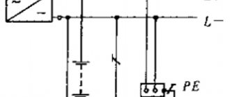
To limit capacitive currents, a special arc suppression reactor is introduced into the transformer neutral (see Figure 1, b). With its help, it is possible to reduce (compensate) the current of a single-phase ground fault that occurs immediately after an accident.
It has been practically established that in the presence of a compensator, overhead and cable lines can operate in critical emergency mode for quite a long time and here’s why.
As soon as the inductive current Ip flowing in the reactor is compared in magnitude with the out-of-phase capacitive component Ic, a compensation effect is observed, in which Iр + Iс = 0 (the phenomenon of current resonance).
Reactors with inductive impedance are quite simply configured to operate with a variable value of the compensation flow and can be operated in under- and overcompensation modes.
The use of an arc suppression reactor has a certain effect on the distribution of potentials in linear wires and in the neutral. In the latter, a bias voltage Ucm appears, caused by asymmetry in the circuit and applied to the reactor terminals.
In the resonant mode, such a mismatch leads to a distortion of the normal pattern of potential distribution even in the absence of a single-phase fault (SFC).
Artificial prevention of resonance phenomena can be achieved by deliberately mismatching the corresponding circuits, as a result of which it is possible to reduce Ucm and equalize the readings of control devices.
Additional note. It is allowed to vary the value of compensation currents within limits in which the mismatch formed in the event of an accident would not lead to the appearance of Ucm more than 0.7 Uph.
Maximum step voltage radius
8 meters is the maximum damage radius (above 1000 V). A distance of 5 meters is characterized by a power below 1000 V. When rescuing a victim, you should act judiciously. Pre-wrap your hands with a dry cloth, move in small steps, and slowly pull the person away from the danger zone.
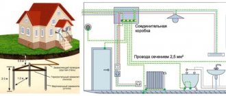
The threat of getting into the step voltage area also exists in domestic conditions. You can get into this situation by touching the exposed wire of a faulty device. In this case, an electrical circuit is formed that is dangerous to life. To eliminate the threat, a residual current device is installed in the panel. An alternative option is to develop a grounding and potential monitoring system.
Spreading of current in the ground during a short circuit
Spreading of current in the ground during a short circuit
When a ground fault occurs, an emergency current IЗ begins to flow through the ground, which radically changes the state of electrical installations from the point of view of its safety. In this case, voltages appear between the housings of electrical equipment and the ground, as well as between individual points on the earth’s surface where people may be.
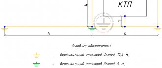
Rice. 11.2. Spreading of current in the ground through a hemispherical ground electrode
When current flows in the elementary section dx (Fig. 11.2), a voltage drop dv is created (a hemispherical ground electrode is adopted).
| dv = I3 * dr; | dr = | *dl | = | *dx | ; | dv = | I3* | *dx, |
| S | 2×2 | 2×2 |
where is the soil resistivity;
S = 2x2 - section of the hemisphere.
Let us determine the potential difference between point A with coordinate X and the point where the potential, i.e. :
| Then |
This is the equation of a hyperbola (see Fig. 11.2).
The maximum voltage drop will be at the ground electrode, and more distant points of the ground, having a large cross-section, have less resistance to the current IЗ. If point A is placed on the surface of the electrode at a distance ХЗ from the center, then its potential will be equal to
= U3 = I3 * / 2X3 = I3R3,
where R3 is the resistance to current flow.
This is the voltage of the electrode relative to ground. Grounding material
- metal. It has low resistivity, so the voltage drop across the ground electrode is negligible. The body of an electrical installation grounded through this ground electrode will have the same potential if the voltage drop in the resistance of the connecting wires is neglected. From experiments it was found that at a distance of 20 meters from the ground electrode the potential is practically zero.
Step voltage Ush (V)
- there is a voltage between two points of the current circuit, located one step apart from each other, on which a person is simultaneously standing. In this case, the step length a is taken equal to 0.8 m.
where is the step coefficient.
Thus, if a person is more than 20 m away from the ground electrode, the coefficient b is practically equal to zero, the step voltage UШ = 0, i.e. with distance from the ground electrode, UШ decreases.
Touch voltage Upr(V)
there is a voltage between two points of a current circuit that are simultaneously touched by a person, or a potential difference between the arms and legs.
UPR=Р-Н,
where P, N are the potentials of the arms and legs relative to the ground.
Rice. 11.2. Diagram of touch voltage to grounded live parts
When a breakdown occurs on the housing, the ground electrode and the associated equipment elements receive a voltage relative to the ground UЗ = IЗRЗ, therefore, human hands touching the housings anywhere receive this potential:
| P = U3 = I3R3 = | I3 | . |
| 2*x3 |
The leg potential is determined by the shape of the potential curve as the current spreads and distance from the ground electrode:
| N = | I3 | , |
| 2*x |
hence,
where is the contact coefficient for hemispherical ground electrodes.
At a distance X = (practically X = 20 m), the contact voltage has the greatest value (point A, Fig. 11.2) UPR = 3, with =1. This is the most dangerous case of touch. At the lowest value of x, when a person stands directly on the ground electrode, UPR = 0; = 0. This is a safe case. For other values of x within the range of 0-20 m, Upr smoothly increases from 0 to 3, and from 0 to 1.
Analysis of danger conditions in three-phase networks
Analysis of the hazard conditions of three-phase electrical networks practically comes down to determining the amount of current flowing through a person and assessing the influence of various factors: the circuit of a person being connected to the circuit, the network voltage, the circuit of the network itself, the mode of its neutral, the isolation of live parts from the ground, etc. .
In a three-phase three-wire network with an isolated neutral, the current strength (A) passing through the human body when touching one of the phases of the network during its normal operation (Fig. 11.3) is determined by the following expression in complex form:
ICh = UФ/RF + Z/3,
where Z is the impedance complex of one phase relative to ground.
| 1000 B |
| Rice. 11.3. Network diagram with isolated neutral |
If the capacitance of the wires relative to the ground is small, i.e. C = 0, and the phase insulation resistance relative to the ground is equal to R1 = R2 = R3 = R, then the current through a person will be equal to
| I4 = | 3UФ | . |
| 3RХ + R |
With good insulation (R = 0.5 MOhm), the current is low and such contact is not dangerous. Therefore, it is very important in such networks to ensure high insulation resistance and monitor its condition in order to promptly eliminate any faults that may arise. If the network has a large capacitance relative to ground (branched cable lines), then single-phase contact will be dangerous, despite the good insulation of the wires.
,
where Xc is capacitance equal to 1/s, Ohm;
c is the phase capacitance relative to ground.
In networks with an isolated neutral, it is especially dangerous to touch a healthy phase when any other phase, for example the second, is shorted to ground (Fig. 11.3). In this case, the person is switched on to full line voltage.
.
In networks with a grounded neutral, the neutral grounding resistance RЗ is very small compared to the leakage resistance R. Therefore, the current flowing through a person when touched is determined by the phase voltage of the network UФ, the resistance of the floor and shoes RPO and the neutral grounding resistance RЗ (Fig. 11.4).
ICh = UF/RCH + RPO + RЗ.
Rice. 11.4. Network diagram with grounded neutral
It follows that touching a phase of a three-phase network with a grounded neutral during its normal operation is more dangerous than touching a phase of a normally operating network with an isolated neutral.
During emergency operation, when one of the phases of the network is shorted to ground through a relatively low resistance RPC (phase 2), and a person touches one of the other two phases, the person finds himself approximately under phase voltage (Rz is small, Fig. 11.5). This is one of the advantages of networks with grounded neutral point from a safety point of view.
Rice. 11.5. Vector diagram for ground fault
When analyzing networks with voltages above 1000 V, it should be noted that these networks are long, have significant capacity and a high insulation resistance value. Therefore, in these networks, current leakage through the active insulation resistance can be neglected and only current leakage through the phase capacitance relative to ground can be taken into account. Therefore, touching these networks is dangerous regardless of the neutral mode.
In accordance with the PUE, networks with a voltage of 6-35 kV are made with an insulated neutral or with grounding of the neutral through a reactive coil in order to reduce the ground fault current.
Networks with voltages of 110 kV and higher are performed with neutral grounding.
The choice of the network diagram, and therefore the neutral mode of the current source, is made based on technological requirements and safety conditions.
According to technological requirements, at voltages up to 1000 V, preference is given to a four-wire network, since it allows the use of two operating voltages: linear and phase. According to security conditions, the choice of one of the two systems is made taking into account the conclusions obtained when considering these networks.
It is advisable to use networks with an isolated neutral provided that the insulation is maintained well and the network capacity is low. (networks of electrical laboratories, small enterprises, etc.).
Networks with a grounded neutral should be used where it is impossible to ensure good insulation of the wires (due to high humidity, aggressive environment, large capacitive currents, etc.). An example of such networks are large modern enterprises.
The choice of network circuit with voltages above 1000 V was discussed earlier.
Efficiency of methods for limiting overvoltages in networks 6
—
10 kV for phase-to-ground faults”
current spreading earth phase
In conditions of constant deterioration of the technical condition of distribution networks due to the lack of necessary funds for timely replacement and high-quality repair of damaged electrical equipment, the problem of maintaining the reliability of power supply systems for consumers of electrical energy at a sufficiently required level is becoming increasingly acute. Being the most extensive, distribution networks often operate in very difficult conditions of pollution, moisture, frequent dynamic and thermal overloads, while the average service life of most of the main electrical equipment of these networks significantly exceeds the standard service life.
All this leads to a noticeable increase in the damage to electrical equipment of networks due to various defects, including those developing under the influence of operating voltage.
The greatest danger is represented by arc overvoltages that occur in the network due to the intermittent (unstable) nature of the arc burning at the point of breakdown of the phase insulation to the ground. Thus, the main direction of measures to improve the reliability of medium voltage networks is the prevention of switching and, especially, arc overvoltages.
In the current conditions, an effective solution to the problem of significantly increasing the level of reliability of distribution networks can only be found in an integrated approach to solving this problem.
On the one hand, it is necessary to follow the path of gradual replacement of electrical equipment with worn insulation with new ones, for which most internal overvoltages will not be dangerous to such an extent, and on the other hand, it is necessary to take measures to minimize all electrical impacts on weakened insulation, creating conditions for extending the life operation of aged electrical equipment.
Improving the reliability of distribution networks can be achieved by significantly limiting internal overvoltages by optimizing the neutral grounding mode. The neutral mode of the high voltage electrical network is the most important factor determining the nature of the operation of electrical equipment, influencing the choice of insulation and the organization of relay protection. This mode determines transient electromagnetic processes and associated overvoltages, electrical safety conditions for ground faults and requirements for grounding devices of electrical installations.
The main advantage of networks with an isolated neutral is the high degree of reliability of power supply to consumers of electrical energy at relatively low costs for redundancy, since in case of single-phase ground faults (the most common type of damage), the network can remain in operation for a long time (up to four hours), sufficient to find and eliminating the damage site. However, when operating a network with an isolated neutral, single-phase ground faults are inevitably accompanied by the occurrence of overvoltages specific to this mode, the main of which include arc overvoltages. Such overvoltages exist in the form of transient processes during an intermittent arc and are dangerous for electrical equipment due to their high multiplicities and duration.
The occurrence of overvoltages during single-phase arc faults to ground occurs due to the displacement of the network neutral, which leads to an increase in voltages in healthy phases to linear ones. The high-frequency component of the transient process superimposed on the steady-state voltage value significantly increases the multiplicity of arc overvoltages. This can be seen in Fig. 1. When phase C is closed to ground, a voltage appears on the neutral U0, the increase of which in the process of repeated ignition and extinguishing of the fault current arc leads to a gradual increase (escalation) of overvoltages in the network.
Figure 1 - Short circuit of phase C to ground and extinction of the arc during the first transition through “zero” of the current of high-frequency oscillations (C=3uF, IC=10A)
Since there are currently no reliable means of protecting the electrical equipment of auxiliary networks from the consequences of single-phase ground faults, one of the successful solutions to this problem can be found by optimizing the control of the neutral mode, ensuring maximum limitation of the amplitude and duration of all possible voltage increases and reducing to a minimum thermal losses at the point of insulation breakdown.
The determination of the main factors that influence the nature of transient processes and the magnitude of overvoltages during single-phase ground faults was carried out using a mathematical model developed at the Department of Electric Power Plants of Donetsk National Technical University. It allows you to simulate a solid phase fault to ground and through an intermittent arc, with its extinction when the high-frequency component (Petersen theory) or the power frequency current component (Peters and Slepyan theory) passes through zero, as well as multiple insulation breakdown at different values of the cable network parameters, transformers, motor load and operating mode of the network neutral. Using the loop current method, a system of differential equations of the 50th order is obtained for the auxiliary replacement circuit, which is numerically integrated by the implicit Euler method, which has increased numerical stability, the general expression of which at each i-th calculation step h is as follows:
where is the vector of the required variables;
— vector of initial approximations;
— current calculation time;
— number of equations to be solved.
The resulting system of linear algebraic equations, written relative to the vector of the desired variables, is solved at each step by the Gauss method:
where A is a matrix of current coefficients of size ;
B is the column vector of initial approximations and free terms of the system of equations.
Analysis of the results obtained allows us to conclude that the presence of features in the nature of transient processes in a network with a resistively grounded neutral, where the frequency parameters of current and voltage can vary within wide limits, may be the reason why In power plants, relays RTZ-51 (RTZ-50, RT-40/0.2) under conditions of frequently repeated breakdowns, so-called pecks, do not have time to operate successfully, and can remain in this state for a long time even with high ground fault currents. Although small in magnitude, long-term overvoltages in this case can cause damage to the electrical equipment of the network. Based on the foregoing, we can conclude that resistive grounding of the neutral of the auxiliary network of power plants does not exclude the possibility of damage to electrical equipment under conditions of unstable arc burning, which is confirmed in operation.
The disadvantages of resistor grounding of the neutral of a 6 kV network should also include the low thermal resistance of a betel resistor with a value of 100-400 Ohms, since the permissible short circuit duration does not exceed 1.2 minutes. After this time, the connecting transformer, in the neutral of which the resistor is connected, must be turned off and the network is transferred to a mode with an isolated neutral with all its inherent disadvantages.
The most common method currently used to prevent emergency consequences from single-phase faults in the networks under consideration is grounding the neutral of the networks through tuned inductances (DGK), which, while maintaining the advantages of networks with an isolated neutral, are designed to improve the operating conditions of electrical equipment during single-phase ground faults. This improvement is expected due to a significant reduction in the speed of voltage recovery in the damaged phase after the arc goes out and a reduction in the current at the ground fault to the level of the active component and higher harmonics. As a result, the arc spontaneously goes out, and, consequently, the volume of destruction associated with the thermal action of the grounding arc is reduced, as well as the overvoltage ratio is reduced to a safe value, since there are ways for static charges to flow to the ground from the capacitance of the healthy phase network elements. However, to achieve such results, the degree of detuning of the coil should not exceed the limits.
When installing coils in 6-35 kV networks, the speed of voltage recovery in the sick phase after the arc goes out decreases. When finely tuning the coil to resonance, the time to restore the voltage to the nominal value is several seconds. During this time, the insulation strength at the damage site has time to recover. But this process also has negative sides, because all this time the healthy phases maintain a voltage of the order of (1.9-2.3) Uph. The relative duration of such overvoltages can lead to insulation breakdown in these phases, especially in old networks with poor insulation.
In real networks, it is impossible to tune the coil exactly to resonance, since the inductance of the coil is controlled discretely. Coil detuning v<5% is allowed. With a detuning of 5%, the recovering voltage on the damaged phase has a beating character. The voltage envelope reaches a maximum of 1.78Uph. Subsequently, the voltage envelope tends to Uph. The insulation strength can be restored at the time of maximum beating, but a voltage of 1.78Uph in the sick phase can cause a repeated breakdown of the insulation with a subsequent overvoltage ratio of 2.89Uph. When the detuning is more than 25%, the overvoltage factor is the same as in networks without installing an arc-extinguishing coil. At the same time, the multiplicity of overvoltages with overcompensation is slightly less than with undercompensation.
In the presence of asymmetry, tuning the DGK installed in the network into resonance leads to a sharp increase in the neutral bias voltage in normal operation of the network. Moreover, the asymmetry of the phase capacitances relative to the ground has a stronger effect on the magnitude of the neutral displacement than the asymmetry of the active insulation resistances.
Based on the research carried out by the Department of Electrical Plants of Donetsk National Technical University, it was proposed to eliminate the identified deficiencies caused by the displacement of the network neutral and the long-term existence of increased voltages in phase-to-ground fault modes, connecting a resistor in parallel to the DGK through a contactor. The resistor resistance is selected so that the unbalance voltage does not exceed the permissible value, and the magnitude and duration of overvoltages are minimal. In order to prevent the resistor from overheating by high currents during a stable single-phase circuit, it is turned off using a contactor with a time delay of 0.5 s when the zero-sequence voltage exceeds 20% of the nominal one.
Of all the variety of areas of work to improve the system for compensating capacitive currents to the ground, DGKs of the ZROM type with stepwise control of the coil inductance and plunger DGKs with smooth control of the inductance turned out to be acceptable for practical implementation and have become widespread. In the first case, regulation is carried out by switching branches on the working winding of the DGR. The current control step for such devices is at least 10% of the total coil current. Switching taps is done only manually when the voltage is completely removed. Consequently, in modern conditions of power shortages and the presence of an emergency shutdown schedule for electrical receivers, when using such stepwise adjustable arc extinguishing devices, the occurrence of significant compensation detunes is inevitable.
In the second case, regulation of the DGK is carried out by smoothly changing the size of the air gap between the moving parts of the magnetic circuit (plungers). Such coils have a linear magnetizing characteristic in all modes of network operation. They are operated, as a rule, in a unit with automatic compensation adjustment devices and provide a current control speed within the range of 0.25-2 A/s.
As regulators, non-search devices are used, usually home-made, based on the principle of phase-locked loop frequency control of the zero-sequence circuit and the operating voltage of the network. The regulators do not have a system for monitoring the output of the controlled object into the resonance region and do not have feedback on the degree of coil tuning. If we take into account that the accuracy of the setting largely depends on the total capacity of the entire network, long-term and random changes in the insulation state of electrical equipment, a large number of possible parametric disturbing factors, etc., which require periodic intervention of maintenance personnel in the control system, then it becomes obvious that that under operating conditions, monitoring the degree of coil tuning is significantly difficult, and high tuning accuracy is unlikely.
It is also proposed to increase the reliability of the operation of auxiliary networks of 6 kV power plants by converting all single-phase ground faults that occur in the auxiliary system into closed circuits. For this purpose, three single-pole switches with individual drive and control should be connected between the 6 kV busbars and the ground (Fig. 2).
When any type of single-phase ground fault occurs, using the damaged phase selection device (UVPS), the corresponding shunt single-phase switch (KM1-KM3) connected to the ground is automatically switched on, thereby shunting the damaged phase. The faulty phase selection device operates with a time delay of about 0.5 s, adjusted from the time of protection at the outgoing connections. The UVPF starting element is triggered when a voltage 3Uо appears on the transformer TV, exceeding a given setting, and when one of the phase voltages decreases to a given level, it sends a command to turn on the corresponding bypass switch (KM1-KM3).
Figure 2 — Schematic diagram of limiting overvoltages and converting arc faults to dead ones
Limitation of overvoltages in the auxiliary system is carried out by connecting nonlinear zinc oxide active resistances of the OPN-KS-6/47 type to the busbars. The latter provide deep limitation of overvoltages to the level of 2Uph. However, their disadvantage is low thermal resistance, since the permissible operating time is about 2 s in the mode of a single-phase ground fault in a 6 kV network. In this regard, it is proposed to connect a single-pole switch in the neutral circuit of phase arresters connected in a star (Fig. 1), through which the neutral of the arrester is connected to the ground. In this case, a blocking is performed between the bypass switches KM1-KM3 and the neutral switch of the arrester KM0, which, when any of the bypass switches is turned on, automatically turns off the neutral switch KM0 and transfers two series-connected arresters to connection to line voltage, which limits their operating time in case of a single-phase ground fault .
Suppression of overvoltages in the network from the moment the arc starts until the damaged phase is shunted by a single-pole contactor (KM1-KM3) can be successfully carried out by surge suppressors of the arrester type, connected according to the proposed circuit (Fig. 1) to ensure thermal stability. This makes it possible to avoid installing additional equipment in the network (connecting transformer and betel resistors) and, in addition, the implementation of such a technical solution limits the duration of the existence of arc faults and accompanying overvoltages to a time of about 0.5 s before the switching on of the bypass contactor.
In the current absence of reliable means of protecting 6 kV networks for the own needs of power plants from the consequences of single-phase ground faults, a search is underway for an effective solution to the problem of increasing the reliability of electrical equipment, which consists in optimizing and controlling the network neutral mode to ensure the maximum limitation of the amplitude and duration of all possible in operation increasing voltage and reducing heat losses at the site of insulation breakdown. To solve the problem, the most rational way is to use a mathematical model, which allows you to assess the possible level of overvoltages in the network, taking into account its real parameters, as well as the effectiveness of using a particular technical solution.
A special feature of the model is the ability to analyze single-phase blind and arc faults to ground not only near busbars, but also in inductive windings of motors, transformers, as well as short circuits in the presence of neutral displacement caused by load asymmetry. In Fig. Figure 3 shows an equivalent circuit diagram for the power plant's own needs and the arrows show the paths of current flow in normal mode. The network under consideration is represented by lumped parameters: phase and interphase capacitances and active resistances, mutual inductance between phases. The power source and a special connecting transformer are included in the circuit with the corresponding phase leakage inductances and active resistances. High-voltage motors are introduced into an equivalent circuit with phase supertransient leakage inductances and active resistances. A current-limiting resistor and a reactor are included in the neutral of the connecting transformer. The phase-to-ground fault circuit in the motor winding is simulated by capacitance and arc resistance. The circuit is described by a system of differential equations for unknown loop currents and voltages in the nodes. In operator form, this system has the form:
where p is the differentiation operator
To these equations it is also necessary to add differential equations written for the voltages on the capacitors. These equations look like:
Figure 3 — Replacement diagram for the power plant’s own needs network
Analysis of such modes using the described model will make it possible to evaluate the performance of various types of protection against ground faults, select a neutral operating mode in which overvoltages will be minimal, and also determine the maximum duration of an arc fault from the condition of the thermal resistance of surge arresters.
In the case of resistive grounding of the neutral, this mathematical model allows not only to estimate the expected multiplicity of overvoltages, but also, based on the set conditions, to select the value of the grounding resistor, which in turn is a very difficult task.
Low-impedance resistive grounding of the neutral is designed to create a current during a single-phase circuit of tens and even hundreds of amperes and, naturally, is combined with a relay protection device that acts to immediately disconnect the damaged connection. The current value at the fault point is selected based on the required sensitivity of the relay protection devices. The conducted studies show that this mode of neutral grounding provides a sufficiently deep (up to 2.2-2.4 Uph) limitation of overvoltages and reduces the time of their exposure to a minimum.
Figure 4 - Short circuit of phase C to ground and extinction of the arc during the first transition through “zero” of the current of high-frequency oscillations (RD = 100 Ohm, C = 3 μF, IC = 9 A)
Limitation of overvoltages occurs by creating a path for charges of healthy phase capacitors to flow to the ground through an active resistance included in the neutral of a special connecting transformer.
The work intends to supplement the equivalent circuit for more accurate modeling of processes occurring during single-phase ground faults. This, in turn, will entail an increase in the number of differential equations, but at the same time it will be possible to take into account the currents from the auxiliary motors at the fault point. Taking into account the influence of motors will make it possible to better select the relay protection response settings for its reliable and selective action when a fault occurs.
In addition, the presence in the circuit of nonlinear elements, for example, zinc oxide active resistances (OSRs) and an instrument voltage transformer with a nonlinear characteristic, leads to the need to take into account their parameters, which are functions of quantities depending on the operating mode of the system. In the program, these nonlinear characteristics are specified using conditional operators, thus implementing piecewise linear approximation. This cannot but lead to some error when conducting research. Therefore, the work also poses the problem of approximating nonlinear characteristics using the least squares method, which is more consistent with the physics of the processes occurring in the circuit.
However, this is not the end of the list of unresolved issues, since when choosing a neutral mode for each specific network, its specific features must be taken into account, in particular: its parameters, insulation state, category of consumers, availability of ground fault protection, electrical safety requirements, etc. .d. This is why new research perspectives are emerging in the work.
conclusions
1. The main reason for the high damageability of electrical equipment in medium-voltage networks is arc overvoltage, which occurs when the arc burns intermittently at the point of breakdown of the phase insulation to the ground.
2. The problem of increasing the reliability of distribution networks with a voltage of 6-10 kV consists of a whole complex of problems, an effective solution of which can be found for each specific network individually, taking into account its characteristic features based on the combined use of relay protection, improving the neutral grounding mode, and the use of limiters series of surge arresters with different limiting thresholds and systems for fast and automatic shunting of the damaged phase.
3. An effective solution to the problem of increasing the reliability of distribution networks with a voltage of 6-10 kV can be found based on a large amount of scientific and experimental research.
Literature
1. Circular Ts-01-88. On increasing the reliability of 6 kV networks for the auxiliary needs of NPP power units.-M., 1988.
2. Circular Ts-01-97. On increasing the reliability of 6 kV networks for the auxiliary needs of NPP power units.-M., 1997.
3. Sivokobylenko V.F., Lebedev V.K., Mahinda Silva. Analysis of the processes of arc faults to ground in the auxiliary networks of thermal power plants and nuclear power plants.-Sb.nauchn. works of Donetsk State Technical University. Series: Electrical engineering and energy, vol. 17: - Donetsk: DonSTU, 2000, p. 129-133.
4. Podyachev V.N., Plesser M.A., Belyakov N.N., Kuzmicheva K.I. Deep limitation of overvoltages during ground faults in the auxiliary network of TPP.-Energetik, 1999, No. 2, p. 20-21.
5. Sivokobylenko V.F., Lebedev V.K., Mahinda Silva. Mathematical model for studying transient processes during a phase-to-ground fault in 6-10 kV networks. - Sat. scientific. works of Donetsk State Technical University. Series: Electrical engineering and energy, vol. 4: - Donetsk: DonSTU, 1999, p. 221-226.
6. Sivokobylenko V.F., Lebedev V.K., Mahinda Silva. Analysis of the processes of arc faults to ground in the auxiliary networks of thermal power plants and nuclear power plants. — Sat. scientific works of Donetsk State Technical University. Series: Electrical engineering and energy, vol. 17: - Donetsk: DonSTU, 2000. P. 129-133.
7. Sivokobylenko V.F., Lebedev V.K., Mahinda Silva. Control of the 6 kV neutral mode during a phase-to-ground fault. Electric power and conversion technology: Bulletin of Kharkov State Polytechnic University. Collection of scientific papers. Issue 127. - Kharkov: KhSPU. 2000. pp. 91-96.
8. Zilberman V.A., Epshtein I.M. and others. The influence of the method of grounding the neutral of the auxiliary network of a 500 MV unit on overvoltages and the operation of relay protection // Electricity. - 1987. - No. 12. — P. 52-56.
9. Likhachev F.A. Overvoltage in auxiliary networks // Electric stations. - 1983. - No. 10. — P. 37-41.
Leaving the step voltage zone
When leaving the step voltage zone, you should be careful. Do not allow it to fall to the surface of the earth - such a situation can lead to death. On the ground, the influence of electricity increases, a person experiences convulsions. In the absence of timely assistance, damage to the nervous system leads to paralysis. At this moment, the person experiences severe pain and cannot move his limbs.
The choice of method of exiting the danger zone depends on the specific situation. Once the problem is identified, you need to quickly close both legs together, which will reduce the difference in electrical potential. When moving, you should try not to lift your lower limbs off the ground.
Help can be provided by dry boards found along the way out of the dangerous territory. Dry wood is an excellent dielectric, so feel free to step on it while moving. Along the way, avoid brick and reinforced concrete structures.
In some situations, it is advisable to walk on one leg. You should choose this method only if you are completely confident in the adequacy of your condition. A frightened person may become disorientated and fall to the ground, resulting in death. The most reliable way is to goose-step. Do not make sudden movements, do not speed up your step or run. Act calmly and make informed decisions.
When exiting, it is worth eliminating the option with a step in a spiral and in the direction of another cable. If the rules are followed, a person has a great chance of leaving the danger zone without consequences to health; such situations occur in 80% of cases.
How to free a person?
To save a person, it is necessary to break the electrical network - turn off the power supply (line) or switch. If this is not possible, wrap your hands in a dry cloth and try to free the person from the effects of electric current using a wooden stick.
Next, follow the algorithm of actions:
- pull the body to a safe area;
- check pulse;
- monitor the reaction of the pupils to light.
Make sure the electrical line is disconnected from the power source and exit the hazardous area.
Start performing chest compressions, pulmonary resuscitation, and call an emergency team. If the person is conscious, turn them on their side, this will eliminate the risk of vomit entering the respiratory tract.