To designate conductors, the Latin letters A, B, C, L and numbers 1, 2, 3 are used. This results in a longer service life.
The delta connection consists of a series connection of windings.
In order to reduce starting currents, starting the electric motor is required in a certain sequence, namely: first, the electric motor is started at low speeds connected in a star configuration; then the electric motor is connected in a delta pattern. Star and triangle connection. The difference between them
The delta connection consists of a series connection of windings. Due to this, the starting current decreases.
You can switch from star to delta only those electric motors that are designed to operate when connected in a delta, that is, having windings designed for linear mains voltage. That is, an increase in voltage by 1.73 times reduces the current by exactly the same amount.
By the way, the frequency converter also changes not only the frequency of the current, but also the voltage, however, it does this wisely. Therefore, we get one more additional zero output.
The time relay turns on at the same time, the contact of this relay K1 in the short circuit starter coil circuit opens.
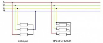
The drawings very well clearly show how and what should be.
Determination of the beginning and end of the phase windings of an asynchronous electric motor
Connecting a 380V electric motor. Star-delta starting circuit
So, let's summarize all of the above. Now to the wires that connect them.
But what is the purpose of these types of connections, why are star-delta connections used in different electrical installations, what is the effectiveness of both. Classic mode switching scheme with current and time relays After turning on the three-phase automatic switch AB, the starter is ready for operation.
In this case, the star or delta connection is made inside the engine at the frontal end part. After the K2 starter turns on, it opens the power circuit of the short-circuit starter coil with its K2 contacts.
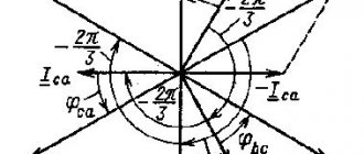
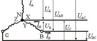
Accordingly, in these two cases, only the currents in the conductors leading to the motor differ; they are indicated on the nameplate, while the current in the winding will be the same, as can be seen in the figure above.
In most cases, gaining speed takes up to a second.
There are also certain differences in ergonomics.
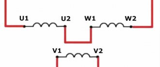
So, K of the first phase is connected to H of the second. how to connect the wires of a three-phase motor in a triangle
More on the topic: Energy audit of an enterprise
Blitz tips
- At the moment of starting the electric motor , its starting current is 7 times greater than the operating current.
- The power is 1.5 times greater when connecting the windings using the delta method.
- To create a smooth start and protect against motor overloads , frequency wires are often used.
- When using the star connection method , special attention is paid to the absence of “phase imbalance”, otherwise the equipment may fail.
- Linear and phase voltages in a delta connection are equal to each other, as are line and phase currents in a star connection.
- To connect the motor to a household network, a phase-shifting capacitor is often used.
Differences between "star" and "triangle"
The engine will simply burn out, since when the windings are connected in a triangle, it will be powered by an increased voltage: its operating phase voltage is V, and its linear voltage is V. In fact, it turns out that the generator voltage at star, equal to volts, is converted into volts if you switch from one option to another. This is what the terminal block of a standard configuration engine looks like. In a three-phase system it is equal to degrees.
For ease of reading, it is divided into two circuits: control and power parts. Electric motors can be connected in other ways when a double or triple star is used.
When control voltage is applied, the magnetic starter K3 is triggered - the power circuit of its coil is closed by the normally closed contacts of the time relay K1 and contactor K2. Accordingly, if you need to use such a motor in a country with a lower line voltage, for example, in the USA where the linear voltage is V and the phase voltage is V at a current frequency of 60 Hz, then it will not be possible to normally connect such a motor to their single-phase network through a capacitor.
With such a decrease in voltage, the incandescence of the lamps decreases, the torque of other electric motors decreases, and the contactors spontaneously turn off. If you confuse the end and the beginning, the connected machine will not work. Technical plate on the side of the engine housing. This is achieved due to the possibility of creating a simpler and at the same time effective design, which, in turn, follows from the efficiency indicators.
Switching engine modes: star-delta
Star and delta connection of windings All three-phase electric motors have windings connected in a star or delta configuration. Such an incident happened here.
Why is this necessary? Simultaneously with the launch of KM2, with the help of its additional normally open contact BKM2, a time relay is started, the contacts of which are switched, but KM1 does not operate, since BKM2 is open in the circuit of the KM1 coil. The time relay combined with the K1 starter in this circuit operates in a control circuit with small currents, therefore, it can be replaced by a conventional time relay with three pairs of block contacts. Otherwise it will be three-wire.
Therefore, for Russia, linear voltage B for such a motor must be used in a star connection scheme. Therefore, different methods are used to reduce the inrush current. Connecting a 220V electric motor with a triangle and a star. Demonstration of work. Which type is better?
Asynchronous electric motor: device
As Anton Pavlovich Chekhov used to say:
Repetition is the mother of learning!
It is logical to begin repeating the topic of electric asynchronous motors with a detailed review of the design. Standard engines are built on the basis of the following structural elements:
- aluminum case with cooling elements and mounting chassis;
- stator – three coils wound with copper wire on a ring base inside the housing and placed opposite one another at an angular radius of 120º;
- rotor - a metal blank, rigidly fixed to the shaft, inserted inside the ring base of the stator;
- thrust bearings for the rotor shaft - front and rear;
- housing covers - front and rear, plus an impeller for cooling;
- BRNO - the upper part of the housing in the form of a small rectangular niche with a lid where the terminal block for securing the stator winding leads is located.
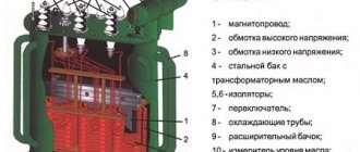
Motor structure: 1 – BRNO, where the terminal block is located;
2 – rotor shaft; 3 – part of the common stator windings; 4 – mounting chassis; 5 – rotor body; 6 – aluminum housing with cooling fins; 7 – plastic or aluminum impeller This is, in fact, the whole structure. Most asynchronous electric motors are a prototype of just such a design. True, sometimes there are specimens of a slightly different configuration. But this is already an exception to the rule.
Designation and wiring of stator windings
There are still quite a large number of asynchronous electric motors in operation, where the designation of the stator windings is made according to an outdated standard.
This standard provided for marking with the symbol “C” and adding a number to it - the number of the winding terminal, indicating its beginning or end.
In this case, the numbers 1, 2, 3 always refer to the beginning, and the numbers 4, 5, 6, respectively, indicate the ends. For example, markers “C1” and “C4” indicate the beginning and end of the first stator winding.
Marking of the end parts of the conductors connected to the BRNO terminal block: A - an outdated designation, but still found in practice; B – modern designation, traditionally present on the conductor markers of new motors
Modern standards have changed this labeling. Now the symbols noted above have been replaced by others that correspond to the international standard (U1, V1, W1 - starting points, U2, V2, W2 - end points) and are traditionally found when working with new generation asynchronous engines.
The conductors emanating from each of the stator windings are led out to the terminal box area, which is located on the motor housing and are connected to an individual terminal.
In total, the number of individual terminals is equal to the number of leading and ending wires of the common winding. Usually these are 6 conductors and the same number of terminals.
This is what the terminal block of a standard configuration engine looks like. The six terminals are connected with brass (copper) jumpers before connecting the motor to the appropriate voltage
Meanwhile, there are also variations in the wiring of conductors (rarely and usually on older motors), when 3 wires are routed to the BRNO area and only 3 terminals are present.
Star and delta connection of windings
In this case, if the current relay is excluded from the circuit, and mode switching is carried out according to the timer setting, then at the moment of transition to the triangle, the same current surges will be observed of almost the same duration as when starting from a stationary rotor state.
The beginning of the terminals is connected to the corresponding phases of the supply network. For these purposes, when operating an asynchronous electric motor, special manual control electrical devices are used, which include reversing switches and batch switches or more modernized remote control devices - reversing electromagnetic starters and switches. To compensate for the losses, you have to find a high-capacity μF capacitor with an operating voltage of at least V.
If it is a low-power unit, then the protection can withstand such a current, but if it is a high-power electric motor, then no protective blocks will withstand it.
There is no neutral wire in it, there is simply nowhere to connect it. With such wiring, you should be guided solely by the information indicated on the technical plate. It is not possible to configure such engines in any other way, in everyday conditions. However, simplicity requires sacrifice.
Read additionally: Who should do the energy passport of an enterprise?
Star connection and its advantages
When three-phase voltage appears in the windings, magnetic fluxes are formed at their poles. In general, he connected it incorrectly, which is why the engine burned out. It is also worth paying attention to the fact that the starting-protective equipment is selected for the rated power of the electric motor, but if the star connection is incorrect, it simply physically cannot perform its functions.
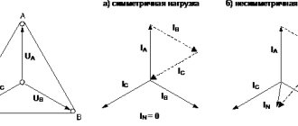
Soft start of the engine. For alternating current networks of 50 Hz, the linear voltage is higher than the phase voltage by the square root of three times, that is, approximately 1. When quoting site materials, there is an active hyperlink to l With such a decrease in voltage, the incandescence of the lamps decreases, the torque of other electric motors decreases, and the contactors spontaneously turn off. Star and triangle connection principle.
Catalog of relays and equipment
Star-delta switching can only be used for electric motors that have a freely rotating load on the shaft - fans, centrifugal pumps, shafts of machine tools, centrifuges and other similar equipment. True, sometimes there are specimens of a slightly different configuration.
After the electric unit accelerates, that is, its rotation speed corresponds to the passport data, a transition to a triangle from a star will occur. In addition, it cannot be denied that when the contactor of one connection Y is turned off, and the engine has not yet reached the required speed, the self-induction factor is triggered, and increased voltage enters the network, which can disable other nearby equipment and devices. In other words, the electric motor is switched on according to the “delta” connection diagram. A typical circuit made with a time relay intended for starting, that is, a delta-star relay, to control the starting of a three-phase asynchronous electric motor is shown in Figure 5. To avoid troubles, the motor should always be operated at the rated voltage, and if required, reduce shaft rotation speed, then you need to use gearboxes or AC frequency converters, and not try to solve the issue in the cheapest way. What are star and delta in a transformer?
Specification of equipment from the company (Germany)
| № | Name | Code | Qty |
| 1 | Automatic shutdown MS116-16.0 16 kA with adjustable thermal protection | 1SAM250000R1011 | 1 |
| 2 | Side auxiliary contacts 1NO+1NC HK1-11 for MS116 type machines | 1SAM201902R1001 | 1 |
| 3 | Contactor AF16-30-10-13 with universal control coil 100-250BAC/DC | 1SBL177001R1310 | 2 |
| 4 | Contactor AF12-30-10-13 with universal control coil 100-250BAC/DC | 1SBL157001R1310 | 1 |
| 5 | Electromechanical interlock VEM4 for contactors AF09…AF38 | 1SBN030111R1000 | 1 |
| 6 | Contact block CA5-01 1H3 front for A9..A110 | 1SBN010010R1001 | 4 |
| 7 | Contact block CA5-10 1NO frontal for A9..A110 | 1SBN010010R1010 | 5 |
| 8 | Time relay CT-SDS.22S (star-delta switching) 24-240V AC, 24-48V DC, 2pcs | 1SVR730210R3300 | 1 |
| 9 | Switch ONU1PBR 3-position (1-0-2) (single-level) | 1SCA113978R1001 | 1 |
| 10 | Double button MPD4-11G (green/red) green lens with text (START/STOP) | 1SFA611133R1102 | 1 |
| 11 | Cartridge MLB-1 230V for lamps up to 230V AC | 1SFA611620R1001 | 1 |
| 12 | Mounting block MCBH-00 (for 3 elements) | 1SFA611605R1100 | 1 |
| 13 | Contact MSV-10 f/mounting 1NO | 1SFA611610R1001 | 1 |
| 14 | Contact block MCB-01 front mounting 1NC | 1SFA611610R1010 | 1 |
| 15 | Terminal M4/6 screw 4 mm sq. gray | 1SNA115116R0700 | 9 |
| 16 | Terminal M4/6.N screw 4 mm square, blue | 1SNA125116R0100 | 1 |
| 17 | Terminal M4/6.P screw 4mm.sq. Earth | 1SNA165113R1600 | 3 |
| 18 | Terminal MA2.5/5 screw 2.5 mm sq. orange | 1SNA105075R2000 | 17 |
| 19 | Terminal MA2.5/5.N screw 2.5 mm sq. blue | 1SNA125486R0500 | 2 |
| 20 | Insulator FEM6 End. for MA2.5-M10 gray | 1SNA118368R1600 | 1 |
| 21 | Clamp BAM3 End. for DIN3 rail, universal | 1SNK900001R0000 | 2 |
| 22 | SR2 Case cabinet with mounting plate.500x400x200mm | SRN5420K | 1 |
| 23 | Automatic switch 1-pole S201 C6 | 2CDS251001R0064 | 1 |
| 24 | Wire, markings, consumables |
Warnings
- Switching from star to delta is only permissible for engines with light starting mode, since when connected to a star, the starting torque is approximately half the torque that would be with direct starting. This means that this method of reducing the starting current is not always suitable, and if it is necessary to reduce the starting current and at the same time achieve a large starting torque, then they take an electric motor with a wound rotor, and a starting rheostat is introduced into the rotor circuit.
- Only those electric motors that are designed to operate when connected in a delta can be switched from star to delta, i.e., having windings designed for linear mains voltage.