It is impossible to imagine a repairman's workbench without a convenient, inexpensive digital multimeter. This article discusses the design of digital multimeters of the 830 series, the most common faults and methods for eliminating them.
Currently, a huge variety of digital measuring instruments of varying degrees of complexity, reliability and quality are produced. The basis of all modern digital multimeters is an integrated analog-to-digital voltage converter (ADC). One of the first such ADCs suitable for building inexpensive portable measuring instruments was a converter based on the ICL71O6 chip, produced by MAXIM. As a result, several successful low-cost models of digital multimeters of the 830 series were developed, such as M830B, M830, M832, M838. Instead of the letter M there may be DT. Currently, this series of devices is the most widespread and most repeated in the world. Its basic capabilities: measuring direct and alternating voltages up to 1000 V (input resistance 1 MOhm), measuring direct currents up to 10 A, measuring resistances up to 2 MOhm, testing diodes and transistors. In addition, some models have a mode for audibly testing connections, measuring temperature with and without a thermocouple, and generating a meander with a frequency of 50...60 Hz or 1 kHz. The main manufacturer of multimeters in this series is Precision Mastech Enterprises (Hong Kong).
Why is the mode called “dialing”?
It was possible to check the integrity of the circuit before using the resistance measurement mode - an ohmmeter. The main difference between dialing is that during measurements, if there is an electrical connection between the tested areas, then, in addition to the readings on the screen, a sound signal is heard - a buzzer, which is where the term dialing or ringing came from.
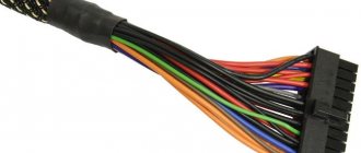
This sound signal significantly speeds up the verification process, you don’t have to be distracted, look at the screen, and it’s not always convenient, and when you hear the buzzer (or not), you already know the result. This is especially useful for mass measurements, for example, when searching for one specific wire in a bundle.
Safety precautions
- You should definitely read the instructions for the device.
- Avoid touching parts with your fingers. The human body has its own resistance, which can affect the accuracy of the measurement.
- You need to wear non-conductive gloves when measuring. If there are none, dense rubberized models are suitable.
- If there is high humidity at the measurement site, it should not be carried out.
- When a measurement is being taken, modes cannot be switched.
- In case of mechanical damage or deformation of the braiding of wires and probes, the device cannot be used.
Multimeter, an affordable and simple device for home use. It allows you to accurately measure parameters. This contributes to safe and convenient work with the electrical network, and also ensures the serviceability of household appliances.
{SOURCE}
Continuity indication on a multimeter
In one of the recent articles - “How to use a multimeter”, I already talked about the main operating modes of a standard tester, measurement limits and testing methods, in particular about the dialing function, which has the following designation:
As you can see, the marking accurately conveys the main meaning of this mode, because it consists of two elements - a diode icon, which symbolizes the test, and a buzzer, indicating a sound signal.
General purpose
This is a multifunctional device designed to measure a number of electrical current parameters. A modern multimeter, even a semi-professional one intended for household needs, is capable of measuring:
This is a minimum list of functions that even the simplest device has. More complex ones have functions for testing diodes and transistors, checking cable integrity, etc. There are models that even allow you to measure temperature.
An ordinary household appliance is used in networks whose voltage is not higher than 1000 volts DC or 750 volts AC. To measure high voltage, only a professional high-voltage multimeter is used.
A multimeter is a universal measuring instrument that can measure several electrical quantities. The list of measurements depends on the model and may vary significantly. The basic set of functions is the determination of current (DC and AC), voltage, resistance. Such devices are relatively inexpensive.
https://www.youtube.com/watch?v=sFvLYuZegS8
In general, you can find models that can determine the capacitance of capacitors, current frequency, temperature, can ring diodes, determining the voltage drop across the PN junction, generate signals of a certain frequency, etc. The more possible features, the higher the price. The price also depends on the degree of “promotion” of the brand and on the build quality.
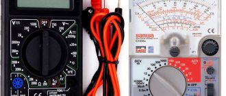
Multimeters are either dial or electronic
There are also two types of multimeters: with a dial indicator and a digital indicator. Models with digital display are more popular - information is easier to read.
As you can see, there can be so many functions that the question arises: “How to use a multimeter?” This is what we will talk about next.
Operating principle of dialing
For a better understanding of how exactly the multimeter finds out whether there is an open circuit or not, I will, in general terms, describe the principle of operation of this mode.
Everything here is extremely simple, the operating principle of dialing is based on the well-known Ohm’s law, the main rule of electrical engineering:
I = U / R , where I – current, U – network voltage, R – resistance
Each multimeter has a power source - a battery or an accumulator, with the help of which a voltage is created on the section of the network being tested - a current is supplied and, knowing its characteristics, the result is calculated.
Connecting plugs
Before measuring voltage, the multimeter must be set to the appropriate mode. To mark voltage, either the abbreviations ACV - alternating, and DCV - constant, or pictograms that complement the designation V - voltage are used. Yes, V
- this is alternating voltage. V with a horizontal long line, under which there are three short ones - this is a constant.
Note! If your device only has the designation V, then it is capable of automatically determining whether it is alternating or constant. In addition to pictograms indicating the type of voltage, ranges of values are marked on the body of the multimeter. Most household appliances have measurement limits of up to 750 V AC and up to 1000 V DC.
Before measuring the voltage in an outlet, battery or other device, connect the probes to the multimeter. There are two of them - black and red. But there can be two, three, or four sockets, depending on the class of the device.
The black probe is either negative or zero. It is always installed in the multimeter socket marked COM. The red probe is either positive or “phase”. To connect it, select a socket equipped with appropriate markings. If there are only 2 slots, the question is removed; if there are more, choose the one with the V symbol next to it.
Other sockets can be marked either 10-20A or mA - respectively for measuring current strength (extra-high or ultra-low), or have other designations and, accordingly, purposes. There is always one voltage socket.
What does the multimeter show when making a call?
The multimeter, when tested, shows the calculated voltage drop in millivolts in this circuit.
The current created by the tester in the area being tested, about 1 milliampere, was not chosen by chance, since the voltage drop in millivolts in this case corresponds to the resistance in Ohms.
In other words, when testing electrical circuits or electrical materials, we are shown the magnitude of the voltage drop, which is equal to the resistance of this section in Ohms.
Testing the wire with a multimeter
1. Install the probes into the multimeter connectors:
— Red probe into the V Ω mA
— Black probe into COM
2. We switch the control wheel to dialing mode, which is marked accordingly (diode and buzzer icon). One should appear on the screen.
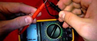
3. We check the correct operation of the multimeter by connecting the contacts of the probes by shorting them.
If the device is working correctly, you will hear a buzzer sound and a value close to zero will appear on the screen.
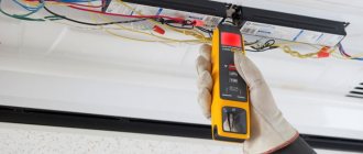
4. We call the wire. By applying the multimeter probes to its wires on both sides, as shown in the image below. If the conductor is intact, then you will immediately hear a buzzer sound, and the readings on the screen will be close to “0”, for example 0.001.
If the wire core is damaged and one of its ends does not have an electrical connection with the other, then the multimeter readings will not change, “1” will be displayed and there will be no sound signal.
As you can see, everything is quite simple, and if you have a multimeter at hand, you can try to ring something yourself. Just let me remind you once again - do not call under voltage, even under low voltage.
One of the clear, often found in everyday life, examples of checking wiring with a multimeter is described in our next article - HOW TO RING AN OUTLET. This is a detailed, step-by-step instruction for diagnosing a non-working outlet; be sure to study it to understand how to connect the electrical wiring.
External device
We will consider digital multimeters (aka testers) because... analogue ones (equipped with an arrow and a field with a scale of values) are now almost out of use.
There are a wide variety of multimeters on the market, but they all have the following elements:
- digital display;
- switch for setting parameters;
- 2-4 sockets for connecting contact probes;
- two contact probes.
The device operates on a battery. We will consider the simplest multimeter for home use, which measures three main parameters - voltage, current and resistance of an electrical conductor. The vast majority of other functions in everyday life are not needed, with the exception of the dialing function. But before we move on to measuring voltage, let's figure out what it is.
Multimeters are also called testers or multitesters, as they allow you to measure several different parameters and characteristics. But when they say “tester,” they usually mean a device with a dial indicator. They are used infrequently, since the values have to be calculated on a scale, taking into account the set threshold of the measuring scale.
Just looking at the screen is easier than calculating readings on a scale
When using a digital device with a liquid crystal display, these problems do not exist - the result is ready-made. This is why, basically, everyone uses multimeters. Before we learn how to use a multimeter, let's understand its structure. This will allow you to quickly master the skills of working with this measuring device.
A digital multimeter is a small device, less than half the size of a notebook sheet. It weighs 200-300 grams. At the top there is a display that shows measurement readings. In the central part of the case there is a switch, with the help of which the nature of the measurements and their limits are set.
Appearance of the multimeter
Most often there are three connectors. The bottom one is usually signed “COM” - general. The black probe is always connected here. The other two are for connecting the red probe. The upper socket is used only in one case: when measuring direct current, the value of which is more than 200 mA. All other measurements with a multimeter are carried out when the second probe is in the middle position.
There are models in which there are four measuring sockets (pictured on the left). In this case, there are separate sockets for measuring current up to 200 mA, and separately for current from 200 mA to 10 A (the numbers may change depending on the model, but the meaning remains the same). There is its own socket for resistance and voltage. All sockets are labeled, it’s not very difficult to figure it out.
In order to understand how to use a multimeter, you need to carefully examine the mode switch, consider where and what symbols and modes are.
Multimeter operating mode switch
The number and position of modes depends on the model, but most of them contain:
- OFF position—turns off the device.
- ACV - for measuring alternating voltage. Some models may have the letter V and a wave underneath it.
- DCA - for direct current up to 200 mA. Can be denoted by a Latin A and a straight line underneath it.
- 10 A - for direct current from 200 mA to 10 A (in some models these figures may be different).
- HFE - for checking the gain of transistors. This mode is not available in all models.
- Image of a diode or megaphone - a socket for testing wires and checking diodes.
- Ω - resistance measurement.
- DCV - constant voltage. There may be a V with a straight line underneath.
These are all the main modes. As you can see, most of them have several provisions. These positions define the upper measurement limit.
What to do if the multimeter does not have a dialing mode
Some budget electronic testers do not have a separate dialing mode with a sound alert, but they can also check the integrity of the circuit , but this is not so convenient.
For example, the fairly popular dt 830b does not have a buzzer, but there is a diode test mode, you can use it by observing the change in readings on the screen. The probes are connected in the same way as described above into the COM and V Ω mA .
If the readings on the screen during measurements differ from one, then there is an electrical connection in the area being tested. You can check the functionality of this method by connecting the probes; if everything is in order, then zeros should appear on the screen.
In multimeter models, where there are no additional functions at all, in particular in analog instruments, you can ring by switching the regulator to the resistance measurement mode - ohmmeter.
In this case, it is necessary to select the lowest available threshold - for example, 50 Ohms or 200 Ohms. Then measure according to the usual scheme described above and watch the changes in the readings on the screen - if there are changes, the circuit is intact. For home, everyday conditions, this is quite enough to find which wire is broken, determine the burnt track on the board, and much more.
That's all for me; in my opinion, this information is quite enough for anyone to learn how to dial with a multimeter, even without ever doing it before. If you still have questions or have healthy criticism or additions, be sure to write in the comments to the article, in addition, subscribe to our VKONTAKTE group - stay tuned for new materials.
In the following articles we will talk about other useful functions and ways to use a digital multimeter in everyday life, determine the phase and zero in an outlet, measure the voltage in the network and much more, stay tuned .
It is impossible to imagine a repairman's workbench without a convenient, inexpensive digital multimeter. This article discusses the design of digital multimeters of the 830 series, the most common faults and methods for eliminating them.
Currently, a huge variety of digital measuring instruments of varying degrees of complexity, reliability and quality are produced. The basis of all modern digital multimeters is an integrated analog-to-digital voltage converter (ADC). One of the first such ADCs suitable for building inexpensive portable measuring instruments was a converter based on the ICL71O6 chip, produced by MAXIM. As a result, several successful low-cost models of digital multimeters of the 830 series were developed, such as M830B, M830, M832, M838. Instead of the letter M there may be DT. Currently, this series of devices is the most widespread and most repeated in the world. Its basic capabilities: measuring direct and alternating voltages up to 1000 V (input resistance 1 MOhm), measuring direct currents up to 10 A, measuring resistances up to 2 MOhm, testing diodes and transistors. In addition, some models have a mode for audibly testing connections, measuring temperature with and without a thermocouple, and generating a meander with a frequency of 50. 60 Hz or 1 kHz. The main manufacturer of multimeters in this series is Precision Mastech Enterprises (Hong Kong).
How to measure electrical parameters
Sometimes in everyday life there is a need to measure the network voltage. It is often necessary to find a phase or find out whether the electrical wire is working at all. If such a situation arises, it is good to know and be able to use a device capable of performing the necessary manipulations.
Voltage, or voltage, is one of the parameters of electric current that shows the potential difference in a section of the circuit. It is equivalent to electromotive force, and in fact is one of the most important factors for the operation of any electrical appliance.
Checking the voltage is perhaps the most common operation that has to be performed when working with electrical equipment, regardless of whether it is servicing an industrial or household (home) electrical network. Its size, as well as the very fact of its presence, determines whether the electrical appliance will work, and whether it can fail. Currently, a device called a multimeter is used to measure voltage.
After installing the probes, set the multimeter switch to the appropriate range. If you are measuring the voltage at an outlet, choose a threshold value of 750 ACV, if, for example, a car battery is 20 or 200 DCV.
Note! It is always necessary to set the measurement limit higher than the expected voltage at the power supply. Otherwise, you risk burning the device.
There is a rule: voltage is measured by connecting a multimeter in parallel (while current strength is measured in series with the load). In practice, this means that in order to measure the voltage in an outlet, you simply need to insert both multimeter probes into it, each into its own socket. Where the zero is, where the phase is, it doesn’t matter.
The device shows the voltage within the limits to which it is adjusted. Thus, if you set the upper threshold to 750 V, you will see on the screen a value in the range of 210-230 V. Or less, or more, if the voltage surge is very large, but it cannot rise above 750 V. But if you set the threshold to 200 V, then when the actual voltage value is above this limit, the number 1 will appear on the screen.
Please note that there is not always exactly 220 V in a household outlet. Deviations of plus or minus 10-15 V are acceptable.
Testing a three-phase line is carried out by contacting two multimeter probes with two buses. Between them there should be 380 V, between one bus and the ground there will be 220 V (plus or minus 15).
Before we start talking about how to use a multimeter, we need to remember that when measuring current, the multimeter is connected in series - into an open circuit, and when measuring voltage - in parallel with respect to a section or element of the circuit.
Measuring voltage
We move the switch to the voltage measurement position. There are two positions: for direct and alternating voltage. We select according to the parameters of the circuit or device.
Next you need to select the measurement range. To do this, you need to at least roughly (or better yet, exactly) know what readings to expect. For example, when measuring the voltage in the network, you know that there will be 220 V or There are inscriptions on the batteries or accumulators, and there are nameplates on the devices indicating the parameters of the circuit. In any case, we set a limit - the nearest larger one. This will provide greater accuracy.
Multimeter connection diagrams for measuring various electrical quantities
If we don’t know exactly what the voltage might be, we set it approximately - after the first readings we can change it. If we have no idea at all about the voltage value, we set the highest limit, further approaching the desired position. This algorithm will not allow the device to burn out, which can happen if you set the limit too low.
Having decided on the limits of change, we connect the probes:
- black to the common “COM” socket, and the second probe to the minus of the battery or accumulator;
- red into the socket labeled VΩmA, and the probe from it to the plus of the battery.
The numbers appear on the display. This is the voltage in the measured area. In this case, on a battery/accumulator.
To measure voltage, you need to move the switch to the desired position
If you swap the probes and connect the red one to the positive and the black to the negative, nothing bad will happen. A minus sign will simply appear in front of the readings.
Most often, for measuring current, there are two switch positions - constant and alternating. But not in all models. There are devices (M-830, DT-830) that can only measure direct current.
To measure direct current with a multimeter, the procedure is standard:
- We set the switch to the appropriate position.
- We select the measurement limit (we set approximately the expected current value).
- We install the measuring probes: black in the “COM” socket;
- red
- to the VΩmA socket if the expected current is less than 200 mA;
to the third socket if the current is more than 200 mA.
How to measure direct current with a multimeter
- We connect the multimeter to the open circuit. To do this, use the free ends of the probes to touch both conductors at the break point, closing the circuit through the device.
- We take readings from the display.
One note: the assembly of the measuring circuit when measuring current must be carried out with the voltage removed. At significant currents (above 200 mA), operation without voltage relief is unsafe. Power must be supplied only after the multimeter is connected.
The position of the multimeter probes for measuring resistance is standard: red in the “COM” socket, black in VΩmA. The free ends of the probes touch the terminals of the object being measured.
There are nuances with the choice of measurement limit. If you know what the readings should be (checking resistors, for example), set the measurement limit to the nearest larger one. If the resistance value is unknown, move the switch to the maximum scale. After measurement, it can be changed to a more suitable one.
How to measure resistance with a multimeter
If, when measuring resistance with a multimeter, the number “1” appears on the screen, this means that the measurement limit has been exceeded, you need to change it to a higher one.
Scheme and operation of the device
Rice. 1. Block diagram of ADC 7106
The basis of the multimeter is the ADC IC1 type 7106 (the closest domestic analogue is the 572PV5 microcircuit). Its block diagram is shown in Fig. 1, and the pinout for execution in the DIP-40 housing is shown in Fig. 2. The 7106 core may have different prefixes depending on the manufacturer: ICL7106, TC7106, etc. Recently, DIE chips have been increasingly used, the crystal of which is soldered directly onto the printed circuit board.
Defects of multimeters
All malfunctions can be divided into manufacturing defects (and this happens) and damage caused by erroneous operator actions.
Since multimeters use dense mounting, short circuits of elements, poor soldering and breakage of element leads are possible, especially those located at the edges of the board. Repair of a faulty device should begin with a visual inspection of the printed circuit board. The most common factory defects of M832 multimeters are shown in the table.
Factory defects of M832 multimeters
| Defect manifestation | Possible reason | Troubleshooting |
| When you turn on the device, the display lights up and then goes out smoothly | Malfunction of the master oscillator of the ADC chip, the signal from which is supplied to the LCD display substrate | Check elements C1 and R15 |
| When you turn on the device, the display lights up and then goes out smoothly. The device works normally when the back cover is removed. | When the back cover of the device is closed, the contact helical spring rests on resistor R15 and closes the master oscillator circuit | Bend or shorten the spring slightly |
| When the device is turned on in voltage measurement mode, the display readings change from 0 to 1 | The integrator circuits are faulty or poorly soldered: capacitors C4, C5 and C2 and resistor R14 | Solder or replace C2, C4, C5, R14 |
| The device takes a long time to reset the readings to zero | Low quality capacitor SZ at the ADC input (pin 31) | Replace the SZ with a capacitor with a low absorption coefficient |
| When measuring resistances, the display readings take a long time to settle | Poor quality of capacitor C5 (automatic zero correction circuit) | Replace C5 with a capacitor with a low absorption coefficient |
| The device does not work correctly in all modes, the IC1 chip overheats. | The long pins of the connector for testing transistors are shorted together | Open the connector pins |
| When measuring alternating voltage, the instrument readings “float”, for example, instead of 220 V they change from 200 V to 240 V | Loss of capacitance of the capacitor SZ. Possible bad soldering of its terminals or simply the absence of this capacitor | Replace the SZ with a working capacitor with a low absorption coefficient |
| When turned on, the multimeter either beeps constantly, or vice versa, remains silent in connection testing mode | Poor soldering of the Yu2 microcircuit pins | Solder the pins of IC2 |
| Segments on the display disappear and appear | Poor contact of the LCD display and the contacts of the multimeter board through the conductive rubber inserts | To restore reliable contact you need to: • correct the conductive rubber bands; • wipe the corresponding contact pads on the printed circuit board with alcohol; • irradiate these contacts on the board |
The serviceability of the LCD display can be checked using an alternating voltage source with a frequency of 50.60 Hz and an amplitude of several volts. As such an alternating voltage source, you can take the M832 multimeter, which has a meander generation mode. To check the display, place it on a flat surface with the display facing up, connect one probe of the M832 multimeter to the common terminal of the indicator (bottom row, left terminal), and apply the other probe of the multimeter alternately to the remaining terminals of the display. If you can get all segments of the display to light up, it means it is working.
The malfunctions described above may also appear during operation. It should be noted that in the DC voltage measurement mode, the device rarely fails, because Well protected from input overloads. The main problems arise when measuring current or resistance.
Repair of a faulty device should begin with checking the supply voltage and the functionality of the ADC: stabilization voltage of 3 V and the absence of breakdown between the power pins and the common terminal of the ADC.
Possible faults
If the multimeter stops measuring voltage or shows it incorrectly, check the battery located inside the case with another tester, or simply replace it. Also check whether the set measurement threshold corresponds to the voltage that the object you are testing should have. Check whether the voltage is set correctly - the battery is not tested in AC mode, and the socket is not tested in DC voltage mode.
If the parameter is not detected in one outlet, check it in another. If the problem arose when testing a small battery, it may be due to poor contact between the probe and the terminal.
Test the device on various objects that are a priori operational. If the multimeter basically stops measuring voltage, then either its built-in current source has dried up, or the control board is damaged, or - the most common case - the cable of one of the probes is damaged. You should inspect the cables for breaks and ensure good contact with the socket. If a break is detected, replace or repair the wire, restoring its integrity.
If no visible reasons for the loss of performance are found, then most likely the multimeter has burned out. This could happen due to an attempt to measure too high voltage, or a powerful network surge, or other reasons.
Since modern ADCs are most often produced in an integrated version (without a housing), rarely can anyone replace them. So if the converter burns out, then it will not be possible to repair the multimeter; it cannot be repaired.
Visually detectable defects (manufacturing defects)
It is most convenient to check the serviceability of the device at the initial stage of repair by examining its electronic circuit. For this case, the following troubleshooting rules have been developed:
- it is necessary to carefully examine the printed circuit board of the multimeter, which may have clearly visible factory defects and errors;
- Particular attention should be paid to the presence of unwanted short circuits and poor-quality soldering, as well as defects on the pins along the edges of the board (in the area where the display is connected). For repairs you will have to use soldering;
- Factory errors most often manifest themselves in the fact that the multimeter does not show what it should according to the instructions, and therefore its display is examined first.
If the multimeter gives incorrect readings in all modes and the IC1 chip heats up, then you need to inspect the connectors to check the transistors. If the long leads are shorted, then the repair will simply consist of opening them.
In total, there can be a sufficient number of visually detectable faults. You can familiarize yourself with some of them in the table and then eliminate them yourself. (at: https://myfta.ru/articles/remont-multimetrov.) Before repairs, you need to study the multimeter diagrams, which are usually given in the passport.
Checking the display
If they want to check the serviceability and repair the multimeter indicator, they usually resort to the help of an additional device that produces a signal of a suitable frequency and amplitude (50-60 Hz and units of volts). If it is not available, you can use a multimeter type M832 with the function of generating rectangular pulses (meander).
To diagnose and repair the multimeter display, you need to remove the working board from the device body and select a position convenient for checking the indicator contacts (screen up).
After this, you should connect the end of one probe to the common terminal of the indicator under study (it is located in the bottom row, far left), and with the other end, alternately touch the signal terminals of the display.
In this case, all its segments should light up one after another according to the wiring of the signal buses, which should be read separately. Normal “activation” of the tested segments in all modes indicates that the display is working properly.
Additional Information. This malfunction most often manifests itself during the operation of a digital multimeter, in which its measuring part fails and requires repair extremely rarely (provided that the requirements of the instructions are met).
The last remark concerns only constant quantities, when measuring which the multimeter is well protected against overloads. Serious difficulties in identifying the causes of device failure most often occur when determining the resistance of a circuit section and in testing mode.
Problems related to resistance testing
In this mode, characteristic faults, as a rule, appear in measuring ranges up to 200 and up to 2000 Ohms. When extraneous voltage comes into contact with the input, as a rule, resistors designated R5, R6, R10, R18, as well as transistor Q1, burn out. In addition, capacitor C6 often breaks through. The consequences of exposure to extraneous potential are manifested as follows:
- when triode Q1 is completely “burnt out”, when determining the resistance, the multimeter shows only zeros;
- in case of incomplete breakdown of the transistor, the device with open ends should show the resistance of its transition.
In other measurement modes, this transistor is short-circuited and therefore does not affect the display readings.
In the event of a breakdown of C6, the multimeter will not work at the measuring limits of 20, 200 and 1000 Volts (the possibility of a strong underestimation of readings is not excluded).
If the multimeter constantly beeps when dialing or is silent, then the cause may be poor-quality soldering of the pins of the IC2 microcircuit. Repair involves careful soldering.
What voltage standards exist?
Existing standards for the operation of electrical systems describe voltage values as applied to residential premises. According to GOST, the normal voltage in residential buildings is 220V +/- 10%. Therefore, household electrical appliances are usually designed for voltages up to 240 volts.
Note! When this value rises above the required level or decreases beyond the permissible percentage, you need to disconnect all electrical appliances from the power supply and check the exact voltage parameter.
To assess the electricity at the input (for example, near the meter), that is, that which comes in “from the street” and is not influenced by powerful energy consumers or long electrical wiring, there are several parameters.
Unfortunately, a multimeter can only determine one, but the most important one is permanent deviation. This deviation during normal operation should not be more than 5% of the rated voltage value for a long period of time and rise above 10% for a short period. These parameters are set by the service provider and are reflected in the service agreement. Most likely, this is a corridor installed within 198-220 volts.
Problems with the ADC
It is recommended to begin the inspection and repair of a non-working multimeter, the malfunction of which is not related to the cases already considered, by checking the 3 Volt voltage on the ADC supply bus. In this case, first of all, you need to make sure that there is no breakdown between the supply terminal and the common terminal of the converter.
The disappearance of indication elements on the display screen in the presence of a supply voltage to the converter most likely indicates damage to its circuit. The same conclusion can be drawn if a significant number of circuit elements located near the ADC burn out.
In practice, this unit “burns out” only when a sufficiently high voltage (more than 220 Volts) is applied to its input, which manifests itself visually in the form of cracks in the module’s compound.
Distribution box
This is an important element of the food chain. It is used to route wires to switches, lighting and sockets. The wiring is carried out from the secondary input wire to the consumers. Often the connection of such boxes is done using twisting or contactors. To carry out the check you must:
- Turn off the main power to the circuit.
- Open the box.
- Check connections.
ADC testing
Before we talk about repairs, it is necessary to carry out an inspection. A simple way to test an ADC for suitability for further operation is to test its outputs using a known-good multimeter of the same class. Note that the case when the second multimeter incorrectly displays measurement results is not suitable for such a test.
When preparing for operation, the device is switched to the diode “testing” mode, and the measuring end of the wire in red insulation is connected to the “minus power” terminal of the microcircuit. Following this, each of its signal legs is successively touched with a black probe.
Since the circuit inputs have protective diodes connected in the reverse direction, they should open after applying forward voltage from a third-party multimeter.
The fact of their opening is recorded on the display in the form of a voltage drop across the junction of the semiconductor element. The circuit is checked in the same way by connecting a probe in black insulation to pin 1 (+ ADC power supply) and then touching all other pins. In this case, the readings on the display screen should be the same as in the first case.
When changing the polarity of the connection of the second measuring device, its indicator always shows a break, since the input resistance of the working microcircuit is quite high.
In this case, the terminals that in both cases show the final resistance value will be considered faulty. If, with any of the described connection options, the multimeter shows a break, this most likely indicates an internal break in the circuit.
Pointer or digital
Analog instruments are equipped with a dial indicator with several scales. Plus, they clearly display electrical quantities with rapidly changing indicators using an arrow.
With a digital multimeter, the data on the display is updated with some delay, so the device may not convey dynamic information at all.
Compared to digital ones, pointer instruments have a lot of disadvantages:
- Data with several decimal places is not displayed
- some scales are nonlinear (accuracy decreases, you need to pre-adjust and apply coefficients)
- It can be difficult to record readings visually along the arrow
- you have to wait for the arrow to stop
- need to control polarity
- few functions
Problems with the rotary switch
Repair will be required if problems arise due to loss of contact in the circular biscuit switch. This manifests itself not only in the fact that the multimeter does not turn on, but also in the inability to obtain a normal connection without pressing hard on the biscuit. This is explained by the fact that in cheap Chinese multimeters, the contact tracks are rarely covered with high-quality lubricant, which leads to their rapid oxidation.
When used in dusty conditions, for example, after some time they become dirty and lose contact with the switch bar. To repair this multimeter assembly, it is enough to remove the printed circuit board from its body and wipe the contact tracks with a cotton swab dipped in alcohol. Then a thin layer of high-quality technical Vaseline should be applied to them.
In conclusion, we note that if contacts are detected or shorted in the multimeter, these shortcomings should be eliminated by using a low-voltage soldering iron with a well-sharpened tip. If you are not completely sure of the cause of the device failure, you should contact a specialist in the repair of measuring equipment.
Why do you need to take measurements?
The electrical network is a dangerous and complex engineering system that requires operational skills and safety.
For a number of reasons, malfunctions and breakdowns may occur. To control and prevent them, it is necessary to carry out measurements. Also, breakdown or unstable operation of electrical appliances and equipment can be caused by a discrepancy between the mains voltage and the nominal voltage, and both excess and insufficient voltage can be dangerous.
What needs to be done to avoid overloading the electrical system - this can be achieved through the correct use of electrical equipment and measurements. Using a multimeter, you can determine the necessary parameters yourself, without involving qualified electrical laboratory specialists.