The presence of various electronic assistants in the car allows the driver not to worry about adjusting many systems and mechanisms. Some processes would be completely impossible to control without a partner if automatic devices that perform this function had not been developed and implemented in the electronic circuit of the vehicle. For example, in the absence of a generator voltage relay-regulator, it would not be possible to stably and safely extract electrical power from the generator to charge the battery.
Types of generator voltage relay regulators
Having understood what types of voltage relays can be installed on a car generator, it will be possible to correctly perform diagnostic and repair work. The following types of devices can be used on modern cars:
- Combined.
- Separate.
Combined elements are devices that are integrated into the brush assembly directly in the generator housing. Individual elements can be installed on the car body anywhere in the engine compartment. Relay regulators of this design are connected to the generator and battery via electrical wires.
Separate relay regulators are practically not used in modern cars. This is due to the fact that combined products do not require the allocation of a separate space and the connection of additional conductors. In addition, such parts are often combined in one housing with a brush assembly, which allows the operation of the device to be optimized as much as possible.
Types of devices
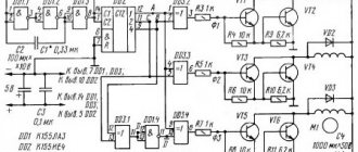
Based on the type of output signal, regulators are divided into stabilized and unstabilized. They can also be analog and digital (integrated). The first ones are built on the basis of thyristors or operational amplifiers. They are controlled by changing the parameters of the RC feedback chain. Together with them, bipolar or field-effect transistors are used to increase power. The operation of integrated devices involves the use of pulse-width modulation (PWM), so digital circuitry uses microcontrollers and power transistors operating in switching mode.
When making a homemade voltage regulator, the following elements can be used:
- resistors;
- thyristors or transistors;
- digital or analog integrated circuits.
The first two types have simple circuits and are quite easy to assemble yourself. They can be manufactured without the use of a printed circuit board using surface mounting, while switching regulators based on microcontrollers require more extensive knowledge in electronics and programming.
Signs of a faulty voltage regulator
A characteristic sign of a faulty voltage regulator relay is frequent discharge of the battery. This is explained by the fact that the energy storage device does not receive the necessary recharge from the generator while the engine is running. A faulty relay regulator should be suspected even if the battery is not completely discharged. For example, diagnostic signs such as dim headlights at night or an insufficiently powerful signal sound may indicate failure of this device.
The relay regulator may not supply voltage to the battery terminals or turn off on time. Such a breakdown will cause the battery to overcharge, which can lead to overheating of the internal battery plates and boiling off of the electrolyte.
Signs of a malfunctioning relay regulator may also include:
- Constantly lit battery light on the dashboard.
- The starter does not develop enough power to start the engine easily.
- Reduced engine power (can be especially noticeable at high speeds).
Even if there is one sign of failure, you should check the relay regulator for serviceability.
Reasons for failure of the relay regulator
Having an idea of the main symptoms of a faulty relay-regulator, as well as the reasons for the failure of this part, you can easily “diagnose” the chocolate bar in the generator without even carrying out additional diagnostic operations.
The most likely causes of failure of the relay regulator are:
- Short circuit in the wiring or generator windings.
- Failure of the generator diode bridge.
- Incorrect battery connection (reverse polarity).
- Mechanical damage.
The relay-regulator can also output when wet. As a rule, the device has a waterproof casing, and the elements inside can be filled with a special resin, but if the protection is damaged, moisture penetration will lead to failure of the electronic components of the regulator. An increased load on the device is also possible in the case when water gets on the generator winding while washing a car or when driving a car during heavy rain.
How to check the generator relay regulator on a car
You can check the generator integral without removing the device from the car. The diagnostic procedure can be performed either using special tools or simple methods that require the use of only simple instruments and devices.
How to test a relay for functionality without a tester
Diagnostics of the relay regulator using measuring equipment and additional devices will require significant costs if the necessary devices are not available. The cost of a new relay regulator is relatively low, and replacing the element requires a minimum amount of time. To make sure that problems in the vehicle's electrical system are caused by this device, it is enough to have a known good part on hand to perform a simple diagnostic operation.
It is not necessary to use a new relay regulator for this purpose. It is enough to check a used spare part in advance so that at any time and without the use of additional equipment you can accurately determine the reason for the non-standard operation of the vehicle’s electrical system.
Checking the generator voltage regulator with a multimeter without installation
Even an inexpensive multimeter or pointer tester can be successfully used to diagnose the generator relay-regulator directly on the car. You can check the device without dismantling it in the following sequence:
- Set the multimeter or tester to DC current measurement mode.
- Start the car engine.
- Measure the voltage at the battery terminals at an engine speed of no more than 1500 rpm (if the part is in good condition, the voltage will be in the range from 13.2 to 14.0 volts).
- Increase the crankshaft speed to 2500 rpm. Measure the voltage at the battery terminals (with the relay-regulator operating normally, the device should show 14.8 volts (an error of 0.2 volts is allowed)).
- Increase engine speed to 3500 rpm and measure the voltage again (should not exceed 14.8 volts if the regulator is working properly).
If, as a result of the measurements, all voltage indicators did not have significant deviations, then the relay-regulator is in good condition. Otherwise, you should purchase and install a new part.
How to check a combined type regulator
The operation of the relay regulator can be established using a simple test circuit, which consists of the following parts:
- DC source with a voltage of 12 V (you must use a device with the ability to adjust the voltage value, as well as with a built-in voltmeter).
- 12 V incandescent light bulbs (use a low-power light source of 3 - 4 W).
- Wires with crocodile fastenings.
Checking the relay regulator is carried out as follows:
- Connect the power source to the relay-regulator, observing the polarity.
- Connect the wires from the light bulb using “crocodiles” with graphite brushes.
- Set the voltage on the electrical device to 12.7 V. The light should be on.
- Increase the voltage to 14.5 V. The light should go out.
If the lighting element does not go out when the voltage reaches 14.5 V, then the regulator is faulty. In some vehicle models, the automatic device may be programmed to turn off when the voltage reaches 14.0 volts. This feature of the device is normal.
If the light bulb does not light up at normal voltage levels or goes out before the electrical device produces a voltage of 14.0 V, then the relay regulator will also need to be replaced.
If there is no source of electricity in the form of a regulated power supply, then you can use a battery and a step-up transformer with regulation.
Checking the voltage regulator of the VAZ 2107 generator
Checking the voltage regulator of the VAZ 2107 generator can be done according to the scheme described above. The principle of cutting off the electric current when a certain voltage level is reached also remains the same. The difference may only lie in the features of connecting the charging relay to the current source and the control lamp. Depending on the year of manufacture of the car, various types of devices may be installed on it. On machines produced before 1996, an old-style relay-regulator was located. Such a device is also diagnosed by connecting the operating voltage to the main terminals and a test light to the brushes. New cars use integral type products (chocolate). Such a device is connected in a similar way. The contacts that go to the generator brushes must be connected to the light bulb, and the other pair to the current source.
How to check a chocolate bar on a KAMAZ generator
The principle of operation of the Kamaz vehicle relay regulator is the same as on other vehicles. When a certain voltage value is exceeded, the regulation device cuts off the power supply to the battery terminals. You can qualitatively check the part using a variable voltage source and a test lamp. A special feature of testing the device is the use of a current source with an adjustable voltage from 20 to 30 volts; accordingly, the light bulb must be of the appropriate type (24 V). It is not recommended to use a high-power lighting element. It is enough to use an incandescent lamp installed in the turn signals.
The work of checking the “chocolate” of the Kamaz generator is carried out as follows:
- Remove the integral voltage regulator from the generator.
- Find 2 contacts of the product that connect to the brushes and connect an electric light bulb to them (the polarity does not matter; it is also recommended to use wires with crocodile clips).
- The “negative” wire of the power supply is connected to the “ground” of the chocolate bar.
- The “plus” of the power supply is connected to the second output of the regulator.
The principle of testing is similar to performing work on 12-volt devices. When a certain voltage level (about 27 volts) is reached, the charging current should be switched off. If this does not happen, the device should be replaced. If the control light does not light up, the chocolate bar should be discarded.
When performing diagnostics using an incandescent lamp, it is necessary to ensure that the electric light source is in good working order, otherwise incorrect results will be obtained from checking the relay regulator of a Kamaz vehicle.
How to check the integral on a generator
To test the integral on a passenger car generator, you can use a battery and an adjustable voltage transformer. You will also need to prepare a multimeter and an incandescent lamp for turn signals. The connection diagram for the generator integral will be as follows:
- An adjustable voltage transformer is connected to the battery.
- The integral is connected to the transformer.
- Wires from the light bulb are connected to the terminals of the integral.
- To monitor the voltage, a multimeter is connected to the circuit between the adjustable transformer and the integral, which should be switched to the constant voltage measurement mode.
The generator integral relay is checked using the following algorithm:
- By increasing the voltage through an adjustable transformer, they control the voltage level at which the light bulb will turn off.
- After turning off the lamp, the voltage is reduced and the moment when the lighting element is turned on is also set.
If the light bulb does not turn off, then the integral should be replaced. In a situation where a working lamp does not light up at all, the regulator must also be replaced.
When carrying out such a check, it is necessary to ensure the reliability of the contacts of the integral terminals with the connected conductors. If the contact elements are dirty, they should be cleaned using a wooden or plastic scraper, and to obtain high-quality contact, use crocodile-type connecting elements.
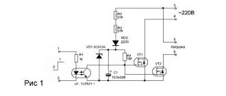
Scheme number 2
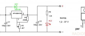
The new circuit also has a three-pin electrical connection. component (but this is no longer a transistor) constant and variable resistors, an LED with its own limiter. Only two electrolytic capacitors have been added. Typically, typical diagrams indicate the minimum values of C1 and C2 (C1=0.1 µF and C2=1 µF) which are necessary for stable operation of the stabilizer. In practice, capacitance values range from tens to hundreds of microfarads. The containers should be located as close to the chip as possible. For large capacities, the condition C1>>C2 is required. If the capacitance of the capacitor at the output exceeds the capacitance of the capacitor at the input, then a situation arises in which the output voltage exceeds the input, which leads to damage to the stabilizer microcircuit. To exclude it, install a protective diode VD1.
This scheme has completely different possibilities. Input voltage is from 5 to 40 volts, output voltage is 1.2 - 37 volts. Yes, there is an input-output voltage drop of approximately 3.5 volts, but there are no roses without thorns. But the KR142EN12A microcircuit, called a linear adjustable voltage stabilizer, has good protection against excess load current and short-term protection against short circuits at the output. Its operating temperature is up to + 70 degrees Celsius, works with an external voltage divider. Output load current is up to 1 A during long-term operation and 1.5 A during short-term operation. The maximum permissible power when operating without a heat sink is 1 W, if the microcircuit is installed on a radiator of sufficient size (100 cm2) then P max. = 10 W.
How to check a separate voltage regulator on a generator
Voltage regulators installed separately from the generator can be installed on older car models. Failure of such parts can also lead to overcharging or missing charge of the battery, so you should check it at the first suspicion of non-standard operation of this element.
Checking the generator voltage regulator relay type 591 3702 01
The principle of checking the regulator type 591 3702 01 is identical to other devices of this type. You will also need to connect the products to a DC source and, by changing the output voltage values on the power supply, set the moment when the control lamp turns off.
A design feature of the type 591 3702 01 regulator is the output part, which has contacts designated “67” and “15”. Contact “67” is the “minus” of the system, so the corresponding wire from the power source, which is connected in series with the incandescent lamp, should be connected to it. Also, the negative contact should be connected to the “ground” of the regulator (metal mount). Contact “15” is the plus of the device, so the positive conductor should be connected to it.
The device is checked according to the standard procedure. First, the operating voltage is applied at which the light bulb should light. When the maximum possible voltage (14.5 V) is exceeded, the electric current in the circuit disappears.
More precisely, the relay-regulator type 591 3702 01 can be checked on a special diagnostic stand. This installation has a generator, battery and voltmeter. The regulator is connected on the stand in the same way as when installed on a car. After starting the stand, adjusting the rotation of the generator ensures that the voltage exceeds the cut-off threshold (14.5 V). The device shutdown is recorded by a voltmeter.
If the relay regulator does not turn off the voltage supply when a critical level is reached or there is no electric current immediately after starting the generator, then you will need to replace the relay regulator type 591 3702 01.
How to check a three-level voltage regulator relay
Instead of a standard relay-regulator, a three-level relay can be installed on cars. Such devices are more advanced and reliable. The difference between three-level relays and “chocolate bars” is the ability to arbitrarily set the cutoff voltage using the built-in regulator.
Testing a three-level relay is carried out according to the standard scheme, when an adjustable source of electric current and a test lamp are connected to the relay. When performing the test, only the previously set cut-off voltage limits should be taken into account. That is, if, using manual adjustment, the shutdown moment was set at 14.7 V, then at this voltage the disappearance of the electric current will be the norm.
Generator check
If an overcharge of the battery can be caused by a malfunction of the relay-regulator, then if the battery is undercharged, the part may be completely serviceable. Various generator breakdowns can cause a permanent or temporary lack of electrical current to fully restore the battery. If the car has a separate relay-regulator, then this part can be easily excluded from the electrical circuit and thus ensure that the generator is working properly. The diagnostic operation is performed with the engine running as follows:
- Disconnect the wires from the relay regulator (pins 15 and 67).
- Instead of a relay regulator, a 12 V incandescent lamp should be connected to the circuit.
- Disconnect the positive cable from the battery while the engine is running.
If the engine continues to run when the positive terminal is disconnected, then the car’s generator is working. Otherwise, you should check this part and all additional elements involved in the transmission of electrical energy.
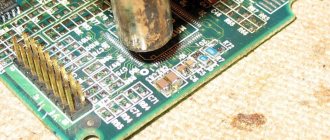
Features of the device and principle of operation
Generator type 37.3701 - alternating current, three-phase, with a built-in rectifier unit and an electronic voltage regulator, right-hand rotation (drive side), with a fan at the drive pulley and ventilation windows in the end part. To protect against dirt, the back cover of the generator is covered with a protective casing.
The operation of the generator is based on the effect of electromagnetic induction. If a coil, for example, made of copper wire, is penetrated by a magnetic flux, then when it changes, an alternating electrical voltage appears at the coil terminals. Such coils, placed in the grooves of the magnetic circuit (iron package), represent the stator windings - the most important stationary part of the generator - they are the ones that generate alternating electric current. The magnetic flux in the generator is created by the rotor. It also represents a coil (excitation winding) through which a direct current (excitation current) is passed. This winding is laid in the grooves of its magnetic core (pole system). The rotor, the most important moving part of the generator, also includes a shaft and slip rings. When the rotor rotates opposite the stator winding coils, the “north” and “south” poles of the rotor appear alternately, i.e., the direction of the magnetic flux penetrating the stator windings changes, which causes the appearance of alternating voltage in them. It would be possible to use a permanent magnet as a rotor, but the creation of magnetic flux by an electromagnet allows the generator output voltage to be easily adjusted over a wide range of rotation speeds and load current by varying the excitation current.
In order to obtain a constant voltage from an alternating voltage, six power semiconductor diodes are used, which together form a rectifier unit installed inside the generator housing.
The field winding is powered from the generator itself and is supplied to it through brushes and slip rings. To ensure the initial excitation of the generator, after turning on the ignition, current is supplied to terminal “B” of the voltage regulator through two circuits.
- Plus battery - contact 30 of the generator - contacts 30/1 and 15 of the ignition switch - contact 86 and 85 of the ignition relay winding - minus the battery. The relay turned on and the current flowed through the second circuit:
- Battery plus - contact 30 of the generator - contacts 30 and 87 of the ignition relay - fuse No. 2 in the fuse block - contact 4 of the white connector in the instrument cluster - 36 Ohm resistor in the instrument cluster - battery charging warning lamp - contact 12 of the white connector in the instrument cluster - contact 61 - terminal "B" of the voltage regulator - excitation winding - terminal "W" of the voltage regulator - output transistor of the voltage regulator - minus the battery.
After starting the engine, the excitation winding is powered from the common terminal of three additional diodes installed on the rectifier unit, and the voltage in the vehicle's electrical system is controlled by an LED or lamp in the instrument cluster. If the generator is working properly, after turning on the ignition, the LED or lamp should light up, and after starting the engine, it should go out. The voltage at the 30th pin and the common pin of 61 additional diodes becomes the same. Therefore, no current flows through the indicator lamp (LED) and it does not light up. If the lamp (LED) lights up after starting the engine, this means that the generator set is faulty, that is, it does not produce voltage at all, or it is lower than the battery voltage. In this case, the voltage at pin 61 is lower than the voltage at pin 30. Therefore, current flows in the circuit between them, passing through the LED/lamp. It/she lights up, warning that the generator is faulty.
Voltage regulator: purpose and principle of operation
The generator set is equipped with a semiconductor electronic voltage regulator built inside the generator. The voltage of a generator without a regulator depends on the rotation speed of its rotor, the magnetic flux created by the field winding, and, consequently, on the current strength in this winding and on the amount of current supplied by the generator to consumers. The higher the rotation speed and the excitation current, the greater the generator voltage; the greater the current of its load, the lower this voltage. The function of the voltage regulator is to stabilize the voltage when the rotation speed and load changes by controlling the excitation current.
Electronic regulators change the excitation current by turning on and off the excitation winding from the supply network (additional diodes). As the rotor speed increases, the generator voltage increases. When it begins to exceed the level of 13.5 ... 14.2 V, the output transistor in the voltage regulator is turned off and the current through the field winding is interrupted. The generator voltage drops, the transistor in the regulator unlocks and again passes current through the field winding. The higher the rotation speed of the generator rotor, the longer the time the transistor is in the locked state in the regulator, therefore, the more the generator voltage decreases. This process of locking and unlocking the regulator occurs at high frequency. Therefore, voltage fluctuations at the generator output are unnoticeable, and it can practically be considered constant, maintained at a level of 13.5...14.2 V.
Generator drive and mounting it to the engine
The generator is driven from the crankshaft by a belt drive using a V-belt. Accordingly, for this belt the generator drive pulley is made with one groove. To cool the generator, plates are spot welded on the back side of the pulley. On the pulley they are located almost perpendicularly and perform the function of a fan. The lower mounting of the generator on the engine is made on two mounting legs, articulated with the engine bracket with one long bolt and nut. The top one is through the pin to the tension bar.
Recommendations for increasing the service life of the regulator
If the faulty relay regulator is not detected in time, the battery may need to be replaced. Constant boiling of the electrolyte or complete discharge has a very negative impact on the performance of the battery. To minimize the negative impact of such situations, you should properly care for the elements of the vehicle’s electrical system to prevent the regulator from failing. The most effective preventive measures aimed at maintaining this part in working condition are:
- Regular cleaning of the generator. The presence of internal short circuits in the stator and rotor windings can be the main reason for the failure of the regulator, so regular maintenance of this part will significantly extend the life of the “chocolate” or a device installed separately in the engine compartment.
- Scheduled and unscheduled tightening of the generator belt. If there is even slight slippage of the belt, a significant decrease in the performance of the generator can be observed, therefore, at the slightest suspicion of weakening of this element, adjustment work should be performed immediately.
- Cleaning contact wires from oxidation. A high-quality supply of electric current from the generator to consumers will avoid power surges and failure of many devices, including the relay regulator.
Regular monitoring of the voltage at the battery terminals under different engine operating modes will allow you to timely determine the incorrect operation of the regulator relay. Detecting a breakdown at an early stage of problem development will allow you to avoid serious consequences.
Repair or replacement of the voltage regulator - what to choose
When various parts fail, the driver often makes a difficult decision: repair the part and install a new one. With a car relay regulator, such a dilemma arises only when using a car that was produced several decades ago. It is almost impossible to purchase new spare parts for rare car models, and disassembled parts may be of dubious quality. When an integrated device (chocolate bar) is used to adjust the battery charge level, such a device cannot be repaired. The parts installed in relay regulators of this type can be restored, but this work will require certain knowledge and skills, as well as significant time investment.
Replacing the generator relay regulator
If the relay regulator can no longer be used for its intended purpose, then a new part should be installed. The combined element changes in the following sequence:
- Disconnect the negative terminal of the battery.
- Disconnect the fasteners.
- Remove the brush assembly cover.
- Disconnect the diode bridge.
- Unscrew the contact group nuts.
- Unscrew the threaded elements holding the regulator.
- Remove the part.
Installation of a new regulator is carried out in the reverse order of removal. When performing this operation, the element contacts must be connected correctly.
Depending on the generator model, the process of replacing the relay regulator may differ slightly. The main thing is to perform dismantling, if possible, without damaging other elements of the generator set.
Replacing an individual element is much easier. For this purpose, it is enough to disconnect the main 2 contacts from the device, remove the product from the car body and install a new part in its place. Then correctly connect the previously removed wires and check the operation of the device. To do this, just start the engine and measure the voltage at the battery terminals at different speeds.
Voltage regulator repair
You can try to disassemble and repair old models of relay regulators that are installed separately. It should immediately be noted that such an activity has little promise, but if you ring the internal elements with a multimeter and find the burnt part, you can completely restore the functionality of the regulator.
Repairing the regulator relay can take too much time, so it is much easier and more correct to purchase a new product or remove the device from another car in which this part is in known good condition.
To find out whether a car relay-regulator is working correctly or not, it is enough to carry out simple diagnostics using a multimeter or a test lamp. If the device being tested does not show signs of life, then it is enough to change the part to restore the functionality of the electrical system. Repairing a “chocolate” or “tablet” is practically impossible, but other types of regulators can also be restored with great difficulty. Therefore, if the battery is not charging or too much voltage is supplied to the battery, you need to purchase a new product from a specialized store.
Stories from our readers
“Fucking basin. "
Hi all! My name is Mikhail, now I’ll tell you a story about how I managed to exchange my two-wheeler for a 2010 Camry. It all started with the fact that I began to be wildly irritated by the breakdowns of the two-wheeler, it seemed like nothing serious was broken, but damn it, there were so many little things that really started to irritate me. This is where the idea arose that it was time to change the car to a foreign car. The choice fell on the melting Camry of the tenth years.
Yes, I had matured morally, but financially I just couldn’t handle it. I’ll say right away that I am against loans and taking a car, especially not a new one, on credit is unreasonable. My salary is 24k a month, so collecting 600-700 thousand is almost impossible for me. I started looking for different ways to make money on the Internet. You can’t imagine how many scams there are, what I haven’t tried: sports betting, network marketing, and even the volcano casino, where I successfully lost about 10 thousand ((The only direction in which it seemed to me that I could make money was currency trading on the stock exchange, they call it Forex. But when I started delving into it, I realized that it was very difficult for me. I continued to dig further and came across binary options. The essence is the same as in Forex, but it’s much easier to understand. I started reading forums, studying trading strategies. I tried it on a demo account, then opened a real account. To be honest, I didn’t manage to start earning money right away, until I understood all the mechanics of options, I lost about 3,000 rubles, but as it turned out, it was a precious experience. Now I earn 5-7 thousand rubles a day. I managed to get the car buy after half a year, but in my opinion this is a good result, and it’s not about the car, my life has changed, I naturally quit my job, I have more free time for myself and my family. You’ll laugh, but I work directly on the phone)) If If you want to change your life like me, then here’s what I advise you to do right now: 1. Register on the site 2. Practice on a Demo account (it’s free). 3. As soon as you get something on the Demo account, top up your REAL ACCOUNT and go to REAL MONEY! I also advise you to download the application to your phone, it’s much more convenient to work from your phone. Download here.
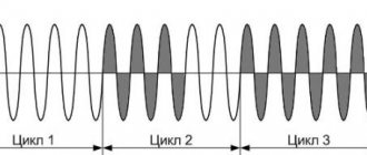
2. MAX - both diodes are used 3. MID - only diode D2 is used. In such a scheme, any switching is painless - in intermediate states of the toggle switch there will be mode No. 2.
I connected the red wire to the “In” terminal, and the black wire to the “Out” terminal.
- When toggle switch S1 is in position “1” , the generator operates in normal mode.
- In position “3” of toggle switch S1, one Schottky diode is connected. The voltage at the generator output increases by 0.3-0.4V.
- When toggle switch S1 is in position “2” , two Schottky diodes connected in series are connected to the generator circuit. The generator output voltage increases by (0.3-0.4V)*2.
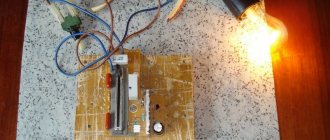
The arrangement of parts in the case and the fastening of the metal strip on the case cover are shown.
To connect the box with diodes to the generator, I had to remove the plastic cover. I ran the wires through the slot in the generator cover.
- I soldered the male terminal to the red wire. It connects to the wire with the “mother” coming from the additional diodes of the diode bridge.
- I soldered the “mother” terminal to the black wire with the wire sealed at 90 degrees. This wire connects directly to the excitation terminal of the voltage regulator.
Having connected these wires to the generator circuit, we put the plastic cover in place and connect the standard wires going to the gene. This is what it looks like assembled:
Next, we screw the plastic box with diodes to the car body between the adsorber and the right headlight. To make it look better, we put plastic on the wire and lay it along the standard wiring and secure it with clamps.