Along with motor protection circuit breakers and thermal relays, modern motors use temperature sensors based on thermistors and posistors to protect against overheating.
Unlike traditional methods, for example the same thermal relays, where protection of asynchronous motors from overload is carried out based on the thermal effect of the current heating the bimetallic plate of the relay, thermistor protection responds directly to the temperature of the motor windings.
Protection using thermal relays, motor circuit breakers, is indirect thermal protection, since it does not interact directly with the motor windings. That is, it responds not to the actual heating temperature of the stator windings, but to the amount of heat generated, without taking into account the operating time in the overload zone and the actual cooling conditions of the engine.
In certain cases, such protection may not be effective enough, since it does not allow the actual heating temperature of the electric motor to be determined with sufficient accuracy. This applies, in particular, to electric motors with a long start-up period, frequent on-off switching, etc.
In the case of protection based on PTC sensors, the degree of heating of the stator windings is controlled directly, since the sensors are built into the windings, that is, they have direct contact with it.
Thanks to this, the motor is protected from overload, asymmetry and phase failure, insufficient cooling, since all these reasons one way or another lead to heating of the windings, and consequently to the operation of the sensors.
Another important feature of this type of protection is that the operation depends only on the temperature of the engine and does not depend on the load on the engine itself.
Thermistor sensors do not protect the electric motor in the event of a short circuit or insulation breakdown.
Temperature sensors
Temperature sensors are among the most commonly used sensors. Temperature sensors are used by all types of equipment, ranging from computers, cars, kitchen appliances, air conditioners and (of course) home thermostats. The five most common types of temperature sensors include:
- thermistors;
- thermocouples;
- RTD (resistive temperature sensors);
- digital thermometer chips;
- analog thermometer microcircuits.
This article will provide you with a brief introduction to each of the sensor types listed.
Technical specifications
A wide variety of thermal resistance models are dictated by the needs of the modern electronics industry. The technical parameters of semiconductor-type products make it possible to fully satisfy the demand of manufacturers of radio-electronic and electrical devices.
The main parameters include:
Semiconductor thermistors have high sensitivity in combination with negative TCR values. They are easy to manufacture, have tiny sizes, and are easily integrated into microcircuits. All these properties make thermistors indispensable in microelectronics.
Semiconductor thermistors are connected via a bridge circuit. This connection allows you to automatically adjust the required parameters of electrical circuits. Sometimes for these purposes it is necessary to use rather complex automation schemes.
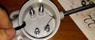
The parameters of metal thermistors are more suitable for electrical devices, in particular, they are used as temperature sensors. They can be seen in water heating systems, or in resistance thermometers. These types of sensors (Fig. 7) are very reliable in operation and have a fairly wide measurement range.
Rice. 7. Temperature sensor
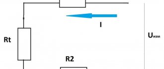
Sensors of this type are connected according to a simple scheme. If calibration or temperature adjustment is required, this is usually done manually using a potentiometer. A simple diagram of connecting a temperature sensor is shown in Fig. 8. By changing the voltage with a potentiometer, you can influence the TCR value. You can visually control the temperature using an ammeter, the scale of which is graduated in degrees.
Rice. 8. Simple diagram for connecting a thermistor
Thermistor
As the name suggests, a thermistor (i.e., thermistor) is a temperature sensor whose resistance varies with temperature.
Thermistors are available in two types: PTC (positive temperature coefficient) and NTC (negative temperature coefficient). The resistance of a PTC thermistor increases with increasing temperature. An NTC thermistor, on the other hand, decreases in resistance as temperature increases, and this type appears to be the most commonly used type of thermistor. See Figure 1 below.
Figure 1 – Graphic symbols of PTC and NTC thermistors
It is important to understand that the relationship between a thermistor's resistance and its temperature is very nonlinear. See Figure 2 below.
Figure 2 – Dependence of NTC thermistor resistance on temperature
The standard formula for NTC thermistor resistance versus temperature is given by:
\[R_T=R_{25C}\cdot e^{\left\{\beta\left[\left(1/\left(T+273\right)\right)-\left(1/298\right)\ right]\right\}}\]
Where
- R25C is the nominal resistance of the thermistor at room temperature (25°C). This value is usually given in the technical description;
- β (beta) is the thermistor material constant in Kelvin. This value is usually specified in the technical description;
- T is the actual temperature of the thermistor in Celsius.
However, there are two simple methods used to linearize the behavior of a thermistor, namely resistance mode and voltage mode.
Resistance linearization mode
In resistance linearization mode, a conventional resistor is placed parallel to the thermistor. If the resistor value is equal to the thermistor resistance at room temperature, the linearization region will be symmetrical about the room temperature point. See Figure 3 below.
Figure 3 – Resistance linearization mode
Voltage linearization mode
In voltage linearization mode, the thermistor is placed in series with a conventional resistor, thereby forming a voltage divider. This voltage divider must be connected to a known, fixed, stabilized voltage reference VREF.
This configuration results in an output voltage that varies relatively linearly with temperature. And, as in the temperature linearization mode, if the resistance of the resistor is equal to the resistance of the thermistor at room temperature, then the linearization region will be symmetrical about the room temperature point. See Figure 4 below.
Figure 4 – Voltage linearization mode
Design
The simplest thermistor consists of a temperature-sensitive element, platinum electrodes and nickel leads. This entire structure is enclosed in a sealed housing (the structure diagram is shown in Figure 2).
Metal oxides are used as heat-sensitive materials. To protect the structure, a glass, plastic or metal case is used.
Rice. 2. Design of a simple thermistor
In some cases, copper or platinum is used as the resistive material. These materials have high TCR values for metals in the operating temperature range. However, their use is limited due to the high cost of platinum and its nonlinear transformation.
The use of copper thermistors is limited by the low corrosion resistance of copper. Due to the high thermal conductivity of this metal, copper-based resistive elements are found in models with indirect heating. Suitable for temperatures not exceeding 180 ºC.
Another disadvantage of metal thermal resistances is their inertia, which can reach several minutes. Such designs are not very suitable for maintaining the thermal regime of electrical appliances, but they are ideal as sensors for measuring temperature.
In order to reduce thermal inertia, thermistors are made of microwires, which are enclosed in a glass bulb (see Fig. 3). Such sensors are well sealed, stable, and their inertia does not exceed fractions of seconds.
Figure 3. Thermistor design in a glass bulb
Types of sensors based on semiconductor materials have become widespread. When semiconductors are heated, these materials become saturated with electrons and holes, which leads to a decrease in resistance.
There are designs of flat thermistors (Fig. 4), as well as semiconductor thermistors with a complex structure of the resistive element.
Thermocouple
Thermocouples are typically used to measure higher temperatures and wider temperature ranges.
To summarize how thermocouples work: any conductor subjected to a temperature gradient will generate a small voltage. This phenomenon is known as the Seebeck effect. The amount of voltage generated depends on the type of metal. Practical applications of the Seebeck effect use two dissimilar metals that are joined at one end and separated at the other. The connection temperature can be determined by the voltage at the open ends of the wires.
There are different types of thermocouples. Certain combinations have become popular and the choice of combination depends on various factors including cost, availability, chemical properties and stability. Different types are best suited for different applications and are usually selected based on the required temperature range and sensitivity.
For graphs of thermocouple characteristics, see Figure 5 below.
Figure 5 – Characteristics of thermocouples
PTC resistors (PTC resistors) as a type of thermistors
For electronics, temperature is one of the factors that requires constant monitoring, since abnormal heating indicates a change in current parameters and unsafe phenomena (overheating up to burnout).
On instrument boards, the most basic standard elements, radio components that measure t°, monitoring its values and protecting the circuit, are thermistors. The parts react in a special way: their resistance (R) changes at different temperatures, and accordingly, currents of a certain power are passed or not passed, this is how the protection of the microcircuit and devices is realized.
Thermal resistors (TR) are semiconductor electronic parts made from alloys with a high thermal transformation coefficient.
Resistive temperature sensors (RTDs)
RTDs, also known as RTDs, are perhaps the easiest temperature sensors to understand. RTDs are similar to thermistors because their resistance changes with temperature. However, instead of using a special material that is sensitive to changes in temperature (as in thermistors), RTDs use a coil of wire wrapped around a ceramic or glass core.
The wire in an RTD is made of a pure material, typically platinum, nickel or copper, and this material has a precise resistance-temperature relationship that is used to determine the temperature being measured.
Application
Thermistors are mainly used to protect equipment and various devices from overheating and possible overloads. Less often, the dependence of the resistance stabilizes the operation of the heating element.
Examples of using:
Most circuits use the ability of thermistors to convert internal energy into an electrical signal that is read by automation.
In heating devices, a thermistor is quite often used as a self-resetting fuse. Its resistance increases when a critical temperature is reached and, as a result, the electrical circuit opens.
After cooling, the device restores functionality. The areas of application can be listed for a very long time, but these examples also show how popular thermistors and thermistors have turned out to be.
Analog thermometer microcircuits
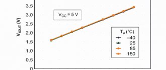
Instead of using a thermistor with a fixed resistor in the voltage divider, an alternative solution is an analog low temperature sensor such as the TMP36 from Analog Devices. Unlike a thermistor, this analog IC provides an output voltage that is nearly linear; The slope is 10 mV/°C over a temperature range of -40 to +125°C, and its accuracy is ±2°C. See Figure 6 below.
Figure 6 – Graph of TMP36 output voltage versus temperature from the technical description
Although these devices are extremely easy to use, they are significantly more expensive than a thermistor-plus-resistor combination.
PTC resistors (PTC resistors) as a type of thermistors
For electronics, temperature is one of the factors that requires constant monitoring, since abnormal heating indicates a change in current parameters and unsafe phenomena (overheating up to burnout).
On instrument boards, the most basic standard elements, radio components that measure t°, monitoring its values and protecting the circuit, are thermistors. The parts react in a special way: their resistance (R) changes at different temperatures, and accordingly, currents of a certain power are passed or not passed, this is how the protection of the microcircuit and devices is realized.
Thermal resistors (TR) are semiconductor electronic parts made from alloys with a high thermal transformation coefficient.
Digital thermometer chips
Digital temperature sensors are more complex, but they can be very accurate. Additionally, they can simplify overall development since the analog-to-digital conversion occurs within the thermometer chip rather than in a separate device such as a microcontroller. For example, the DS18B20 from Maxim Integrated has an accuracy of ±0.5°C and a temperature range of -55°C to +125°C.
Additionally, some digital ICs can be configured to be powered from the data line, allowing them to be connected with only two wires (i.e. data/power and ground). You can read more about the “single-wire” interface here.
Figure 7 – Block diagram of DS18B20 from the technical description
How to connect, diagrams
Let's look at the basic connection diagrams for a PTC resistor, depending on the purpose for which it is used. Most often, the elements are connected in series, but sometimes they can also be connected in parallel, for example, to a start relay.
Scheme for thermal fire detectors:
PTC as fuse:
Examples of other circuits for posistors:
As a temperature sensor, temperature compensation
Below is the principle of temperature compensation: when biasing the transistor, R of the posistor is used. If the first one overheats, the t° on the second one also increases, and when the value overcomes the Curie point, the TR switches to the powerful resistance mode, the circuit shifts, and the transistor turns off.
If the PTC acts as an overheat detector when temperature compensation is required, the device does not change the input resistance like an NTC thermistor, given the series connection to the input circuit. This is excellent for variants of the latter that require the described nuance: for impulse lines, regional amplifiers, measuring devices.
Several posistors in the circuit
Two or more PTCs can serve several active segments of the comparator. Below is a diagram for sequentially connecting an increased number of TRs: when at least one of the microcircuits is detected by the comparator, a sharp value of temperature resistance is demonstrated. Such a circuit will allow you to easily change the number of PTCs or measure t° on the entire basic circuit.
Engine overheat protection
PTC is used to monitor overheating of electric motors, transformer windings, bearing structures, and power transistors. Below is an example of a PTC that detects excessive heating of the motor, which triggers the relay to turn it off.
Directly with a posistor, circuits with small regular currents can be blocked, but if they are large and constant, a relay or thyristor can be connected to the line.
Control Component
PTC, as an electronic component of current control, is shown in the simplest solution below:
When the set temperature is exceeded, the diode lights up. If the current limit value is violated, the thermistor will react and immediately implement protection.
The delay option can be implemented through the dynamic properties of the TP, there are two methods: connecting in parallel or in series with a relay. It is also possible to control starting currents with a posistor, for example, on switching power supplies, which, as a rule, have a significant value at the first start.
PTC can be used instead of NTC or a simple resistor as an inrush current limiter. The part is heated by current overloads when a relay or thyristor fails and it is triggered at high resistance, the flow of current is blocked instantly.
In addition to the above, it is practical to use PTC for a motor starting circuit as a contactless starter, for example, for a compressor for refrigerators, air conditioners and the like.
On Arduino
A programmable base in the form of an Arduino controller is used for various homemade products and mini-robots.
In this case, it is necessary to connect the PTC to the specified platform to read the indicators, an LCD display showing them will also be included there.
Description of the example (with a thermistor rating when it is hot at 10 kOhm):
- there is a ceramic heating part of the soldering iron with low-resistance PTC, how to connect it to Arduino;
- This is the solution. The order of the circuit is: “ground - PTC - resistor of about 10 kOhm - +5V (positive contact). That is, from the PTC connection with the resistor, pull the wire to the Arduino input. If the latter is analog, then with cold PTC there is about 0, with hot 500 Ohms, if digital, then LOW and HIGH. If you need to configure exactly when to turn it on. HIGH, experiment with a resistor - the higher its value, the later (with a hotter TR) this value turns on.
Below is the same thing in slightly different words. For a basic assembly, let's take a circuit board, 3 wires, PTC, a 10 kOhm resistor (this is the main resistance of the circuit). The output of the latter is connected to the PTC pin, to which there is also a wire connected to, in our case, the analog pin A0 of the Arduino. That is, one PTC contact is to 5V, and the second, connected to the leg of the 10 kOhm resistor, is to A0. The remaining leg of the latter goes to the ground pin. The diagram below shows the order clearly.
You can learn more about working with various components on some online simulator.
Comparison of temperature sensor types
The table below shows a comparison of the different types of temperature sensors discussed in this article.
However, keep in mind that this information should be taken as a generalization. The table is intended primarily for those who do not have much experience and/or knowledge about temperature sensors. Table 1. Brief comparison of temperature sensors
| Sensor type | Typical Temperature Range (°C) | Accuracy (+/- °C) | Advantages | Flaws | Application |
| Thermistor |
| 1 |
|
| Ambient temperature measurement |
| Thermocouple | -200° to 1450° | 2 |
|
| Industrial use |
| RTD | -260° to 850° | 1 |
|
| Industrial use |
| Analog chip | -40° to 125° (TMP36) | 2 |
|
|
|
| Digital chip | -55° to 125° (DS18B20) | 0,5 |
|
|
|
Original article:
- Nick Davis. Introduction to Temperature Sensors: Thermistors, Thermocouples, RTDs, and Thermometer ICs
How PTC works from a physico-chemical point of view
A PTC thermistor increases its resistance (denoted in diagrams by R, in Ohms) as t° increases; The NTC thermistor has the same algorithm, but vice versa: as the first value increases, the second value decreases.
The main feature of the thermistor is the maximum sensitivity R of the material to changes in t°. If there is no heating, then the atoms are arranged evenly, arranged in long lines. As heat increases, the number of charge transporters becomes larger, and the more, the better the conductivity.
The t°/R curve is nonlinear; the properties are most pronounced at −90…+130° C.
TR properties are created by comparing the t° mode with the characteristics of the alloys used in the part, which are semiconductors. They use compounds that are extremely temperature sensitive.
When current passes, an electric field appears, pushing the electrons hitting the atoms, so they are slowed down. At high temperatures, the movement of atoms is more intense, the initial particle interacts faster, creating additional resistance. After cooling, the valence levels of electrons will become low, go into a quiet state, the particles will move less, and will no longer increase the Ohm number.
Graphic designation
In UGO thermistor diagrams, the thermistors may differ slightly, but the main sign of thermal resistance is the symbol t next to the rectangle symbolizing the resistor. Without this symbol, it is impossible to determine what the resistance depends on - for example, varistors have similar UGO (resistance is determined by the applied voltage) and other elements.
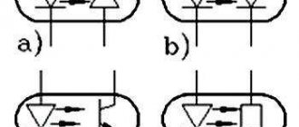
Sometimes an additional designation is applied to the UGO, which determines the category of the thermistor:
- NTC for elements with negative TCS;
- PTC for posistors.
This characteristic is sometimes indicated by arrows:
- unidirectional for PTC;
- multi-directional for NTC.
The letter designation can be different - R, RK, TH, etc.