December 14, 2018
telecommunicationssecurity systemspower managementmedicinecritical applicationsTexas Instrumentsarticleintegrated circuitsdevelopment tools and materials
Programmable logic controllers are already 50 years old, but it is still impossible to imagine automated production . We are starting to publish a series of articles about PLCs and electronic components produced by Texas Instruments to create modern PLCs .
Subscribe to receive notifications when new articles about PLC are published.
Programmable logic controllers (PLCs) are widely used in the field of industrial automation of various technological processes in large and small enterprises. The popularity of controllers is easy to explain. Their use greatly simplifies the creation and operation of both complex automated systems and individual devices, including household ones. PLC allows you to shorten the development stage, simplifies the installation and debugging process due to the standardization of individual hardware and software components, and also provides increased reliability during operation, convenient repair and modernization if necessary.
It is generally accepted that the task of creating a prototype of a modern PLC arose in the late 60s of the last century. In particular, in 1968 it was formulated by executives from General Motors . Then this company was trying to find a replacement for a complex relay control system. According to the design assignment received, the new control system had to meet the following criteria:
- simple and convenient creation of technological programs;
- the ability to change the working control program without interfering with the system itself;
- simple and inexpensive maintenance;
- increased reliability at reduced cost compared to similar relay systems.
Subsequent developments at General Motors, Allen-Bradley , and other companies led to the creation of a microcontroller-based control system that analyzed input signals from process sensors and controlled electric actuators.
The term PLC (Programmable Logic Controller, PLC) was subsequently defined in the EN 61131 (IEC 61131) standards. A PLC is a unified digital control electronic system specifically designed for use in industrial environments. The PLC continuously monitors the status of the input devices and makes decisions based on the user program to control the status of the output devices.
A simplified representation of the composition and operating principle of the PLC is well demonstrated in Figure 1. It can be seen that the PLC has three main sections:
- entrance;
- day off;
- central.
Rice. 1. Composition and principle of operation of the PLC
There is also a power source. It is possible to connect an external PC to the PLC for programming and debugging.
The central section contains the central processing unit (CPU), memory and communications system. It processes the data received from the input data section and transmits the processing results to the output section. It should be immediately noted that in large PLCs, in addition to the CPU operating in the “master” mode, there may be additional “slave” PLCs with their own CPUs. Standard microprocessors (MPs) are used as the CPU of a small PLC. Typically, 8- and 16-bit MPs cope well with all standard tasks. But, as noted in IEC 61131, the choice of a specific MP still depends on the tasks assigned to this type of PLC.
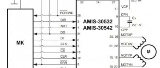
To transfer data to another PLC or to connect to PROFIBUS, Industrial Ethernet, AS-Interface data networks, distributed control systems today use communication processors such as the DP83867IR from Texas Instruments (TI).
The PLC input section provides input to the central section for the status of switches, sensors, and smart devices. Through the output section, the CPU controls external actuators, which may include electromagnetic motor starters, light sources, valves and smart devices.
general information
Beginner users often wonder what programming logic controllers is. In fact, the programming language of these devices is identical to the operating logic of conventional relays. Therefore, specialists who have previously worked with relay circuits will easily understand the creation of programs for PLCs.
Signal wiring and standard programming development may vary between brands and models of PLCs, but in general terms they will still have a similar set of features and features. Therefore, we can consider general principles.
First you need to understand the device itself:
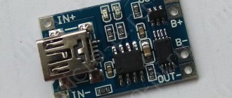
- a simple industrial logic controller on the front includes 2 screw terminals L1 and L2, which are responsible for connecting the internal circuits of the device;
- On the left there are 6 screw terminals, which are necessary for connecting input devices. They represent 6 input channels;
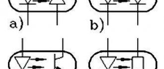
- An opto-isolator is located in the housing to provide an electrically isolated signal to the PC circuit when communication is established between the input terminal and the common terminal. The LED at the input displays the situation, which of the inputs is currently energized;
- The output signals are obtained by the controller circuitry by activating the switching device. This allows you to link a source terminal to a user-labeled Y output.
Thus, PLC programming is based on determining which outputs are energized and what input conditions are present. All programs are developed using a PC, which is connected to the controller's programming port.
Special systems are used to program industrial controllers. There are 2 possible options for this:
- The PLC manufacturer offers its own software environment, which is implemented to work from a specific developer. They are distributed both paid and free, depending on the company and model;
- Software development companies create custom programming systems for PLCs from different manufacturers.
CS-CS.Net: Laboratory of the Electroshaman
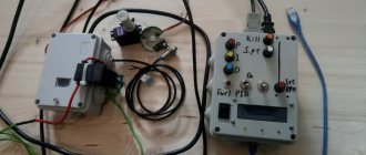
Test stand for ARIES PLC 110
Well? I continue to cover the basic concepts of PLCs and how to program them. Today I will tell you about my further adventures with ARIES and how I programmed it. As I said before, PLC programming is a whole different religion! This is not for you to move circuits or cubes in a logical relay! Here everything is much wiser and the correct choice of hardware, the correct physical connection of IO lines and external modules are very important.
For PLCs, there are usually two options for development environments: CodeSys and proprietary. CodeSys is a free development environment that is divided into a compiler and a kernel. PLC manufacturers load the CodeSys kernel into it during production. And all that is needed to program such a PLC is to download CodeSys and special files that describe a specific PLC model.
The second option is your own kernel and your own development environment. Here every manufacturer is perverted as he pleases. I wanted to tinker with Siemens, but they told me that their development environment requires a very powerful computer and consumes a lot of resources. I don’t like this, and I’d rather choose something that works with CodeSys, because it’s easier for me to install a good environment once, lick its settings and just do programming.
The PLC that the customer bought for his shield runs on the CodeSys v2 kernel. Now the CodeSys v3 kernel is used everywhere, and the second version of the kernel is outdated. But since the principles of programming are still the same, this post will be useful to all beginners. Yes, and I want to share the information that I collected bit by bit, having been surrounded by documentation for a week. Crap! It seems to me that I already need to either teach training courses or sell posts, gee =)
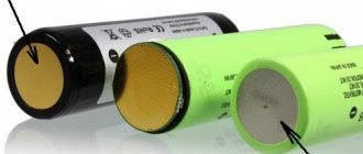
The first thing programming work begins with is creating a test bench. I had DIN rail buttons from ABB lying around, and I assembled four input lines from them: three on the on-board IO PLC, and one on the external module in order to check how polling of modules via ModBus works.
Buttons for sending signals to PLC inputs
Configuring external modules and ModBus
I have a large post about the ARIES Mx110 and Mx210 modules. Read it - there is a lot of interesting stuff there!
The first thing our programming begins with is the hardware configuration. Any external module has its own address on the RS-485 bus. The module also needs to specify the correct exchange settings: speed, parity and type of exchange protocol.
Each module or external device is configured differently. Someone will need to go into the menu and change the numbers there. Someone need to install jumpers. And other devices have a special configurator program to configure them. This is exactly how ARIES does it.
Their modules are connected standardly via RS-485 to a computer and are configured using a program. In order to connect RS-485 to a computer, you will need any interface converter. There are plenty of them on the market and you can use any of them. If you want, you can even wrap RS-485 in regular Ethernet and communicate with modules or our system over the grid.
Since ARIES was around me, I bought an ARIES AC-4 . They have it in a DIN rail housing, powered by the USB port itself. One of the features is that you can use jumpers to connect and change the resistance of RS-485 bus terminator resistors.
We supply power to the module and connect it to the converter:
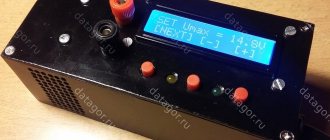
ARIES AC-4 converter and IO module setup
Next, we launch the “M110 Configurator” program. First of all, the program will prompt us to set the settings for connecting to the module. If we just bought a module, then we can safely press the “Factory network settings” button. And if the module is already configured for a certain address and other protocol parameters, then we need to know them in advance and enter them into the program:
Connecting to the IO module in the program
If for some reason we have forgotten all the module settings (for example, we were given a BUSH module), then we can start scanning the network. The program will find everything it can and offer to connect to the specified module. Well, if we can’t do anything at all, then the I/O module itself can be hard reset to factory settings by installing one of the jumpers that are located on it under the cover. This is described in the instructions for the module.
After we have connected to the module, the program gives us all its settings, which can be read and written to the module. We are interested in network settings: communication speed, network address and all sorts of timeouts. Let me remind you that the modules have a trick: if it has not been polled via RS-485 for the specified time, then it considers that the connection has been broken and sets emergency values at the outputs so that the equipment does not do anything wrong (the elevator itself does not move or the pumps do not turn on, etc.). In our case, the module controls the light bulbs, so we set all alarm values to zero.
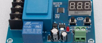
Settings of the MU110-16R relay output module
And some I/O modules can also communicate using different protocols. And even ModBus itself has a couple of modifications: RTU (devices exchange binary data) and ASCII (all data is sent in text form). We will use the faster ModBus-RTU protocol.
Settings for the MV110-16D input module
Please note that there is a software contact bounce filter for input modules. We include it too.
This program also has the ability to monitor the state of inputs and outputs. Using this, you can separately test each module for functionality.
Learning CodeSys
So, using the program, we configured all modules with the same communication parameters and gave them addresses. Now they can be physically connected to the PLC, and the PLC itself can be plugged into the grid. The ARIES 110 PLC can be programmed in three ways: via USB, via RS-232 and via grid. The best way to do this is to program the PLC on the grid, because in this case it does not restart, but the program is hot-loaded there. That is, they wrote it, uploaded it, checked it. Did they fix anything? Immediately downloaded and checked. If you program the PLC via USB, then you have to remove the USB cable after uploading the program, which is hellishly inconvenient.
Communication with PLC 110 via Ethernet
And now we begin to understand CodeSys. I downloaded it directly from the ARIES website, where it is available in Russian. In general, I don’t like Russian translations of special software, because it is translated by those who don’t understand a damn thing about technology. For example, AutoCad had the most hellish translation: “Cut, Trim, Stretch, Dismember, Explode.” Or P-CAD, where Net (connection) was translated as “Network”. But in the case of CodeSys, the Russian translation helped me understand the terminology and where everything is located. After this, I no longer need a Russian translation, and I can navigate the English environment freely.
The environment itself consists of a project tree, with several tabs and tree elements. They display both the program structure and all sorts of evil parameters of the PLC and its external resources. All elements of the tree are opened by a bunch of child windows with their own settings.
CodeSys v2 development environment for PLC 110
CodeSys itself supports many programming languages. Including those on which it is convenient to program logical relays.
Example of a CodeSys project in several languages simultaneously
For example, you can program using block diagrams (CFC). It’s like we were taught at school to draw algorithms in the style of “Start => Data input => If .. then => otherwise => End.” Here it is drawn using blocks:
Example of sequential logic circuits (CFC)
Or you can program it using functional blocks (FBD), like on logical relays. In this case, the circuit is not executed sequentially as in CFC, but according to signals, as in conventional digital logic on microcircuits:
Example of Function Block Development (FBD)
For those who are switching from conventional relays and automation, it is possible to write everything in relay logic LD, LAD. Then all signals are described by contacts that turn the relay on or off:
Ladder Diagram (LD) Design Example
There is also an instruction language called IL. It is suitable for those who love harsh assembler. Look how similar he is to him:
Example of development in instruction language (IL)
And in my opinion, the most convenient language for complex tasks is plain text ST, which looks like a mixture of SI and Pascal at the same time:
Example of development using the code editor (ST)
Here you have both comments and the opportunity to write any conditions.
Inside CodeSys you can combine all these languages and create your own functional blocks. For example, you can write a complex block in ST that calculates something and produces a logical value of 1 or 0 at the output. And then take the FBD language and create a “simple” logic circuit from these blocks.
Distributing PLC resources
Our programming, of course, is closely related to hardware. And our CodeSys environment must know what hardware we are currently using. This is, of course, understandable: different PLCs have different amounts of memory, I/O ports and other gizmos.
Therefore, a new project always begins with choosing a platform. In English it is called Target. The environment itself will never know about any ARIES and other PLCs. Initially, she only knows about a certain abstract kernel “3S CodeSys”. For her to find out about our PLCs, we need to go to the developer’s website and download Target files for our PLCs from there.
After this, the Targets are loaded into CodeSys (on version 2 this process is hellishly murky, unobvious and disgusting), and we can finally create. Select the desired version of our PLC:
Choosing hardware for developing a program for a PLC
Now we immediately remember that a PLC is a multitasking system, within which tasks revolve - programs that do something. There may be several tasks, but at least one is needed for the PLC to work. In CodeSys it must be called “PLC_PROG”, and this is what we are immediately offered to create after selecting the PLC platform.
Immediately when creating it, you need to select the language in which you will write the code. If you suddenly make a mistake with the name of the language (I constantly confuse IL and ST), then you can simply delete this task and create a new one with the same name.
Creating a default main program
After that, our project was created and the environment left us behind. If we write in ST, then in the PLC_PROG code it is enough to put “;” and the program will compile. But nothing will work. Why? But because the PLC does not know how to access its resources and what it even has.
And in order to teach it this, you need to carefully and carefully understand its resources and how to register external I/O modules there. All this seems easy only when you understand everything yourself. And when you look at the PLC configuration for the very first time, it makes your head explode. I dealt with this for about five days, because the instructions for working with CodeSys on the ARIES website say “Do this and that,” but do not say WHY you need to do this. I want to correct this shortcoming and then I will send ARIES a link to these posts.
In order for CodeSys to know about all the resources and input-output of the entire PLC-based system, all this must be written manually. That is, the entire system configuration is hard-coded in the same program code. And therefore, when you select all sorts of I/O modules, assign communication parameters and addresses to them, you must understand that this will remain forever. And if you need to change the device address, then you will need to recompile the project.
The general concept of resources and access to them is made using certain addresses. These addresses are calculated by the environment itself based on our PLC configuration. In the screenshot below, these addresses begin with the signs “AT%”. So that the programmer does not have to worry about these addresses, he can create ordinary program variables that will use friendly names like “WaterPump” instead of addresses, which will actually talk about an external output at an address like “%QW6.3.0.0”.
Therefore, our first task will be to study the “PLC Configuration” window and what can be done there. Let's take a look at it:
Configuration of the PLC and its resources
On the left we have a tree in which the entire configuration of our system will be shown. And to the right of the tree there are different parameters that can be configured. There you can also set clear names and names for all system objects for yourself, so as not to get confused.
On the left I now have the configuration of the PLC itself expanded. What do we have here? There are two fast entrances, 16 regular entrances (18 in total). There are also four fast outputs and 10 regular outputs - a total of 14. This corresponds to what this PLC actually has. Additionally, there is a Special Input - this is the “F1” button on the PLC itself and a Special Output - this is the PLC beeper. If we write “1” there, the beeper will beep and draw our attention to the system.
These resources are labeled "[FIX]" or "[SLOT]". If “SLOT” is written, this means that the software can force the environment to perceive these inputs or outputs not as discrete 1..0, but for example as an encoder or PWM controller. This is done in order to facilitate programming by forcing the PLC to process data from IO as automatically as possible, without burdening the programmer with this. Accordingly, those resources that “FIX” cannot be changed and they will always be what they are.
Next to each resource, its address is indicated where it can be accessed. Now, if we want to programmatically enable fast output 2, then we need the address “%QX2.0”. I'll talk about how to assign addresses to variables later.
Each resource has its own set of settings. For example, you can configure safe values for outputs in the same way as for external I/O modules:
Setting safe values for PLC outputs
Go ahead! It was we who studied the internal resources that are on board the PLC. How can we get to external resources? Here we have as many as three input/output modules. But where are they?
And nowhere! They must be added manually. The logic here is simple and technical: what you physically have should also be in the program. Let's remember what we have physically? Modules? Nope! We have ModBus protocol!
Therefore, we click on the PLC itself and select this very ModBus (Master) from the menu like this, as shown below. Master - because we have the main PLC in our network, and it is he who will control all other modules. There are also other exchange protocols for different network options. For example, you could even take your own “ARIES” protocol and build a grid on it.
Adding an external communication interface
Please note that this protocol is not currently tied to the physical PLC wires! After we add our ModBus, the system will simply know that there is some abstract protocol by which the bytes are sent. But she doesn’t know yet which PLC port it will work through!
What to do? We will have to teach our system the required port. To do this, we expand the tree under our ModBus and see what we are looking for. By default, the system substituted the very first available PLC interface - “Debug RS-232”. We see the magical inscription “SLOT” next to it. Right-click on it and voila! We can replace it with the one we need on RS-485.
Selecting the RS-485 interface type
Moreover, the replacement list will only include those options that are actually available in this particular PLC. For example, some PLCs have as many as two RS-485 interfaces, on which two different ModBus networks can be built.
And only now we have reached the physical level: RS-485 itself. For it we have settings for the exchange protocol and communication parameters. If you remember, we configured all modules for ModBus RTU and baud rate 9600. Now let’s insert the same settings in our PLC:
Configuring interface protocol parameters
The PLC itself monitors the operation of this protocol and this interface. We do not need to programmatically enable or disable polling of modules: it will be done automatically if there is at least one external module that needs to be polled.
Now we will just add our external modules. ARIES himself recommends adding your modules as “Unversal ModBus Device” - some kind of abstract device. Let's do this:
Adding a ModBus device
Now we have a certain external module that is connected to our RS-485 bus and will work via ModBus. But let me remind you that the ModBus protocol is simply a way to read and write bytes to and from devices. And nothing more. But what each byte means and the memory area where it needs to be written/read is known to the module developer and the developer of the PLC-based system.
For each module you will need to set communication parameters. For us, this is the module address (ModuleSlaveAddress) and the time it is polled by the controller. The controller will automatically communicate with the module once every milliseconds we specify.
Configuring device parameters
The polling time reduces the load on the communication bus. For example, if a module controls lighting bulbs, then it can be polled less frequently, giving bus time to some faster analog control modules.
Well, we added a module, so what? How does the system know how to control its inputs or outputs? In general, how does she know where he has them? And she finds out through a person who takes out and reads the instructions for the module. For any device with the ModBus protocol, the manufacturer provides a table that shows all the addresses of its registers. This table looks like this, for example:
Example of device registers from the documentation
Here we are interested in two points. Since this is an input module, we need to receive the values of its inputs. The manufacturer, in order not to send tons of bytes across the network, packed all 16 inputs into 16 bits - into two bytes, into the WORD type. This means that we are interested in register number 51, which will need to be read from the module. The next point that is important to us is to check the command that is used to write and read data into this module. Sometimes they may differ from the standard ones.
Great! Now we know everything to add it to our PLC. We click on the menu on our module and choose what to add. Types in CodeSys are called like this:
- 8 Bit - BYTE, byte
- Register - INT, WORD - two bytes
- 32 Bit - DWORD, four bytes
Since the documentation shows that we are reading a two-byte word, we need the “Register input” type:
Adding a device register to the configuration
Now we set the parameters specifically for this piece: the address of the register that we are reading and the command that we are reading with.
Configuring the register address and the method for polling it
Now (see screenshot above) the PLC knows that we have a MoBus-RTU protocol based on the RS-485 interface, on which a device with address “1” hangs, from which we read two bytes from cell “51”.
And here is what the PLC configuration looks like for my system. I have one input module with 16 inputs and an output module with 16 outputs. And for the future, there is an analog output module for dimming the light.
Complete list of external devices and external registers
Assigning Variables in a PLC
Now we have all the addresses of our resources. To make it convenient for us to use them, we will create program variables for them. This is also manual work that requires care. It’s also not very convenient to do it in CodeSys v2, because the width of the columns in the table for entering variables does not change.
Let's look at the PLC configuration and grab from there the addresses of all our inputs and outputs. I've highlighted them in red:
Addresses of internal I/O variables
Now let's create variables for them. To do this, we go to the “Global Variables” section and start filling out the table something like this:
Creating internal I/O variables
Do you see? We indicate the name of the variable and write down its address and type. And now to enable internal output 1, we need to write “MOuts0_1 := TRUE;”.
Let's do the same with external devices. Here the addresses become longer:
External I/O variable addresses
And editing them is not very convenient. Filling in the variables:
Creating external I/O variables
In addition to variables that beautifully connect resource addresses and code, you can create your own variables for any task. All these variables will be global: they will be accessible from anywhere in any program.
Well, if we now upload this empty program (we didn’t write anything in the code) into the PLC, it will immediately begin polling our modules. In the photo below, I accidentally captured the moment when the PLC interrogates one of the modules.
After startup, the PLC begins to poll all external devices
Programming
And then the witchcraft begins. At that time I needed to learn how to work with CodeSys. Then I couldn’t figure out whether it was possible to address individual bits of variables and wrote simple sections of code that brought all the variables of external resources into code that was understandable for me.
You see, I simply take the bit value of the variable I need (from the input) and put it in a global variable, which already designates a specific light control button.
Code for converting input variables to BOOL type
I did the same with the outputs:
Code for converting output variables from type BOOL
Now you can code. For the test, I did the simplest thing: press the button - the output is triggered. That is, we simply assign the output to the input and enjoy the work of a powerful PLC 
A piece of firmware for lighting control on a PLC
I also found on the Internet an example of how to make a pulse relay on CodeSys and also tested it. By the way, an example is on the ARIES forum.
It's not very pleasant for them on the forum. Cunning comrades hang out there (not from ARIES), who in a personal message immediately offer each new user services for the development and support of PLC solutions. One of them wrote to me too. Just for fun, I told him to fuck off and asked why he did it. The answer was typically marketing: “Well, if you’ve registered here, then you can be my client.” As a result, the comrade was sent far and long. Especially after he started threatening to shut down my blog for telling me to fuck you. Hmmm. It’s scary, in general, on the ARIES forum.
Tasks
I’ll briefly show you what the tasks are and what you can do with them. Let me remind you: a task is a piece of a program that the PLC will execute after a specified time. There are system events which are shown below (PLC start, PLC stop, before and after reset):
Setting up tasks in the PLC
And we want to assign our own tasks to the PLC. Here I got two of them. One counts pulses from water meters, and the other serves lighting control.
For each task, its execution time is specified. It can be measured in milliseconds, hours and even days.
Task configuration in PLC
Well, for the task itself, what will be executed is specified:
Setting up a subroutine call in a task
Communication with PLC and uploading the program
Well, now all we have to do is upload our program to the PLC. To do this, we go to the “Online -> Communication Settings” menu and create a mesh connection there via the TCP protocol.
Setting up communication with the PLC via IP protocol
After this, just select the command to connect to the PLC:
We begin connecting to the PLC
CodeSys communicates with the PLC and asks us what we need to do with the program. If the PLC is only from the factory and there is no program there, then CodeSys will offer to load a new program into the PLC. And if there was already a program in the PLC, the system will offer to load a new one or rewrite the program completely:
The development environment requests that the program be loaded into the PLC
With PLCs, everything here is different from logical relays. In a logic relay, the program is loaded forever and will run after turning the relay power off and on. But with a PLC, the program is simply loaded into memory and works only when the PLC power is turned off. This was done on purpose so that you can debug the program and not spoil the working system and program. For example, you can play around with a different version of the program, and then turn off the power supply - and the PLC will work as before.
If we want to write our program to the PLC forever (so that it will work the next time the power is turned on), then we need to select the “Create boot project” item. In this case, the program without requests is written to the PLC and will be executed the next time it is turned on.
Creating a boot project in the PLC
Among the additional features, you can load project sources or any file (several megabytes in size) into the PLC. This is useful if we want to keep an archive of documentation for the entire project inside the PLC.
When connected to the PLC, you can observe how and what it works and debug the program. This is what it looks like on ours:
Operation of the CodeSys environment in program debugging mode
Actually everything about programming. To put it all concisely, in order to start working with a PLC, you need to add all its resources and external modules to it. After this, you can assign variables to addresses and write regular program code.
Libraries
There are also many libraries with ready-made functions for CodeSys. The most famous among them is the OSCAT library. I downloaded it and found a lot of interesting things there. For example, here is the CLICK module, which can detect single, double and triple clicks on a button. Using it, you can do it, for example, so that if we turn off all the lights with one button, then when we double-click on it, all the lights turn on in the same place where they were turned on.
Example from the OSCAT library: Determining the number of clicks
But here is a sophisticated dimmer with a bunch of presets and capabilities. The signal from the dimmer can be sent to an analog output module or to a dimmer that is controlled via Modbus directly and controls the lighting.
Example from the OSCAT library: Multifunctional dimmer
Well, I made for the customer a simple program for turning the lights on and off and implementing the leakage protection function. I will talk about this later in the third part of the article.
Siemens programming
Siemens PLC programming may be needed in the following cases:
- occurs in combination with an automation cabinet; it is used to control various automation systems of different purposes and types;
- creating a user interface for devices with displays or simultaneously connected to the operator panel;
- development of programs for processing, archiving and storage, as well as outputting final readings with internal calculations of the PLC itself and from external devices;
- to organize the interaction of the controller with SCADA format systems;
- implementation as part of large-scale automation systems, where several PLCs are connected to the circuit at once;
- implementation of functionality for interaction in special Slave and Master modes with industrial equipment via communication protocols.
Programming of Siemens controllers is carried out in certain environments. One of them is TIA Portal, which is designed for organizing automation systems of various levels of complexity and includes a certain set of software components: Simatic Step 7, WinCC, PLCSIM. Functional:
- development of configuration and debugging of system components;
- creation and adjustment of communication networks;
- software development for controllers;
- organization of Simatic operator panels and implementation of HMI (human-machine interface).
For example, programming of Siemens Logo controllers is carried out, as in the classical general case, after installation and configuration of the device. In this case, in simple words, the process is the input of a switching circuit. Let's list the main stages:
- first, using the standard diagram from the manual, you should understand the location of the connecting elements: inputs and outputs;
- Next you need to understand the blocks and their numbers. Blocks are functions that are responsible for converting input data into output information. Therefore, it is necessary to connect the connecting elements by selecting the required connection from the Co menu. The simplest blocks are logical operations. When a block is inserted into a program, the first one is assigned a specific number, which is subsequently used to display connections between blocks;
- The creation of a circuit occurs by connecting blocks with connecting elements. The process itself begins with an output, which is either a relay or a load, due to which control occurs. At this stage, you need to connect switches S1-S3 to the screw terminals;
- After designing the circuit, it is necessary to enter and launch the program. To do this, the Siemens Logo PLC is connected to the network and the power is turned on. Then the logic controller switches to programming mode, where the desired program is organized based on the previous circuit.
Types of PLC
Modern PLCs using innovative technologies have moved far from the first simplified implementations of an industrial controller, but the universal principles embedded in the control system have been standardized and are successfully developing on the basis of the latest technologies.
The world's largest PLC manufacturers today are Siemens AG, Allen-Bradley, Rockwell Automation, Schneider Electric, Omron . In addition to them, PLCs are produced by many other manufacturers, including Russian companies KONTAR LLC, Aries, Segnetix, Fastwel Group, Tekon group of companies and others.
Rice. 2. Monoblock programmable logic controllers
Based on their design, PLCs are divided into monoblock (Figure 2) and modular. A monoblock PLC housing houses a fixed set of inputs/outputs along with the CPU, memory and power supply. Modular PLCs use separately installed I/O modules. According to the requirements of IEC 61131, their type and quantity can vary depending on the task at hand and be updated over time. PLCs of this concept are shown in Figure 3. Such PLCs can operate in “master” mode and be expanded by “slave” PLCs via an Ethernet interface.
Rice. 3. Programmable logic controllers with advanced capabilities
Monoblock functionally complete PLCs may include a small display and control buttons. The display is designed to display current operating parameters and operating programs and technological settings entered using command buttons. More complex PLCs are combined from individual functional modules that are mounted together on a standard mounting rail. Depending on the number of serviced inputs and outputs, the required number of input and output modules is installed.
The power source can be built into the main PLC unit, but more often it is made in the form of a separate power supply unit (PSU), mounted nearby on a standard rail. A low power power supply is shown in Figure 4.
Rice. 4. Power supply for PLC
The primary source for the power supply is most often an industrial network 24/48/110/220/400 V, 50 Hz. Other power supply models can use a 24/48/125 V DC voltage source as a primary source. Standard power supply voltages for industrial equipment and PLCs are: 12, 24 and 48 V. In high-reliability systems, it is possible to install two special redundant power supplies to duplicate the power supply .
To save information during emergency power outages, the PLC uses an additional battery.
As is known, the initial concept of a programmable logic controller was formed during the transition from relay-transistor control systems for industrial equipment to microcontrollers that appeared then. Similar PLCs with 8- and 16-bit MPs of limited performance are still in successful use and are finding new areas of application.
Enormous progress in the development of microelectronics has affected the entire PLC element base. Their range of functionality has expanded significantly. A few years ago, analog processing, process visualization, or even separate use of CPU resources as a direct control device were unthinkable. Support for these functions is now included in the basic version of many PLCs.
An example of such an approach is a separate direction in the Texas Instruments product line. As you know, TI is not one of the PLC manufacturers, but produces specialized CPUs and network processors for them, components for creating peripheral digital and analog modules, temperature controllers, and mixed digital and analog input/output modules.
The block diagram of the TI Sitara AM570x processor in Figure 5 allows us to judge the enormous functionality of this ARM processor, operating at frequencies up to 1 GHz, supporting CAN, I²C, McASP, McSPI, SPI, UART, USB interfaces and capable of operating in a temperature range of 0... 90°C.
Rice. 5. Block diagram of the TI Sitara AM570x processor
Aries PLC Programming
Aries PLC programming is carried out in IEC 61131-3 languages. Among them, IL, FBD, LD, SFC, ST are used. As mentioned above, for this, environments from the manufacturer (the most suitable option) or third-party software are used. If we are talking about Aries products, then the choice falls on CoDeSys.
The specified programming environment for Aries controllers helps to design a suitable program, as well as debug it and load it into the PLC. To use CoDeSys, the user must take care of the runtime environment provided by the manufacturer or created by the developer himself.
In addition, programming of Aries controllers can be done using the MasterSCADA enterprise dispatch tool, which can act as a suitable environment for the development and implementation of the desired program. The advantage of this option is the ability to combine a whole variety of PLCs that operate on different systems.
PLC software
A modern PLC has a developed set of software, consisting of PLC system software provided by the controller manufacturer and third-party or proprietary software designed for developing, debugging and writing user programs to the controller.
The PLC system software, consisting of an operating system with a set of drivers integrated into it, is responsible for the execution of the user application by the controller, serves the low-level input-output system of the controller, data transfer interfaces, controls memory allocation, power consumption modes, timers, and performs error handling, allowing the user Developing an application, concentrate entirely on the algorithmic part of solving the application problem.
Tools for developing and debugging user programs allow you to create and adjust programs that implement controller operation algorithms, simulate on a PC the process of program execution by the controller, observe intermediate results of calculations, and also write software to the controller.
Delta PLC
Delta PLC programming is carried out using a special WPLSoft package, which does not require a large amount of personal computer resources. Therefore, it is suitable for use by specialists of various categories and is very simple. There are 3 languages used here: LD, SFC and IL.
The main feature of the process here is the creation of step diagrams, which ultimately make up the overall program. The process is carried out line by line. This factor greatly simplifies software development for PLC Delta.
Technical task
Creation and approval of technical specifications (TOR) is a very important part of software development. How effectively the development will be carried out depends on a well-written technical specification.
Experienced programmers know that a program is not written in one go. As a rule, the software is adjusted and approaches the final version through iterations in accordance with the wishes of designers, engineers, electricians, mechanics and technologists. Therefore, it is very important at the stage of drawing up the technical specifications to closely interact with all interested specialists who sign the technical specifications and upon completion accept the work.
Schneider Electric
Schneider Electric PLC programming can be performed using one of several environments: EcoStruxure Machine Expert, EcoStruxure Machine Expert HVAC, Unity Pro, Zelio Soft. Creating programs is used for the same purposes as Siemens brand controllers. The following types of automation systems are most often designed to control technological processes:
- ventilation equipment;
- air conditioning systems;
- individual heating points;
- lighting systems;
- control of conveyor lines and machines;
- water treatment;
- Packaging equipment;
- lifting machines and related mechanisms.
Requirements, limitations and challenges in PLC design and manufacturing
Thus, it becomes clear that a PLC is simply a specially designed digital control system based on processors of different powers and with different functional equipment, depending on its purpose. Such a system can also be considered a specialized mini-computer. Moreover, it is initially aimed at operation in the workshops of industrial enterprises, where there are many sources of electromagnetic interference, and the temperature can be both positive and negative. In addition to minimizing the impact of the above factors, it is necessary to provide protection from an aggressive external environment, including dust, splashes of process fluids and air-steam mist. In such cases, it is possible to install the PLC in protective cabinets or in remote areas. Individual modules can be located up to hundreds of meters away from the main PLC package and operated in extreme ambient temperatures. According to IEC 61131, the permissible temperature for outdoor PLCs is 5...55°C. For a PLC installed in closed cabinets, it is necessary to provide an operating range of 5...40°C at a relative humidity of 10...95% (without condensation).
The type of PLC is selected when designing the control system and depends on the assigned tasks and production conditions. In some cases, this may be a monoblock PLC with limited functions and having a sufficient number of inputs and outputs. Other applications will require a PLC with advanced capabilities to allow for a distributed configuration with remote I/O modules and remote process controls.
Communication between remote units and the main PLC core is carried out through noise-resistant field buses over copper cables and optical communication lines. In some cases, for example, to communicate with moving objects, wireless technologies are used, most often these are Wi-Fi networks and channels. To interact with other PLCs, both the well-known RS-232 and RS-485 interfaces and more noise-resistant industrial options such as Profibus and CAN can be used.
Mitsubishi PLC
Mitsubishi PLC programming is organized using the new generation GX Works2 environment. Supports the following languages: IL, LD, SFC, LD, FBD, ST. The environment comes in two types: GX Works2 and GX Works2 FX. The second is for setting up FX series controllers:
Functionality of the programming environment for Mitsubishi PLC:
- parameterization of functional modules;
- use of software libraries and special functional blocks;
- simulation is built into the system for offline verification of configuration and programs;
- a wide range of functions for diagnostics and debugging;
- the ability to restore previous versions of programs and compare them with current ones;
- compatibility with a number of GX Developer projects.
How PLC works
Before using a PLC, it must be loaded with system software and a user program designed to solve a specific application problem. All PLC software is typically located in non-volatile memory and is protected from damage in the event of a power reset. Changing the application program code in the PLC memory can be done multiple times by the user.
A typical PLC operating diagram can be described as follows.
Sensors are connected to the external input channels of the controller, and actuators are connected to the output channels. Power is supplied to the controller and its system software begins cyclically executing the user application.
The application execution cycle consists of the following sequential stages:
- The controller system software reads the state of each input channel of the controller and writes it to the internal memory of the controller;
- The controller system software, sequentially, command by command, executes the entire user application: each executable command of the application reads the data it needs from the internal memory, performs calculations with them and writes the results of its calculations to the internal memory of the controller;
- The controller's system software receives from the internal memory those values that need to be displayed at the controller output and transfers the output channels to the appropriate state, after which the entire execution cycle is repeated from the beginning.
The considered approach to the architecture of the user program execution environment makes it possible to implement logically parallel execution of several tasks by the controller within one user program, allowing you to automate the control of several simultaneously occurring processes using a single PLC.