Features of regulators for primary transformers
The battery charging current is 10% of its capacity. This means that a battery with a capacity of 60Ah is charged with a current of no more than 6A. The charging voltage when the car is running is 14.5V. Given the required margin, the charger should be capable of delivering 10A at 16V.
A voltage reserve is necessary to regulate and limit the charging current.
In different models of devices it is done in different ways:
- Additional resistances. They turn on after the diode bridge. The simplest design, but with the largest dimensions.
- Transistors. High adjustment accuracy, but the most complex circuit that requires good cooling of power transistors.
- Thyristor control. Simple diagrams. The adjustment is carried out by a thyristor switch in the primary winding circuit or by thyristors installed instead of diodes in the rectifier bridge.
DIY memory assembly
Now we can talk about the thyristor charger. This circuit can be used to assemble a charger suitable for servicing a car battery.
In general, nowadays there is access to a large number of different electronic circuits. There are both complex and simple ones. Complex circuit diagrams contain all the necessary adjustments, a high level of protection, and an impressive set of components. But such circuits are expensive, and making a thyristor charger out of them for your car’s battery is not particularly profitable.
VD1 and VD2 - bridge rectifiers; VS1 - thyristor; R1, R2, R3 and R4 are resistors; C1 - capacitor; R5 - potentiometer; DA1 - microcircuit.
In most cases, when planning to assemble a battery charger using thyristors with their own hands, craftsmen use simple circuits. Such devices include several inexpensive elements. Moreover, some of them can be taken from old computers and other equipment that are no longer suitable for use.
If you are also interested in circuits for thyristor chargers to charge the battery, you need to study the entire assembly process in more detail.
We will consider almost the simplest regulator, based on a thyristor, but allowing you to charge the battery without any problems.
The process is divided into several stages:
- choosing a suitable scheme;
- selection of the necessary components;
- calculation of parameters;
- assembly.
Next, about each stage separately.
Diagram and purpose of a thyristor voltage regulator for a transformer
The current flowing through the battery during charging is determined by the internal resistance of the battery, its emf and the voltage at the output of the charger. To change it, in addition to other methods, you can adjust the voltage on the primary winding. The most convenient way is to use a thyristor regulator.
Battery charging models
Chargers are divided into three groups:
- Launchers. Designed to start the engine with a discharged battery. It is not recommended to use it to charge batteries - insufficient voltage and lack of adjustments.
- Chargers. Designed to charge batteries. They have manual or automatic adjustment.
- Starting chargers. Can perform both functions.
Operating principle of a thyristor regulator
A thyristor has two states - open, in which it passes electric current, and closed. This element opens when current flows through the control electrode and remains open as long as current flows through the thyristor. The alternating voltage in the network has a sinusoidal shape. A thyristor connected to the load circuit opens at a certain moment of the half-wave. This is called the “opening angle”. As a result, current does not flow through the electrical device all the time, but only after the element has transitioned to the open state. This changes the effective voltage across the load.
Important! A voltmeter measures the RMS value. For reliable operation, the permissible voltage of the thyristors must correspond to the maximum voltage, which is 1.4 times greater. For a household network this is 308V.
ZPA with battery discharge function
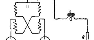
Proper operation of batteries in substations and power plants includes not only proper charging, but also periodic discharge of the battery. A complete battery discharge is, in fact, the only absolutely reliable way to determine the actual battery capacity. In addition, by periodically completely discharging the battery and then fully charging it, the natural aging process of the battery slows down. This is especially important for batteries that are constantly in maintenance charge mode. Therefore, many BDBA designs are equipped with a set of powerful resistors designed to discharge the battery with a controlled current. The most advanced models discharge the battery to the supply network, that is, they return the energy accumulated by the battery to the network (this process is called “recovery”). The main difference between these models and the simple BPA described above is the presence of additional contactors in the output circuit (Fig. 8), which ensure a change in the polarity of the battery connection to the BPA when switching it to discharge mode, as well as the presence of an additional controller (Fig. 9), which ensures synchronization with the network and sequential control of each thyristor according to a special algorithm.
Rice. 8. Fragment of the circuit diagram of the power section of the BDBA with additional contactors K1 and K2, which serve to switch from battery charge mode to discharge mode
Thyristors, as is known, cannot independently go into a non-conducting state (lock up) when a direct current flowing through them exceeds a certain very small value of the holding current. However, in the BD circuit in battery discharge mode, turning on a particular thyristor results in the application of a reverse voltage to the thyristor through which the battery discharge current is currently flowing, as a result of which this conducting thyristor is turned off and goes into a non-conducting state. Thus, by alternating the unlocking of some locked thyristors in a certain sequence, it is possible to simultaneously lock other open thyristors. As a result, the thyristor circuit generates rectangular current pulses of opposite polarity (meander), which, after passing through the inductances of the chokes and windings of the power transformer (operating in this mode as if in the “reverse direction”), take the form of a sinusoid and in this form enter the network.
Rice. 9. Controller type SIMATIC S7-200 (Siemens), used in the ELCO automatic control system to control the process of discharging the battery to the mains supply
Considering that the process of discharging the battery must be carried out with a constant current, it becomes clear that it is not easy to provide the required algorithm for the operation of the BPA; this requires a separate controller. In the most modern BDBA models with microprocessor control, separate controllers are no longer required.
Types and technical characteristics of thyristor regulator
Due to the fact that the thyristor passes voltage of only one polarity through itself, it cannot be used to control a transformer without additional elements:
- Connect the thyristor to a diode bridge of 4 diodes at the “+” and “-“ terminals. The “~” pins are connected to the open circuit instead of the switch or in series with it. The diode bridge rectifies the voltage and the thyristor is supplied with power of only one polarity.
- Use two thyristors connected back-to-back and for control the control outputs are connected through a variable resistor. Each element opens at its own polarity, and both together control the voltage across the load.
The opening of the thyristor occurs when a current exceeds a certain value and there are two ways to control the opening angle:
- Variable resistance connected between the anode and the control electrode. During the first half of the half-wave, the voltage and control current increase and when it reaches a certain value, depending on the brand of the element. The disadvantage of this circuit is the limited adjustment range of 110-220V, but this is enough to control the charger transformer.
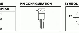
- Control of pulses that are supplied by a separate circuit to the control electrode at a certain moment of the half-wave of a sine wave. The permissible current and voltage of the thyristor regulator depend primarily on the installed thyristors. The most common are thyristors of the KU 202 series, but in some cases the use of other elements is allowed:
- KU 202N – 400V, 30A. Mounted on M6 thread. When adjusting the primary winding, the current of which is less than 1A, they are used without radiators.
- KU 201l - 300V, 30A, fastening - M6 thread. Can be used in the primary winding.
- KU 201a – 25V, 30A, fastening – M6 thread. Can only be used with radiators when adjusted after the transformer.
- KU 101g – 80V, 1A. Looks like a transistor. They are not used in power circuits of chargers, only in control circuits.
- KU 104a – 6B, 3A. Also not used in power circuits.
Build process
Since the diagrams can be modified, plus each master sees the assembly process differently, it is difficult to describe detailed instructions here. But still, a few main points are worth highlighting. Namely:
- first, the board on which the thyristor charger will be based is printed;
- all components are installed and soldered;
- then the mounting holes are drilled;
- case components and a measuring device are selected to monitor the charging process;
- diodes and radiators are connected;
- a thyristor is installed;
- everything is well insulated;
- the front panel is made;
- wires are supplied and connected;
- final assembly of all remaining elements is performed.
All that remains is to test the resulting charger.
Yes, it may look unsightly in appearance, especially if there is no body as such. But it’s all a matter of your desire and capabilities.
Anyone who wants can go crazy and make a really beautiful case that is in no way inferior to factory chargers.
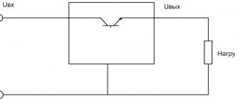
What is a triac
The thyristor has a drawback that complicates its use in an alternating current network - it passes through only one half-wave and the output produces a constant pulsating voltage instead of an alternating voltage. Therefore, these devices are used in pairs or together with a diode bridge. The triac is free from this drawback.
A triac is similar in appearance to a thyristor. Just like a thyristor, it opens with a current pulse flowing through the control electrode, but this device passes both half-waves through itself and is capable of operating in an alternating current network.
Schematic diagram of a triac current regulator for active and inductive loads. The design of a triac regulator is similar to a thyristor regulator. The difference is that the triac controls both polarities and therefore there is no need to use a diode bridge or back-to-back connection of elements.
In addition, the polarity of the control voltage does not matter for the triac, which simplifies the pulse control circuit.
Advice! To adjust the triac, you can use a dimmer from an incandescent lamp. To do this, it is connected between the anode and the control electrode of the power triac.
How does such a device work?
The characteristics described below will correspond to most circuits.
In this case, there is a certain area that will be under special stress. When the effect of the positive half-wave ends and a new period of movement with a negative half-wave begins, one of these thyristors will begin to close, and at the same time a new thyristor will open.
Instead of the words positive and negative wave, you should use the first and second (half-wave).
The principle of operation of the second circuit will be exactly the same, but it will control only one of the half-waves of alternating current. After the user understands the principle of operation of the device and its general structure, he will be able to understand how to assemble or, if necessary, repair the thyristor power regulator himself.
Other simple options for adjusting the voltage in the primary
In addition to thyristor and triac regulators, there are other ways to control the charging current in the primary winding of a transformer:
- Switching the leads of the primary winding. The disadvantage is that these conclusions must be made when winding the coils.
- By connecting the charger after LATRA (laboratory autotransformer). Its power must be at least 160W.
- Variable resistance connected in series with the transformer. Its parameters are approximately 50-100 Ohm, power 50 W and depend on the specific charger.
Despite the advent of modern chargers, many car owners have devices with conventional transformers, and adjusting the device along the primary winding makes it possible to do without powerful thyristors or additional resistances.
Some results
Concluding the consideration of various types of BDZ, it should be noted that their most common type are devices based on a three-phase thyristor adjustable rectifier. Portable light-duty ZPAs are made with a high-frequency link. The most reliable and durable are the ferroresonant type BDBAs, but they are also the heaviest.
Literature
- Guidelines for the design of operational direct current systems (OCDC) of the UNEG substation. STO 56947007-29.120.40.093-2011.
- Bogdanov D.I. Ferroresonance voltage stabilizers. M.: Energy, 1972.