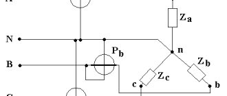
The “star” phase connection diagram for power receivers has become very widespread in the power industry. The star connection diagram is shown below:
It is clear from the diagram that the phase voltages of the receiver Ua, Ub, Uc are not equal to the line voltages Uab, Ubc, Uca. If we apply Kirchhoff’s second law to the circuits aNba, bNcb, cNac, we obtain the relationship for phase and line voltages:
If the resistance of the neutral wire and linear wires is not taken into account, then it can be assumed that the voltage at the terminals of the generator and the power receiver are equal. Due to this equality, the vector diagrams for the source and receiver of electrical energy will be the same.
The phase and line voltages of the receiver, as well as the source, will form two symmetrical voltage systems. Accordingly, there will be a certain relationship between the phase and linear voltage values:
It will be shown below that relation (2) will be valid only under certain conditions, as well as in the absence of a neutral wire, that is, in a three-wire network.
Based on the above relationship (2), we can conclude that it is better to use a star connection in the case where each phase of a three-phase power receiver or single-phase receivers are designed for a voltage several times less than the rated line voltage of the network.
Also, from the star connection diagram (see diagram above) it is clear that when connecting the receivers with a star, the phase currents will be equal to the linear ones:
By applying Kirchhoff's first law, we can obtain the relationship between currents when connecting electrical receivers with a star:
Knowing the phase currents using formula (4), you can calculate the neutral wire current IN. In the absence of a neutral wire, the following expression will be valid:
Star connection of a three-phase generator
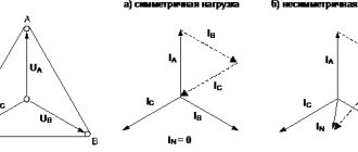
Let us place on the drawing images of three windings ax, by and cz of a three-phase generator at angles of 120°, as was done in Figure 1, a. Let's connect a load to each winding. In this case, these are resistances za, zb and zc. In practice, the load can be lamps, furnaces, electric motors and other electrical receivers. Six wires were required to connect the generator windings to the loads. At any given time, three of them are direct - the current through them goes from the generator to the load. The other three wires are return.
Vectors Ea, Eb and Ec are located parallel to the windings and represent their electromotive forces (emf). Voltages Ua, Ub and Uc are less than the corresponding e. d.s. by the magnitude of the voltage drop in the windings. The directions of currents Ia, Ib and Ic are depicted by arrows.
Combining three return wires into one gives a four-wire circuit (Figure 1, b). In it, the wires connected to the generator terminals a, b and c are called linear (or simply phases). The common wire is called either neutral on the grounds that it equally belongs to any phase, or zero , since in some cases the current I0 in it is equal to zero.
Naturally, the question arises: can the current in the wire through which the three phase currents must return to the generator be equal to zero? The answer is given in Figure 1, c, where the vectors depict the currents Ia, Ib and Ic (the sum of which forms the current I0) and their addition is performed. First, the currents of two phases are added, then their sum is added with the current of the third phase. As a result, zero is obtained, since geometric sum of the currents of the two phases, which is clearly visible in Figure 1, c, is equal in magnitude to the current of the third phase b and is directed directly opposite.
Figure 1. Star connection of a three-phase generator.
The physical meaning of the result obtained is that, due to the phase shift between the currents, at each moment of time, the currents in some linear wires go from the generator, in others - to the generator. In other words, some of them are direct, others are inverse. The role of linear wires as direct and return wires, of course, is constantly changing, but one way or another, with a uniform (identical) phase load, there is no current left for the neutral wire.
With a uniform load of phases, the neutral wire is not made, thus obtaining a three-wire circuit (Figure 1, d).
With an uneven load in a four-wire circuit, only an imbalance of currents flows along the neutral wire. Therefore, the cross-section of the neutral wire is not larger than the cross-section of the linear wires, but, as a rule, half as much. The issue of the cross-section of the neutral wire is discussed in more detail below.
Regardless of whether the circuit is made with six, four or three wires (which for practice, of course, is not indifferent, firstly, because three-wire circuits are cheaper and, secondly, because each circuit has certain properties and is designed for certain conditions ), the system does not cease to be three-phase.
The electromotive forces Ea, Eb and Ec, the voltages Ua, Ub and Uc and the currents Ia, Ib and Ic of each phase winding are called phase windings . Voltages Uab, Ubc and Uca acting between linear wires, as well as currents in linear wires Ia, Ib and Ic are called linear .
Basic relationships: 1. In a star connection, the line and phase currents are the same because there is no other path for the current passing through the phase winding except the line wire. 2. Linear voltages are greater than phase voltages √3 = 1.73 times, from which the well-known ratios 127 / 220 V (127 x 1.73 = 220) follow; 220 / 380 V (220 x 1.73 = 380), 6.6 / 11 kV (6.6 x 1.73 = 11) and so on.
How to prove that linear voltages √3 = 1.73 times greater than phase voltages? To do this, you will have to start with a simple but well-understood example. Two batteries with e. d.s. E1 = 5 V and E2 = 7 V can be connected either as in Figure 2, a, or as in Figure 2, b. In the first case, opposite terminals are connected: the plus (beginning) of one battery with the minus (end) of the other, and e.g. d. s, acting between free opposite terminals, is equal to the sum E1 + E2 = 5 + 7 = 12 V. In the second, the terminals of the same name are connected: the plus of one battery with the plus of the other, and e. d.s., acting between free terminals of the same name, is equal to the difference E1 – E2 = 5 – 7 = –2 V. The minus sign indicates a change in the direction of the voltage to the opposite direction compared to that which was only from one e. d.s. E1. In short, the resulting e. d.s. when connecting opposite terminals it is equal to the sum , and when connecting of the same name - the difference between the components e. d.s. and directed towards higher e. d.s.
Figure 2. Determination of line voltages for a star connection.
Now you can return to the star connection. Since in this case the terminals of the same name are connected (either the beginnings or the ends), the resulting linear voltage is found by subtraction. In accordance with the diagram in Figure 2, c, which indicates the direction of rotation of the phases and indicates the differences Ua - Ub, Ub - Uc and Uc - Ua (subtraction is always carried out in the same direction, that is, the voltage of the next phase is subtracted from the voltage of the leading phase her), in Figure 2, d subtraction is performed. By directly measuring the lengths of the vectors or using geometry formulas, it is easy to verify that the line voltages (Ua – Ub, Ub – Uc, Uc – Ua) are √3 = 1.73 times greater than the phase voltages Ua, Ub, Uc.
The solution to the same question, that is, to the proof that linear voltages are determined by subtraction, can be approached differently. Indeed, if you turn on the lamp as shown in Figure 2, d, then it is easy to see that in the lamp the currents created by the action of phase voltages Ua and Ub are directed towards . This means that the linear voltage Uab must be found by subtraction, but, of course, geometrically .
From Figure 2, d it is clearly visible that the vector diagram of symmetrical linear voltages (Ua – Ub, Ub – Uc and Uc – Ua) is shifted by 30° in the direction of vector rotation relative to the diagram of phase voltages Ua, Ub and Uc. In other words, the voltage Ua – Ub leads by 30° Ua, Ub – Uc leads by 30° Ub and Uc – Ua leads by 30° Uc.
Let's take it one step further. Let us move the vectors Ua – Ub, Ub – Uc and Uc – Ua from Figure 2, e parallel to themselves, so that their ends and beginnings are at the ends of the vectors Ua, Ub and Uc forming the star. This will create a triangle (Figure 2, e). It directly follows from this that:
to determine the magnitude of linear voltages, it is enough to build a triangle near the phase voltage star; to determine the directions of linear voltages at the vectors forming the sides of the triangle, you need to place arrows in the direction of phase rotation.
Symmetrical load when connecting receivers in a star
The load is considered symmetrical when the reactive and active resistances of each phase are equal, that is, the equality holds:
The symmetry condition can also be expressed in terms of complex resistances Za = Zb = Zc.
A symmetrical load in the network occurs when three-phase electrical receivers are connected. We will assume that this system has a neutral wire.
For any of the phases with a symmetrical load, all formulas obtained for a single-phase network, for example for phase A, will be valid:
Since in a four-wire circuit Ua = Ub = Uc = Ul /, then with a symmetrical load:
The vector diagram for a symmetrical active-inductive load is shown above. From the above expressions and the vector diagram it follows that with a symmetrical load, a symmetrical system of currents is formed, therefore the current in the neutral wire will be equal to IN = Ia + Ib + Ic = 0.
From this we can conclude that with a symmetrical load, disconnecting the neutral wire will not lead to serious disruptions to the operation of electrical receivers, that is, there will be no change in phase voltages, shift angles, currents, or powers.
From the above it follows that with a symmetrical load there is no need for a neutral wire, and quite often in symmetrical systems the neutral wire is not used.
The power of a three-phase electrical energy receiver with a symmetrical load can be expressed by the formulas:
As a rule, for three-phase electrical energy receivers, linear voltages and currents are indicated as nominal parameters. Based on this, it is more expedient to express the power of a three-phase circuit also through linear voltages and currents, so we substitute linear values into formula (6) and get:
Example
To a three-phase electrical circuit with a linear voltage Ul = Uab = Ubc = Uca = 380 V, it is necessary to connect a three-phase electrical receiver, each phase of which is designed for a phase voltage of 220 V and has an active resistance rph = 10 Ohm and an inductive resistance xf = 10 Ohm, which are connected sequentially. It is necessary to determine the power, shift angles between currents and voltages (cos φ) and phase currents.
Solution
Each phase of the electrical energy consumer is designed for a voltage one time less than the rated voltage, then the phases of the consumer must be connected in a star. Since the load in this case is symmetrical, the neutral wire (neutral) does not need to be connected to the consumer.
Phase currents, shift angles cos φ, as well as phase resistances will have the form:
The active, reactive and apparent power of the receiver, as well as any phase, will be equal to:
The vector diagram for this system was given above.
Designation of linear voltages
In Figure 2, e, line voltages are designated not only as the difference between the corresponding phase voltages, but also by one letter with two indices, in our example Uab (Ubc and Uca). The order of the indices is not arbitrary: it shows in which direction the subtraction was performed.
So, we subtracted a value equal to it in magnitude from one phase voltage, but we did not get zero, but a value 1.73 times greater. This result is not unexpected, since it was not algebraic, but geometric subtraction that was performed.
Let us take this opportunity to emphasize another important circumstance that we will encounter more than once in the future. It consists in the fact that when geometrically subtracting one quantity from another equal in absolute value1, in contrast to algebraic subtraction, one can obtain not only zero, but also any quantity ranging from zero to double the value. What has been said here is illustrated in Figure 3 with several examples. On the left, vectors that are in phase are subtracted (0° shift), and, naturally, zero is obtained. To the right, vectors shifted by 45° are subtracted: the difference is equal to 0.707 of the length of any of them, and so on. And finally, in Figure 3 on the right, the difference turned out to be twice as large as the one being reduced.
Figure 3. The difference between the vectors depends on the size of the angle between them.
Star connection of electrical receivers
Electrical receivers can represent either a concentrated or dispersed load. In addition, it can be uniform, such as the windings of three-phase electric motors, or uneven, such as the lighting of houses, streets, and the like.
The concentrated load is: an electric motor (Figure 4, a), a capacitor bank (Figure 4, b), a theater chandelier (Figure 4, c), where all three phases are located in close proximity.
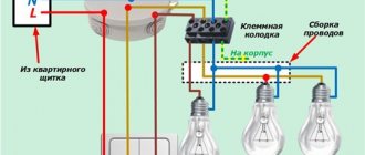
The distributed load is: lighting networks of houses (Figures 4, d and e), where risers 2 diverge from the input box 1 along the staircases, and from them, in turn, branches 3 are made into apartments. It is very important to understand that in lighting networks not all areas have a three-phase load.
Indeed, four supply wires go to the input box: A, B, C and 0. This is a real three-phase network - in it only the unbalance current of the entire house, determined by the unevenness of the load of the phases, passes through the neutral wire. The same applies to risers 2 in Figure 4, d, where the unbalance current passes through the neutral wire within a given staircase.
As for the risers in Figure 4, d, each of which has only one phase and zero, as well as branches to apartments, although they are powered by a three-phase network, they represent a single-phase load, since both the phase and neutral wires the same current passes (there are no other paths). Therefore, the cross-sections of the phase and neutral wires must be the same.
Figure 4. Star connection of electrical receivers.
Note: with a uniform load (Figure 4, a - c), a three-wire circuit is used. For uneven load (Figures 4, d and e) - four-wire.
To understand why they do this, let’s look at Figure 5. Figure 5a shows three groups of identical lamps (that is, having equal rated voltages, in our example 127 V, and equal powers). Under these conditions and a line voltage of 220 V, the lamps burn at normal incandescence. But the number of simultaneously switched on lamps, as well as their power in lighting networks, depends on the wishes of consumers. In a particular case, the load of one of the phases, for example phase c, can be completely turned off for some time (Figure 5, b). And then the loads of the other two phases will be connected in series. If they are equal, then the line voltage will be divided equally between them and the lamps will burn underpower, since 220 V / 2 = 110 V is less than the rated voltage of 127 V.
It is much worse if some of the lamps connected to one of the phases, for example to phase b, are disconnected, for example, as shown in Figure 5, c. Indeed, the resistance of one lamp is 3 times greater than the resistance of a group of three similar lamps connected in parallel. This means that the voltage of 220 V will be divided unevenly between them: the greater resistance will be 165 V (¾ of 220 V) and the lamp may burn out; the lower resistance will have 55 V (¼ of 220 V) 2.
With a four-wire circuit (Figure 5, d), the unevenness of the phase load does not have such a strong effect on the incandescence of the lamps due to the fact that the load of each phase is directly connected to both terminals of the phase winding of the generator or the secondary winding of the transformer.
It should, however, be noted that the unevenness of the phase load, even in the presence of a neutral wire, is an undesirable phenomenon, especially in cases where the load is powered from the secondary winding of the transformer connected in a star, since with an uneven load in the transformer its magnetic balance is disturbed. This important issue is discussed in the article “The Concept of Magnetic Balance of a Transformer.”
Figure 5. Features of connections in a lighting load star.
Unbalanced load when connecting receivers in a star
The load of a three-phase electrical network will be considered asymmetrical if at least one of the phase resistances is not equal to the others. Simply put, the phase resistances are not equal, for example: ra = rb = rc, xa = xb ≠ xc. In general, it is believed that an asymmetrical load occurs when one of the phases is disconnected.
Unsymmetry most often occurs when connecting single-phase electrical receivers to a three-phase network. They can have different powers, operating modes, different geographical locations, which also affects the magnitude of the phase load.
In the case when it is necessary to connect single-phase consumers of electrical energy, for a more uniform load they are divided into three groups of approximately equal power.
One terminal of single-phase consumers is connected to one of the three phases, and the second terminal is connected to the neutral wire. Since all electrical receivers are designed for the same voltage, within each phase they are connected in parallel.
The main feature of an electrical network with an asymmetric load is that it must necessarily have a neutral wire. This can be explained by the fact that in its absence, the magnitudes of phase voltages will largely depend on the magnitude of the unsymmetry of the network, that is, on the magnitude and nature of the resistance of each of the phases. Since phase resistances can vary quite widely depending on the number of connected electrical receivers, the voltages at electrical energy consumers will also vary widely, and this is unacceptable.
To illustrate the above, below is a vector diagram for a three-phase unbalanced circuit in the presence of a neutral wire:
Below is a vector diagram for the same circuit, but in the absence of a zero working (neutral) wire:
You can also watch a video that explains what can happen in an electrical circuit when the neutral wire breaks:
The need for a neutral wire will become even more obvious if you imagine that you need to connect a single-phase consumer to one of the phases, while the other two cannot be connected, since the receiver is designed for a phase voltage of 220 V, and not for a linear 380 V, as in this case you can get closed circuit for the flow of electric current? Only use a zero working conductor.
To increase the reliability of connecting electrical receivers, switching equipment (circuit breakers, fuses or disconnectors) is not installed in the neutral working conductor circuit.
Phase currents, shift angles, as well as phase powers with an asymmetric load will be different. To calculate their phase values, you can use formula (5), but formula (6) is no longer suitable for calculating three-phase power. To determine the power, you must use the expression:
If there is a need to determine the neutral wire current, then it is necessary to solve the problem using a complex method. If a vector diagram exists, then the current can be determined from it.
Example
In a lighting electrical network with a voltage of 220 V, there are 20 lamps in phase A, 10 lamps in phase B, and 5 lamps in phase C. Lamp parameters Unom = 127 V, Pnom = 100 W. It is necessary to determine the current of the neutral wire and each lamp.
Load distribution between phases
So, we always strive to load the phases evenly, that is, to attach the same power to each of them. When lighting with incandescent lamps, it is enough to correctly distribute the lamps between the phases. With fluorescent lighting, one more condition must be met, namely: connect the lamps located nearby to different phases. This is explained as follows: fluorescent lamps light up and go out 100 times per second, as alternating current with a frequency of 50 Hz passes through zero 100 times per second. Although we do not notice these pulsations of light, they have a harmful effect on vision. If lamps connected to different phases are located nearby, they will go out and light up at the same time, which will significantly reduce the depth of change in the luminous flux.
In addition, a profound change in the light flux can distort the actual picture of the movement of objects. Let, for example, a rotating object have time to make a full number of revolutions during the time the lamp goes out. This means that with each successive lighting the object will be visible in the same position, that is, it will seem motionless. If a rotating object manages to make a little less than a full revolution during the extinction, it will seem that the rotation is happening in the opposite direction. In industrial environments where there are mechanisms with rotating parts, this is extremely dangerous.
Why is it not allowed to include a fuse in the neutral wire?
Let's say a fuse is installed at the beginning of the riser, but it has blown (it is crossed out in Figure 5, d). In this case, the four-wire circuit turns into a three-wire circuit with all the disadvantages discussed above that are inherent in it with an uneven phase load.
According to the Rules for the Construction of Electrical Installations (PUE), at the beginning of the riser, it is not allowed to turn on a fuse (switch, circuit breaker) in the neutral wire. On the floor panels of staircases, from where power is distributed to apartments, fuses (circuit breakers) are installed only in the phase wire (Figure 5, e) or there are no fuses at all. In this case, however, switch B or circuit breaker A is required, with which the entire apartment can be disconnected from the riser.
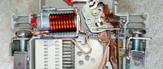
| Figure 6. Installation machine of type PAR-10 (automatic threaded fuse for a current of 10 A), screwed into the fuse instead of a plug. 1 – button to turn on; 2 – button to turn off. On the body of the machine, its rated data is written: the maximum network voltage, for example, 250 V (these machines are suitable for 127 and 220 V networks), and the rated current, for example, 10 A. The rated current can pass through the machine indefinitely. But if there is an overload (exceeding the rated current), the machine turns off, and the sooner the overload is greater. The machine switches off a short circuit instantly. |
But in apartments where people who do not have special electrical training have access to fuses P, which is why it is possible that the fuses are not in good enough condition, they must be installed on both wires in order to increase fire safety. Doesn't this contradict what was said above about the inadmissibility of including a fuse in the neutral wire? Not at all. Because the load within the apartment is single-phase, since the same current passes through both wires and fuses. This means that a blown fuse in any wire (phase or neutral, it doesn’t matter) cannot lead to overheating of the lamps: they will simply go out.
Fuses in lighting networks are giving way to automatic installation machines due to the fact that automatic machines provide more advanced protection and do not require replacement. New homes do not use fuses. In old apartments, instead of plugs in the fuses, you can install circuit breakers (Figure 6) with a threaded base without performing any installation work.
Neutral wire cross-section in four-wire networks
usually less than the cross-section of phase wires. Therefore, in cables for four-wire networks, three wires are thicker, and one, intended for the neutral wire, is thinner. Such a cable is designated, for example, as follows: 3×16+1×10 (three cores with a cross-section of 16 mm² and one with a cross-section of 10 mm²). However, in practice there is often a need to increase the cross-section of the neutral wire. Let's look at two examples.
Figure 7 shows three groups I, II, III of emergency lighting lamps, powered in normal mode from the secondary winding of transformer T (contactor K is on). When the AC voltage disappears, the contactor is switched off and the lamps are automatically switched to the battery. In this case, a “minus” is connected to wire 1 (which was previously neutral), and a “plus” is connected to the three wires 2, 3 and 4 (which were previously phase wires). While the lamps were powered by a transformer, there was a small current in wire 1, equal to the geometric sum of the currents in wires 2, 3 and 4. When the lamps switched to the battery, the current in wire 1 became equal to the arithmetic sum of the currents, that is, it exceeded the current in wire 2 , 3 or 4 is about 3 times. This means that the cross-section of wire 1 must be not less, but significantly larger than the cross-section of wire 2, 3 or 4.
Figure 7. The cross-section of the neutral wire in an emergency lighting circuit switched from alternating current to direct current must be larger than the cross-section of the phase wire.
The example shown in Figure 7 applies to a relatively small number of special electrical installations (for example, lighting for theaters and concert halls).
The following example is very widespread. We are talking about powering fluorescent lamps via a four-wire system. Under these conditions, even with a completely uniform phase load, higher harmonic currents, mainly the third harmonic current, pass through the neutral wire. This current is so significant that the cross-section of the fourth core of a conventional four-core cable is insufficient. Let's consider this issue in more detail.
Figure 8, a shows the sinusoidal current (curve 1) in phase A. This current would be when loaded with incandescent lamps. When loaded with fluorescent lamps, a third harmonic current additionally arises (curve 2). The addition of curves 1 and 2 gives curve 3, which shows that the current in phase A is non-sinusoidal. Figures 8, b and c show the curves for phases B and C. Comparing curves 2 in Figures 8, a, b and c, we see that the third harmonic currents are in phase . Therefore, in the neutral wire they are arithmetically summed up, forming curve 4 of triple frequency 150 Hz (Figure 8, d).
Figure 8. In the neutral wire of a four-wire three-phase network feeding fluorescent lamps, the third harmonic currents of all three phases are algebraically summed, so the cross-section of the neutral wire must be increased.
Depending on the switching circuit of fluorescent lamps, their type, the method of compensating the inductance of ballast chokes, and the like, the current in the neutral wire has a larger or smaller value, but in any case it is large and can even exceed the current in the phase wire.
Three-phase load connection options
3-phase transformers, electric motors and other electrical receivers are connected to the terminals of the generators according to a star (γ) or delta (Δ) circuit. The following features are taken into account:
— linear and phase voltage values of the generator differ by 1.732 times. Ul=√3Uф
;- the design of the electrical receiver is made to work with a certain voltage, called the rated voltage. It must be connected to the appropriate output circuits of the generator.
That is why it is necessary to choose the optimal ratio between the nominal voltages of the generator and the load when choosing a phase connection diagram.
If the rated load voltage is equal to the phase values of the generator, a star circuit is selected. With this method, the outputs from the receiver windings are connected to the common point “N”
, which is called neutral or zero.
Inputs from the windings (beginnings of phases) are switched to the linear terminals of the 3-phase generator A
,
B
and
C
connecting conductors.
Star connection options:
Currents flow in the connecting wires between the generator and the receiver. They are called linear currents.
Currents also flow in the receiver windings, which are called phase currents. Their direction from the beginning (input to the winding) to the end (output) is considered positive (+).
When the load phases are connected in series to the linear wires of the generator, the same electric currents IA, IB and IC
.
In the star circuit they are equal for the line and windings of the receiver, in other words: Il = If
.
In a star circuit with a neutral wire, a zero (does not mean that its value is zero) or neutral current flows in the neutral, denoted IN
.
The potential difference arising during the passage of current between the beginning and end of each winding in the receiver is called phase voltage, designated UAN, UBN and UCN
.
The potential differences between the connection points of the beginning of the phases are called linear voltages, denoted UAB
,
UBC
and
UCA
. Their values are the same for generator and load.
For electrical receivers of a star circuit with a neutral conductor, the corresponding phase voltage from the generator is connected to any winding. It is designated for the phase:
A: UАN=UАN= UА; B: UВN=UВN=UВ; C: UСN=UCN=UC.
Any phase works independently and does not depend on others. In it, currents (linear or phase) are determined by the formula according to Ohm’s law:
IA=UA/ZA; IВ=UВ/ZВ; IС=UC/ZС
.
Kirchhoff's first law allows you to determine the current in the neutral wire as the geometric sum of linear or phase currents by the expression: IN=IA+IB+IC
.
With equal and symmetrical loads (ZA=ZB=ZC)
the current value in the neutral wire is zero. IN=0. Therefore, symmetrical 3-phase electrical receivers (electric motors) are connected without a neutral wire.
In the case of violation of load symmetry, a current appears in the neutral conductor, the magnitude of which is determined by differences from the symmetrical components.
Such deviations are reduced at the design and production stage, which explains the insignificant current values in the neutral wire compared to phase/linear values.
Current ratios described by Kirchhoff’s 1st law for any loads of star circuits without a neutral wire (IA+IB+IC=0)
determine the interdependence of vectors.
A change in any one vector leads to the simultaneous transformation of the others, which manifests the dependence of the mode. The neutral current forms a potential difference with a value different from zero.
On the complex plane, the zero-sequence voltage is represented by the vector Un
, shifting the central point of connection of the phase voltage vectors for the receiver
(UАN, UВN, UСN)
, which lose equality with the phase voltages of the generator
(UA, UB, UC)
. A imbalance occurs with the phase voltages at the receiver.
Method for calculating current and voltage vectors for a star circuit without a neutral wire
.
The 2-node method calculates the neutral point displacement parameters for the neutral voltage vector (UN)
:
ZN
– value of the complex resistance of the neutral wire.
For a circuit without a neutral wire ZN=∞
.
Determination of phase voltages is based on calculating the potential difference between the beginnings and ends of the windings:
UАN=UA-UN; UВN=UВ-UN; UСN=UC-UN
.
Calculations of phase currents inside the receiver are made based on Ohm's law:
The magnitude of the current in the neutral conductor is calculated by the geometric sum of the input linear/phase currents based on Kirchhoff’s 1st law:
IN=IA+IB+IC.
Formulas for calculating the total power in phases:
With different loads in the phases, a voltage imbalance occurs in the circuit, which can lead to malfunctions. Therefore, it is prohibited to operate such loads in electrical receiver circuits without a neutral wire (often switched lighting, heating circuits, etc.).
Method for calculating current and voltage vectors for a triangle circuit
. When the values of the rated voltages of the power receiver are equal to the values of the linear voltages of the generator, a triangle circuit is used.
To create it in the receiver, the output of one winding is connected to the input of another with the output of the commutation point (which is the vertex of the triangle) to a terminal for connection by wires to the linear output of a 3-phase generator. This is how connections to phases A, B, C
.
IAB, IBC, ICA pass through the windings of such a receiver
.
And the currents supplied to the receiver from the generator through wires are called linear. They are designated IA, IB, IC
.
For the circuit under consideration, the supplied voltages from the line are equal to the phase voltages of the receiver UAB, UBC, UCA
. Each individual phase works independently without dependence on the others.
Calculation of phase currents is carried out according to Ohm's law:
Vectors of linear currents are described by Kirchhoff’s 1st law at the points of the triangle vertices and are calculated as the geometric difference of vectors in phases:
IA=IAB-ICA; IВ=IBC-IАВ; IC=ICA-IBC.
For a symmetrical load mode, the phase and linear currents are symmetrical, which are determined by the relation Il=√3Iph
. In an asymmetrical load mode, the relationships between linear and phase vectors are described by Kirchhoff’s 1st law.
An approximate vector relationship for an arbitrary 3-phase circuit operating according to a triangle circuit on a complex plane is presented in the vector diagram.
Star connection of transformer windings
Figure 9, a shows an example of connecting generator G, three transformers T1, T2, T3, electric motor D and single-phase loads N. In this example, the windings of the generator, transformers and electric motor are connected in a star. It is easy to see that the primary winding of transformer T1 is the electrical receiver for generator G, the secondary winding of transformer T1 serves as a current source for the primary winding of transformer T2. The secondary winding of transformer T2 is the current source for the primary winding of transformer T3. Its secondary winding is the current source for electric motor D and loads N.
Figure 9. Star connection of transformers.
A comparison of the circuits of transformers T1, T2 and T3 shows that they are not the same. Thus, the neutral point of the primary winding of transformer T1 is grounded and, therefore, connected to the grounded neutral point of generator G. The neutral points of the windings of transformer T2 are not brought out. The TZ transformer has a neutral point of the secondary winding, but it is isolated from the ground. Of course, the connections shown in Figure 9a are not at all necessary; they are given here only to illustrate typical cases of star connections.
Figures 9, b and c, respectively, show that both three single-phase transformers and one three-phase transformer can be connected into a star.
Figure 9, d shows examples of various star connections of transformer windings. Here the letters A, B, C are the beginnings, and X, Y, Z are the ends of the high voltage windings (HV); a, b, c and x, y, z – the beginnings and ends of the low voltage (LV) windings. Figure 9, d illustrates the star connections with the neutral removed of the HV winding (left), LV winding (in the center) and both windings (right).
For now, we will limit ourselves to a general remark that not all methods of connecting transformers into a star are equivalent. The difference in them is determined by a number of reasons that cannot be explained immediately, and therefore they will become clear in the course of further presentation.
Neutral grounding
Old releases of the PUE indicated that city electrical networks with voltages above 1000 V should be three-phase with an insulated neutral, and distribution networks in new cities should be three-phase, four-wire with a tightly grounded neutral at a voltage of 380/220 V. However, there are also networks with a voltage of 220/127 V , and their neutral is isolated. When the neutral is isolated, breakdown fuses .
The windings of power transformers of domestic factories with a voltage of 110 kV and higher are designed to work with a grounded neutral, since they have incomplete insulation on the side of the neutral terminals.
Neutral grounding and safety
Let us briefly explain why in networks up to 1000 V the neutral is grounded, for what reasons an isolated neutral is sometimes preferred, for which breakdown fuses are used.
Figure 10, a shows the secondary windings of transformer T, supplying a four-wire network with a voltage of 380/220 V, the neutral of which is isolated. Suppose that at the moment in question the insulation is completely intact. However, the figure shows three resistors r connected in a star. Its neutral is earth. These resistances conventionally represent the imperfection of wire insulation, which to some extent still conducts current. The same figure shows three capacitors C connected in a star. Its neutral is also the earth. Capacitors conventionally represent the electrical capacitance of wires relative to the ground, which is very important in AC electrical installations, since capacitance conducts current.
Figure 10. Neutral potential. Grounding in three-phase systems.
What voltages are there in the electrical installation in question? Between the linear wires 380 V, between each linear wire and the neutral of the transformer 220 V, between each linear wire and the ground 220 V. Why? Because the earth turned out to be the neutral of the stars of three equal resistances r and three equal capacitances C. And if the linear wire relative to the neutral of the transformer has the same voltage as relative to the ground, then it is clear that between the neutral of the transformer and the ground the voltage is zero 3.
It is unsafe for a person standing on the ground to touch one of the linear wires, since current passes through imperfect insulation, wire capacitance and the human body. At one point in time, its direction is shown in Figure 10, b. The current strength, and therefore the degree of danger, is determined by the values of resistances, capacitances and phase voltage. In other words, in this case the person is under a voltage of 220 V.
But what happens if one of the line wires becomes grounded and a person standing on the ground touches the other line wire? From Figure 10c, it is clear that the person will now be under a linear voltage of 380 V, rather than under a phase voltage, which is much more dangerous.
In networks with a grounded neutral, a person standing on the ground and touching the line wire comes under phase voltage (Figure 10, d). If at the same time another linear wire is grounded (Figure 10, d), then the fuse will blow, but there will be no increase in voltage from phase to linear (as in networks with an isolated neutral).
This means that both in a 380/220 V network with a grounded neutral, and in a 220/127 V network with an insulated neutral, a person touching a bare wire can come under 220 V voltage. But 380/220 V networks are more profitable than 220/127 networks V, since to transmit the same power at 380/220 V, wires of a smaller cross-section are needed.
Warning. To ensure safe grounding, a number of requirements must be strictly observed. This special issue is given special attention in the PUE; a number of books are devoted to this, including the books by M. R. Nayfeld “Grounding and other protective measures” and P. A. Dolin “The effect of electric current on the human body and first aid to the victim.”
Comparison of connection diagrams with each other
To compare both schemes with each other, it is necessary to calculate the electrical power developed by the electric motor when turned on in one way or another. To do this, we need to consider the concepts of linear (Iline) and phase (Iphase) currents. Phase current is the current flowing through the phase winding. Line current flows through a conductor connected to the winding terminal.
In networks up to 1000 volts, the source of electricity is a transformer, the secondary winding of which is connected in a star (otherwise it is impossible to organize a neutral wire) or a generator, the windings of which are connected according to the same circuit.
The figure shows that when connected by a star, the currents in the conductors and the currents in the windings of the electric motor are equal. The current in a phase is determined by the phase voltage:
where Z is the resistance of the winding of one phase, they can be taken equal. We can write down that
.
For a delta connection, the currents are different - they are determined by the linear voltages applied to the resistance Z:
.
Therefore, for this case .
Now you can compare the total power () consumed by electric motors with different circuits.
- for a star connection, the total power is equal to ;
- for a delta connection the total power is .
Thus, when switched on as a star, the electric motor develops power three times lower than when connected in a delta. This also leads to other positive consequences:
- starting currents are reduced;
- engine operation and starting become smoother;
- the electric motor copes well with short-term overloads;
- the thermal regime of the asynchronous motor becomes more gentle.
The other side of the coin is that a motor with star windings cannot develop maximum power. In some cases, the torque may not even be enough to spin the rotor.
Blowout fuse
Failure of insulation between the high and low voltage windings (HV and LV) of a transformer can lead to massive insulation breakdown in low voltage networks and injury to people. To prevent these dangerous phenomena in networks with an isolated neutral, breakdown fuses are used. The breakdown fuse is connected between the transformer neutral and the ground when connected in a star (Figures 11, a and c) or between one of the phase wires and the ground when connected in a triangle (see the article “Triangle connection diagram”), as shown in Figure 11, b .
Figure 11. Breakdown fuses in networks with isolated neutral.
In a breakdown fuse, one current-carrying part is connected to the neutral (phase) of the transformer, the other is grounded, but a mica gasket with holes is placed between them. At normal voltage, the gasket reliably isolates the neutral (phase) from the ground. However, when the higher voltage passes to the lower voltage winding, the blow-out fuse breaks through and grounds the windings.
When the neutral is solidly grounded, a breakdown fuse is not needed.
Phase and line voltages
To understand the differences between winding connection methods, you first need to understand the concepts of phase and line voltages. Phase voltage is the voltage between the beginning and end of one phase. Linear - between identical terminals of different phases.
For a three-phase network, linear voltages are the voltages between phases, for example, A and B, and phase voltages are between each phase and the neutral conductor.
So the voltages Ua, Ub, Uc will be phase, and Uab, Ubc, Uca will be linear. These voltages differ by several times. So, for a household and industrial network of 0.4 kV, linear voltages are 380 volts, and phase voltages are 220 volts.
Neutral grounding and uninterrupted power supply
In addition to safety conditions, there is another important issue, namely: uninterrupted power supply to consumers, when deciding on which it is not indifferent whether to ground the neutral or isolate it. The essence of the matter boils down to the following.
In a network with an isolated neutral, when the line wire is grounded, the fuses do not blow (the circuit breaker does not turn off), since there is no short circuit. Normal voltages are maintained between the linear wires, as well as between the linear wires and the neutral of the transformer, and electricity consumers can continue to work for some time.
In a network with a grounded neutral, a violation of the insulation of the line wire leads to a short circuit, fuses blow or the circuit breaker turns off, and the operation of consumers is disrupted. This means that the uninterrupted power supply is higher in networks with an isolated neutral.
It is necessary to especially emphasize the following most important circumstances:
a) Although consumers can operate in networks with an isolated neutral, this mode is dangerous for the isolation of other phases and the equipment connected to them. The fact is that when there is a metal short circuit to the ground of one of the phases, the voltage of the other phases relative to the ground increases by 1.73 times compared to the normal voltage, and the zero point voltage shifts and becomes equal to the phase voltage relative to the ground. Indeed, when the wire is grounded (Figure 12, a), the linear voltages AB, BC, CA remain the same; The phase voltages A0, B0, C0 do not change either. But in relation to the “ground” the voltages change. For phases A and C they increase to values AB and BC, respectively. For phase B, the voltage with respect to ground is reduced to zero. The neutral voltage relative to ground increases from zero to a value of 0V, equal to the phase voltage.
Figure 12. Neutral displacement in a network with an isolated neutral during emergency conditions. a – phase grounding; b – short circuit on the load of one of the phases; c – phase loss.
If a short circuit occurs through an arc, then overvoltages can be 2–2.5 times higher than the phase voltage. Capacitive currents of all phases will flow through the fault, which are large with long cable lines and can cause heating in places where the insulation is damaged. Therefore, power plants and substations often have devices that continuously monitor the state of insulation relative to ground. The principle of their operation is discussed in the articles “Open triangle. Open delta” and “Examples of instrument transformer connections”.
b) If the load neutral 0′ is not connected to the neutral 0 of the secondary winding of the transformer (Figure 12, b), then when one phase is short-circuited, the potential of line wire B falls into the load neutral 0′. This means that the load connected to phases A and C will be under significantly increased voltage (line voltage instead of phase voltage).
c) If the load neutral 0′ is not connected to the neutral 0 of the secondary winding of the transformer (Figure 12, c) and in one phase, for example in phase B, the fuse blows (crossed out), then at the loads of phases A and C the voltage will drop and become 220 V / 2 = 110 V instead of 220 / √3 = 127 V (220 / 127 V network is considered). The voltage at the terminals of a blown fuse will be 1.5 times greater than the phase fuse, that is, 127 × 1.5 = 190 V.
Asymmetrical mode of three-phase circuits
| • Three-phase circuits • |
- Three-phase systems
- Star connection of generator windings
- Connection of generator windings with a triangle
- Connecting energy receivers with a star
- Connecting energy receivers in a triangle
- Asymmetrical mode of three-phase circuits
- …
| • Site overview • |
- Electrical equipment up to 1000 V
- Electrical apparatus
- Electric cars
- Operation of electrical equipment
- Electrical equipment of electrical technological installations
- Electrical equipment for general industrial installations
- Electrical equipment for lifting and transport installations
- Electrical equipment of metalworking machines
- Electrical equipment above 1000 V
- High voltage electrical apparatus
- Electrical engineering
- Electric field
- DC electrical circuits
- Electromagnetism
- DC Electrical Machines
- Basic concepts related to alternating currents
- AC circuits
- Three-phase circuits
- Electrical measurements and instruments
- Transformers
- AC Electrical Machines
- Electrical installation
- Where does electrical installation of power supply of electrical equipment and wiring begin?
- Electrical wiring installation
- Calculation of power consumption, cable cross-section and circuit breaker rating
- Electrical installation work and cable laying in residential and non-residential premises
- Electrical installation work on disconnecting junction boxes and electrical equipment
- Electrical installation and grounding of sockets
- Electrical installation of potential equalization
- Electrical installation of the ground loop
- Electrical installation of a modular pin ground loop
- Electrical installation of heating cable for underfloor heating
- Electrical installation work on laying cables in the ground
- Electricity in a private house
- Power supply project
| • Electrical engineering • |
- Electric field
- DC electrical circuits
- Electromagnetism
- DC Electrical Machines
- Basic concepts related to alternating currents
- AC circuits
- Three-phase circuits
- Electrical measurements and instruments
- Transformers
- AC Electrical Machines
- …
ELECTROSPETS
ELECTROSPETS
a) Purpose of the neutral wire . With an asymmetrical load by a star without a neutral wire (in Fig. 11.19 the key is open), the resistances of all phases are not the same: ZA ZB ZC. As a result, a neutral bias voltage UN'N appears, determined by the formula of two nodes:
This voltage UN, acting between points N and N' (Fig. 11.19) , is shown in Fig. 11.20 . For any direction of the UN vector, the voltages on the load phases will be unequal.
When the receivers are turned on and off, the conductivities of the YA, YB and YC phases change in an arbitrary manner, this leads to a change in the neutral bias voltage UN, leading, in turn, to an arbitrary change in the voltages on the load phases. The vast majority of electrical power receivers operate only at the rated supply voltage. Therefore, a star connection without a neutral wire for an asymmetrical or variable load is practically not used due to the inability to provide the rated supply voltage. With a large number of receivers, statistically on “average” providing approximately the same phase load, despite the switching on and off of individual consumers, the neutral shift is small. This allows the use of a star connection without a neutral wire for powerful power lines to transformer substations with voltages up to 6.3 kV. A star connection without a neutral wire is also used in devices intended for monitoring and analyzing the modes of three-phase circuits.
b) Star connection with neutral wire . To connect a star with a neutral wire (in Fig. 11.19 the key is closed), we also determine the neutral voltage using the two-node formula:
In real power supply systems, the conductivity of the neutral wire YN is much greater than the conductivity of the phases and in practice we can assume that the resistance of the neutral wire is close to zero. Then, as YN→ ∞, the denominator in the above formula tends to infinity, UN→ 0, and in the presence of a neutral wire with a sufficiently low resistance, there is no shift in the zero point potential N' of the load. On the load phases, regardless of their resistance, the voltages that make up a symmetrical three-phase system are maintained. Load phase currents are determined by Ohm's law:
In Fig. Figure 11.22 shows a vector diagram of currents with an asymmetrical active load. From the vector diagram it is clear that the phase currents with an asymmetric load are not equal in magnitude, but in the general case are shifted in phase by angles not equal to 120°, i.e. they do not represent a symmetrical three-phase system. The neutral wire current (see Fig. 11.14) can be determined by Kirchhoff's first law for node N' - Fig. 11.22 (the figure shows an auxiliary current vector equal to the sum of currents IA + IC):
The greater the load phase asymmetry, the greater the “equalizing” current IN of the neutral wire.
A star connection with a neutral wire is widely used for power supply of residential and public buildings, industrial energy receivers and in other cases with numerous receivers that are turned on and off independently of each other.
c) Triangle connection . If we neglect the resistance of the connecting wires, then the voltages on the load phases are equal to the linear voltages of the three-phase source. Phase currents with an asymmetrical load ZАB ZВС ZСA are determined according to Ohm’s law:
In Fig. Figure 11.25 shows a vector diagram of currents with an asymmetrical active load. Linear currents are determined according to Kirchhoff's first law for nodes A, B and C in Fig. 11.17 :
As can be seen from the vector diagram (Fig. 11.25) , the linear currents are not equal in magnitude and are shifted in phase by angles not equal to 120°. In the general case, the phase currents are not equal in magnitude and are shifted in phase by angles not equal to 120°.
The vector diagram of linear currents is shown in Fig. 11.25 .
d) Emergency modes in three-phase circuits . Special cases of asymmetrical modes are emergency modes in three-phase circuits: breaks in the neutral and linear wires, short circuits in phases . Absolutely safe are breaks in the phases of the load connected by a triangle or star to the neutral wire (phase disconnections). Short circuits in the load phases of such connections are emergency and fire hazardous. All other cases lead to a sharp change in the rated voltages in the load phases and can lead to an emergency. A break in the neutral wire of an asymmetric star was considered in Example 11.9.