Types and properties of semiconductors
In order for an electric current to appear, there must be mobile particles that carry charges. The electrical conductivity of a substance depends on the number of such carriers per unit volume. In dielectrics they are practically absent, and in semiconductors free carriers are present only in small quantities. Consequently, the resistivity of semiconductors is very high, and in dielectrics it is even higher. There are different types of these materials, each with their own specific properties.
All semiconductors can be divided into several main types. Among them, the leaders are pure or proprietary materials, which do not contain any impurities.
They are characterized by a crystalline structure, where the atoms are arranged in a periodic order at its nodes. Here there is a stable mutual connection between each atom and four atoms located nearby. This makes it possible to form permanent electron shells, which contain eight electrons. At a temperature equal to absolute zero, such a semiconductor becomes an insulator, since all electrons are connected by covalent bonds.
When the temperature increases or any irradiation occurs, electrons can escape from covalent bonds and become free charge carriers. When moving, the free spaces are gradually occupied by other electrons, so the electric current flows only in one direction.
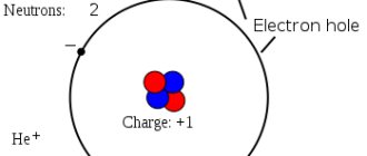
In electronic semiconductors, in addition to the four atoms that form the basis of the crystal lattice, there are so-called donors. They are impurities in the form of pentavalent atoms. The electron contained in such an atom cannot normally enter into a covalent bond and is therefore separated from the donor. Thus, it turns into a free charge carrier. In turn, the donor becomes a positive ion, this can happen even at room temperature.
Methods for measuring resistivity of semiconductor materials
Bibliographic description:
Radkov, A.V. Methods for measuring the resistivity of semiconductor materials / A.V. Radkov, A.A. Malakhanov. — Text: direct // Current issues of technical sciences: materials of the V International. scientific conf. (St. Petersburg, February 2019). - St. Petersburg: Own publishing house, 2022. - pp. 18-24. — URL: https://moluch.ru/conf/tech/archive/324/14799/ (access date: 02/09/2022).
This article discusses contact and non-contact methods for measuring the resistivity of semiconductor materials.
Key words: resistivity, contact method, non-contact method, two-probe method, single-probe method, four-probe method, Van der Pauw method.
When studying the electrical properties of semiconductors and producing semiconductor materials, structures and devices, it becomes necessary to measure the electrical resistivity of semiconductor materials. Resistivity measurement is carried out not only to establish its value, but also to determine other important parameters of the semiconductor material based on theoretical calculations or additional experimental data. Ideally, measuring the resistivity of semiconductor materials should not lead to destruction of the sample and should not require special processing.
There are two groups of methods for measuring the resistivity of semiconductor materials - contact and non-contact. Many methods are based on measuring the potential difference across a certain area of the sample through which an electric current is passed. With the contact method, direct contact occurs with the semiconductor sample, as a result of which the sample is destroyed. Therefore, there is a need for non-contact methods that do not require direct contact with the sample.
To measure the resistivity of samples with a regular geometric shape and a constant cross-section, a two-probe method and a single-probe method with signal differentiation are used. When using the two-probe method, ohmic contacts (K1 and K2) are made on the end faces of the sample, for example in the form of a rectangular plate. An electric current is passed through these contacts along the sample. On one of the sample surfaces along the current line, two contacts are installed in the form of metal needles - probes (Z1 and Z2), which have a small contact area and allow you to change the potential difference. Between them there is a zero device G and a potentiometer P (Fig. 1.).
Rice. 1. Scheme for measuring resistivity using the two-probe method
Rice. 2. Measurement circuit with a high-resistance voltmeter connected between the probes
The current through the sample is supplied from a controlled DC source (IT), which guarantees sufficient stability of the current over time. The current strength is measured with a milliammeter, and the potential difference is measured with a semi-automatic compensating potentiometer or an electronic digital voltmeter with high input resistance (Fig. 2).
where is the potential difference between the measuring or potential probes, V; — current flowing through the sample, A; — distance between probes, cm; — cross-sectional area, ; — resistance of the sample section between the probes; - resistivity, .
The error in measuring voltage and current when using instruments with digital display does not exceed 0.1%. However, the systematic measurement error between potential probes depends on the contact resistance of the probe with the sample, which can be several times greater than the resistance of the sample. To eliminate the influence of contact resistance on the measurement result, it is necessary to extremely reduce the current flowing through them. For this, voltmeters with high input resistance (Ohm or more) are used, and the insulation resistance of each probe relative to any element of the measuring setup must be greater than this value.
The deviation of the actual probe contact from the theoretical model of a point potential contact also introduces a systematic error in the measurement result.
A modified two-probe method is a single-probe method with signal differentiation (Fig. 3).
Rice. 3 Single-probe method with signal differentiation
In this case, the voltage drop is measured between two probes, one of which is stationary, and the second is moving at a speed. The signal enters the differentiating chain. In this case, the resistivity can be calculated using the formula:
where is the voltage drop across the resistance.
Thus, the above formula is equivalent to the formula for the two-probe method using a head in which the distance between the probes is . The most promising single-probe method is when using a moving probe and introducing a differentiating element into the measurement circuit. The resolution of the method under consideration is uniquely determined by the value of the effective interprobe distance. Therefore, when using a single-probe method to identify microinhomogeneities, it is necessary to select the optimal parameter values.
A feature of the single-probe, as well as the double-probe, method is the ability to measure a certain average resistivity value over the entire cross-section between the points where the probes are located, that is, with a constant cross-section.
However, in production there are tasks that cannot be accomplished using the methods discussed. Examples of such tasks can be both measuring the resistance of materials in various areas of a semiconductor ingot without violating its integrity, and determining the resistivity of a material in a wafer of irregular geometric shape. Such problems led to the creation of special methods for determining resistivity without imposing strict requirements on the geometry of the samples under study. One such method is the four-probe method.
Rice. 4. Scheme for measuring resistivity using the four-probe method
Let four point probes be installed on the sample surface, as shown in Fig. 4. Distance between adjacent probes, a current passes through the two outermost probes 1 and 4, which creates a potential difference between probes 2 and 3. The potential difference is a function of the current strength, resistivity, distance and geometric dimensions of the samples.
The potential difference between probes 2 and 3 is found by the formula:
From expression (3) we find the resistivity. The measurement of the potential difference in the four-probe method is carried out as in the two-probe method. The effect on the measurement results of non-ohmic contacts of potential probes 2 and 3 is the same.
The four-probe measurement method is widely used in the manufacturing process of semiconductor materials and in the creation of semiconductor devices. Expressions connecting and were obtained for different cases. When the distance from the probes to the sample surfaces is significantly greater than , the sample can be considered as a half-space. And the resistivity can be determined by expression (3). The smaller , the smaller the samples, formula (3) is valid. In Fig. Figure 5 shows for two values the dimensions of the samples (in centimeters), at which calculation using formula (3), which does not take into account their limbs, leads to an error of 1%.
Rice. 5. Samples of different geometries
The two-combination four-probe method is a variation of the four-probe method with a linear arrangement of the probe system, but unlike it, the measurement is carried out twice with different combinations of current and potential probes.
Due to its high accuracy and simplified measurement procedure, the two-combination four-probe method is used to study the distribution of the resistance surface of ion-doped layers over the wafer area. Based on this method, automated measuring devices with stepwise movement of the probe head along the surface of the sample have been created.
Van der Pauw developed a modified four-probe method that is applicable to measuring the resistivity of flat samples (plates) of any shape. With this method, the contacts are located along the edges of the plate (Fig. 6). Passing current through probes 1 and 2, measure the voltage and calculate the resistance between probes 3 and 4: Then, passing current through probes 1 and 4, determine the resistance between probes 2 and 3: .
Specific resistance is calculated using the formula
where is the theoretically calculated correction function. The value of this function depending on is shown in Fig. 7.
Rice. 6. Modified van der Pauw four-probe method: a) measurement of flat plates of arbitrary shape, b) placement of contact probes when sorting crystals
Rice. 7. Correction function in the Van der Pauw method
It can be seen that at . As can be seen from relation (4), the calculation formula does not include the distances between the probes. The formulas contain quantities that can be measured with high accuracy.
For plates of the correct geometric dimensions, the resistivity can be determined with an error of less than 2%.
This method can be used to quickly sort small-sized plates based on resistivity and concentration (Fig. 6).
In the four-probe method and the Van der Pauw method, the same requirements are imposed on the conductive contacts as in the two-probe method: the flow of current through them should not lead to a change in the concentration of charge carriers in the semiconductor. This requirement must be especially taken into account if the distance between the probes is comparable to or less than the length of the diffusion displacement of charge carriers.
The methods discussed above lead to the destruction of samples, so we will consider non-contact methods that do not require direct contact with the sample. The general idea of non-contact methods for determining resistivity is as follows. A current is excited in the sample without the use of contacts, the strength of which depends on the resistivity of the sample, which is determined by measuring any quantity functionally related to the current. To excite the current, samples are placed in an alternating magnetic, electric or, in general, electromagnetic field. The magnitude of the flowing current and the resistivity of the sample are judged by measuring the strength of interaction of the current with the magnetic field, or by measuring values determined by the change in the energy of the field in which the sample is located.
As an example, let us consider a method for determining resistivity from the force of interaction induced in a sample with a magnetic field. Let a scar-shaped semiconductor sample be placed in a rotating magnetic field (Fig. 8). The magnetic field induction vector rotates in the plane with angular frequency , and its absolute value remains unchanged. The field induces a current in the sample. The interaction of this field with the current leads to the emergence of a moment of force, which drags the sample along with the field, that is, a situation arises, as in an asynchronous motor. Based on the magnitude of the moment of force, the resistivity of the sample can be determined.
Rice. 8. Spherical sample in a rotating magnetic field
To determine resistivity, you can either place the sample in a rotating magnetic field or rotate the sample in a constant magnetic field. In the installation (Fig. 9), using the first possibility, sample 1 is suspended on a thin elastic thread 2, to which a mirror 3 is attached, reflecting a beam of light 4. When the magnetic field is turned on, the sample, the mirror and the beam reflecting from it rotate. The angle of rotation of the beam, where the value of the constant is determined by the properties of the threads, using a sample with a known resistivity, for which the moment of force can be calculated using the formula:
or
where in (5) is the radius of the sample; formula (6) is used for the case when the sample has the shape of a cylinder with a base radius and height . Having measured , determine and then calculate the resistivity.
Rice. 9. To determine the torque in a rotating magnetic field
The lower the resistivity, the greater the torque and the easier it is to carry out measurements. The method is limited by large ones. Making a spherical or cylinder shaped sample can be challenging. Such methods are most effective for low values of sample resistivity, when the forces acting on them are large.
Literature:
- Pavlov, I. P. Methods for measuring parameters of semiconductor materials: textbook. for universities for special purposes “Semiconductor and microelectronic devices.”/I. P. Pavlov. — 2nd ed., revised. and additional - M.: Higher. school, 1987. - 239 p., ill.
- Kovtonyuk, N.F., Measurement of parameters of semiconductor materials/N. F. Kovtonyuk, Yu. A. Kontsevoy. - M.: Publishing house "Metallurgy", 1970. - 432 pp., ill.
- Vorobyov, Yu. V. Methods for studying semiconductors/Yu. V. Vorobyov, V.N., Dobrovolsky, V.I. Strikha. — Kyiv: Vysha school. Head Publishing House, 1988. - 232 p., ill.
- Batavin, V.V. Measurement of parameters of semiconductor materials and structures/V. V. Batavin, Yu. A. Kontsevoy, Yu. F. Fedorovich. - M.: Radio and Communications, 1985. - 264 p., ill.
Key terms
(automatically generated)
: resistivity, probe, four-probe method, single-probe method, potential difference, sample surface, measurement circuit, current, direct contact, cross section.
Factors affecting the resistance of semiconductors
It has been experimentally established that as the temperature increases, the electrical resistance in semiconductor crystals decreases. This is due to the fact that when the crystal is heated, the number of free electrons increases, and their concentration increases accordingly. The changing resistance of semiconductors under the influence of temperature is used to create special devices called thermistors.
In order to make a thermistor, semiconductors are used, which are oxides of individual metals in a mixed state. The finished substance is placed in a protective metal case with insulated terminals. With their help, the device is connected to the electrical circuit.
Thermistors are used to measure temperature or to maintain it in a given mode in any devices. The main principle of their operation is changing resistance with temperature changes. The same principle is used in photoresistors. Here the resistance value changes depending on the lighting level.

