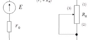
During the operation of energy systems, issues related to the need for any established electrical quantities in similar quantities with changed values in a certain proportion are often resolved. To do this, you need to know how a current transformer works, the operation of which is based on the law of electromagnetic induction, applied to electric and magnetic fields. During operation, the primary value of the current vector flowing in the power circuit is converted into a secondary current with a reduced value. During such a transformation, modulus proportionality and accurate angle transfer are maintained.
Transformer
A transformer is a static electromagnetic device having two or more inductively coupled windings on any magnetic circuit and designed to convert, through electromagnetic induction, one or more systems (voltages) of alternating current into one or more other systems (voltages), without changing the frequency.
The transformer performs alternating voltage conversion and/or galvanic isolation in a wide variety of applications - electrical power, electronics and radio engineering.
Structurally, a transformer can consist of one (autotransformer) or several insulated wire or tape windings (coils), covered by a common magnetic flux, wound, as a rule, on a magnetic core (core) of ferromagnetic soft magnetic material.
What are the main technical characteristics of transformers: let’s summarize the information
- transformers differ in voltage level. And the types differ in high-, low-voltage and high-potential voltage. All information is indicated in the accompanying documents.
- Transformers have differences in the way they convert energy. And the units are increasing and decreasing.
- Transformers are also characterized by the number of phases. And there is single-phase or three-phase equipment.
- transformers are equipped with a different number of windings and the shape of magnetic cores, which can be rod, armored or toroidal.
Thus, the characteristics of transformers are considered standard and understandable to specialists. Transformers are always used for their intended purpose and serve their intended life if the conditions of their operation are met. There are failures in the program of units, but if there are voltage drops in the network or operating rules are violated. Problems can be avoided if you establish uninterrupted operation and activate the protection system of the unit itself; it is better for it to automatically turn off than to manifest itself as a short circuit.
Basic principles of transformer operation
The operation of a transformer is based on two basic principles:
- A time-varying electric current creates a time-varying magnetic field (electromagnetism)
- A change in the magnetic flux passing through a winding creates an emf in that winding (electromagnetic induction)
One of the windings, called the primary winding, is supplied with voltage from an external source. The alternating magnetizing current flowing through the primary winding creates an alternating magnetic flux in the magnetic core. As a result of electromagnetic induction, an alternating magnetic flux in the magnetic circuit creates in all windings, including the primary, an induced emf proportional to the first derivative of the magnetic flux, with a sinusoidal current shifted 90° in the opposite direction with respect to the magnetic flux.
Some transformers operating at high or ultra-high frequencies may not have a magnetic core.
The voltage shape in the secondary winding is related to the voltage shape in the primary winding in a rather complex way. Thanks to this complexity, it was possible to create a number of special transformers that can serve as current amplifiers, frequency multipliers, signal generators, etc.
The exception is the power transformer. In the case of the classic AC transformer proposed by P. Yablochkov, it converts the sinusoidal input voltage into the same sinusoidal voltage at the output of the secondary winding.
In the case of a power transformer operating in the Motovilov Converter circuit, it converts the direct power current of the primary winding into the direct power current of the secondary winding with a rectangular alternating voltage on both windings. The latter is rectified into a constant voltage so that constant currents at a constant voltage act at the input and output of the Motovilov circuit.
General structure and principle of operation
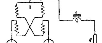
Let's consider the design of a simple transformer with two coils mounted on a closed magnetic circuit (see Fig. 2). The coil that receives current will be called the primary coil, and the output coil will be called the secondary coil.
Figure 2. Transformer design
Virtually all types of transformers use electromagnetic induction to convert the voltage entering the primary winding circuit. In this case, the output voltage is removed from the secondary windings. They differ only in shape, magnetic core materials and methods of winding the coils.
Ferromagnetic cores are used in low-frequency models. The following materials are used for such cores:
- steel;
- permalloy;
- ferrite.
In some high-frequency models, magnetic cores may be absent, and in some products materials made from high-frequency ferrite or alsifer are used.
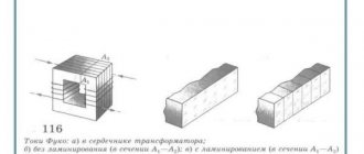
Due to the fact that the characteristics of ferromagnets are characterized by nonlinear magnetization, the cores are assembled from sheet materials onto which windings are placed. Nonlinear inductance leads to hysteresis, to reduce which the method of lamination of magnetic circuits is used.
The core shape can be W-shaped or toroidal.
Basic principles of operation
When a sinusoidal current is supplied to the terminals of the primary windings, it creates an alternating magnetic field in the second coil that penetrates the magnetic circuit. In turn, a change in the magnetic flux provokes the induction of an emf in the coils. In this case, the magnitude of the EMF voltage in the windings is proportional to the number of turns and the frequency of the current. The ratio of the number of turns in the primary winding circuit to the number of turns of the secondary coil is called the transformation ratio: k = W1 / W2, where the symbols W1 and W2 indicate the number of turns in the coils.
If k > 1, then the transformer is step-up, and if 0 < k < 1, then the transformer is step-down. For example, when the number of turns that make up the primary winding is three times less than the number of secondary turns, then k = 1/3, then U2 = 1/3 U1.
Main parts of the transformer design
The main parts of the transformer design are:
- magnetic circuit
- windings
- frame for windings
- insulation
- cooling system
- other elements (for installation, access to winding terminals, transformer protection, etc.)
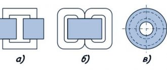
In practical transformer design, the manufacturer chooses between three different basic concepts:
- Rod
- Armored
- Toroidal
Neither of these concepts affects the performance or operational reliability of the transformer, but there are significant differences in their manufacturing process. Each manufacturer chooses the concept that it considers most convenient from a manufacturing point of view, and strives to apply this concept throughout the entire production volume.
While bar-type windings enclose a core, armor-type core encloses the windings. If you look at the active component (i.e. the core with windings) of the rod type, the windings are clearly visible, but they hide the rods of the core magnetic system behind them. Only the upper and lower yoke of the core are visible. In an armor-type design, the core hides the main part of the windings.
Another difference is that the axis of the rod-type windings, as a rule, has a vertical position, while in an armored structure it can be horizontal or vertical.
What is overvoltage mode, maybe it is as dangerous as a short circuit?
Subject to the technical characteristics of TM transformers, each standard equipment has windings covered with a special layer of insulation so that the unit can withstand a certain voltage level. But power surges are possible in the network, which is not very good, since preconditions for overvoltage appear and the negative impact of atmospheric phenomena on the power system appears.
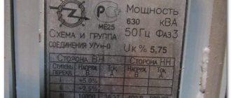
For reference, let us clarify that in the transformer’s passport, the developers indicate the permissible voltage value at which the characteristics of the TM transformer adequately and properly manifest themselves in operation. At normal voltage, the winding insulation system copes with the loads, even if short-term overvoltages appear in the network, this turns out to be not so critical.
Just like against a short circuit, protection means are thought out in the magnetic sphere of the transformer, which, when harbingers of an emergency situation appear, are triggered, turning off the power or reducing the number of discharge pulses supplied.
Transformer operating modes
Idle mode
This mode is characterized by an open secondary circuit of the transformer, as a result of which no current flows in it. No-load current flows through the primary winding, the main component of which is the reactive magnetizing current. Using the no-load test, you can determine the efficiency of the transformer, the transformation ratio, as well as losses in the core (the so-called “steel losses”).
Load mode
This mode is characterized by the operation of a transformer with a connected source in the primary circuit and a load in the secondary circuit of the transformer. The load current flows in the secondary winding, and the current flows in the primary winding, which can be represented as the sum of the load current (calculated from the ratio of the number of turns of the windings and the secondary current) and the no-load current. This mode is the main operating mode for the transformer.
Short circuit mode
This mode is obtained as a result of short-circuiting the secondary circuit. This is a type of load mode in which the resistance of the secondary winding is the only load. Using the short circuit experiment, it is possible to determine the heating losses of the windings in the transformer circuit (“copper losses”). This phenomenon is taken into account in the equivalent circuit of a real transformer using active resistance.
Idle mode
When the secondary current is equal to zero (no-load mode), the induced emf in the primary winding almost completely compensates for the voltage of the power source, therefore the current flowing through the primary winding is equal to the alternating magnetizing current, there are no load currents. For a transformer with a core made of soft magnetic material (ferromagnetic material, transformer steel), the no-load current characterizes the amount of losses in the core (for eddy currents and hysteresis) and the reactive power of the magnetization reversal of the magnetic core. The power loss can be calculated by multiplying the active component of the no-load current by the voltage supplied to the transformer.
For a transformer without a ferromagnetic core, there are no losses due to magnetization reversal, and the no-load current is determined by the inductance resistance of the primary winding, which is proportional to the frequency of the alternating current and the magnitude of the inductance.
The voltage on the secondary winding is determined to a first approximation by Faraday's law.
Short circuit mode
In short circuit mode, a small alternating voltage is applied to the primary winding of the transformer, and the terminals of the secondary winding are short-circuited. The voltage at the input is set such that the short circuit current is equal to the rated (calculated) current of the transformer. Under such conditions, the magnitude of the short circuit voltage characterizes the losses in the transformer windings, the losses in the ohmic resistance. The power loss can be calculated by multiplying the short circuit voltage by the short circuit current.
This mode is widely used in measuring current transformers.
Load mode
When a load is connected to the secondary winding, a load current appears in the secondary circuit, creating a magnetic flux in the magnetic circuit directed opposite to the magnetic flux created by the primary winding. As a result, the equality of the induced emf and the power source emf is violated in the primary circuit, which leads to an increase in the current in the primary winding until the magnetic flux reaches almost the same value.
The instantaneous magnetic flux in the magnetic circuit of the transformer is determined by the time integral of the instantaneous value of the emf in the primary winding and, in the case of a sinusoidal voltage, is shifted in phase by 90° with respect to the emf. The EMF induced in the secondary windings is proportional to the first derivative of the magnetic flux and for any current shape coincides in phase and shape with the EMF in the primary winding.
What happens when there is a short circuit in a transformer: what is important to remember
Even schoolchildren know that a short circuit does not bode well. But why does this happen? A short circuit occurs when the load supplied to the transformer becomes short-circuited, but at the same time it continues to be affected by the entire power supply of the voltage source. Undoubtedly, a short circuit is the most dangerous mode of operation of a transformer, which cannot be predicted, and therefore cannot be prevented or controlled. All that remains is to be vigilant and try to anticipate dangerous power surges in the network, or use protective elements for the main line, which monitor possible current surges, and when the load increases, they automatically turn off the equipment almost instantly. And this is good, since during a short circuit there is such a huge thermal release that it can even burn wires or completely render all equipment unusable. It can't be done without a major overhaul.
Types of transformers
Power transformer
AC power transformer is a transformer designed to convert electrical energy in electrical networks and in installations intended for receiving and using electrical energy. The word “power” reflects the operation of this type of transformer with high power. The need to use power transformers is due to the different operating voltages of power lines (35-750 kV), city electrical networks (usually 6.10 kV), the voltage supplied to end consumers (0.4 kV, also known as 380/220 V) and the voltage required for the operation of electrical machines and electrical appliances (various from units of volts to hundreds of kilovolts).
A DC power transformer is used to directly convert voltage in DC circuits. The term “power” shows the difference between such transformers and measuring devices of the “DC Transformer” class.
Autotransformer
An autotransformer is a variant of a transformer in which the primary and secondary windings are directly connected, and due to this they have not only an electromagnetic connection, but also an electrical one. The autotransformer winding has several terminals (at least 3), by connecting to which you can obtain different voltages. The advantage of an autotransformer is higher efficiency, since only part of the power is converted - this is especially significant when the input and output voltages differ only slightly.
The disadvantage is the lack of electrical insulation (galvanic isolation) between the primary and secondary circuits. The use of autotransformers is economically justified instead of conventional transformers for connecting effectively grounded networks with voltages of 110 kV and higher with transformation ratios of no more than 3-4. A significant advantage is lower consumption of steel for the core, copper for windings, lower weight and dimensions, and ultimately lower cost.
Current transformer
Current transformer is a transformer powered by a current source. A typical application is to reduce the primary current to a value used in measurement, protection, control and signaling circuits, in addition, the current transformer provides galvanic isolation (different from shunt current measurement circuits). The rated current of the secondary winding is 1A, 5A. The primary winding of the current transformer is connected to the circuit with the measured alternating current, and the measuring instruments are connected to the secondary winding. The current flowing through the secondary winding of a current transformer is equal to the primary winding current divided by the transformation ratio. ATTENTION! The secondary winding of the current transformer must be reliably short-circuited or short-circuited to the low-impedance load of the measuring instrument. If the circuit is accidentally or intentionally broken, a voltage surge occurs, which is dangerous for the insulation, surrounding electrical appliances and the life of technical personnel! Therefore, according to the rules of technical operation, it is necessary to short-circuit unused secondary windings, and all secondary windings of current transformers must be grounded.
Voltage transformer
Voltage transformer - a transformer powered by a voltage source. Typical applications are the conversion of high voltage to low voltage in circuits, measuring circuits and relay protection and automation circuits. The use of a voltage transformer allows you to isolate the logical protection circuits and measurement circuits from the high voltage circuit.
Pulse transformer
A pulse transformer is a transformer designed to convert pulse signals with a pulse duration of up to tens of microseconds with minimal distortion of the pulse shape. The main application is the transmission of a rectangular electrical pulse (maximum steep front and cutoff, relatively constant amplitude). It serves to transform short-term video voltage pulses, usually periodically repeated with a high duty cycle. In most cases, the main requirement for IT is the undistorted transmission of the shape of the transformed voltage pulses; When an IT input is exposed to a voltage of one form or another, it is desirable to obtain a voltage pulse of the same shape at the output, but perhaps of a different amplitude or polarity.
Isolation transformer
An isolation transformer is a transformer whose primary winding is not electrically connected to the secondary windings. Power isolation transformers are designed to improve the safety of electrical networks in case of accidental simultaneous contact with the ground and live parts or non-current parts that may be energized in the event of insulation damage. Signal isolation transformers provide galvanic isolation of electrical circuits.
Matching transformer
Matching transformer is a transformer used to match the resistance of various parts (cascades) of electronic circuits with minimal distortion of the signal shape. At the same time, the matching transformer ensures the creation of galvanic isolation between sections of the circuits.
Peak transformer
Peak transformer is a transformer that converts a sinusoidal voltage into a pulse voltage with a polarity changing every half cycle.
Twin throttle
A dual choke (counter inductive filter) is a transformer with two identical windings. Thanks to the mutual induction of the coils, it is more efficient than a conventional inductor with the same dimensions. Twin chokes are widely used as input filters for power supplies; in differential signal filters of digital lines, as well as in audio technology.
Transfluxor
A transfluxor is a type of transformer used to store information. The main difference from a conventional transformer is the large amount of residual magnetization of the magnetic circuit. In other words, transfluxors can act as memory elements. In addition, transfluxors were often equipped with additional windings that provided initial magnetization and set their operating modes. This feature made it possible (in combination with other elements) to build circuits of controlled generators, comparison elements and artificial neurons on transfluxors.
Voltage transformers can be classified according to the following criteria:
- by the presence or absence of grounding of terminal X of the primary winding;
- by number of phases;
- by the number of windings;
- by the presence of a compensation winding or winding for monitoring network insulation;
- by type of insulation;
- by accuracy class;
- by cooling method;
- at the installation site;
- by rated voltage factor;
- by voltage class according to GOST 1516.3, kV;
- according to the highest operating voltage, kV;
- according to the rated voltage of the primary winding;
- according to the rated voltage of the secondary winding. If there are two secondary windings, then according to the rated voltage of the main secondary winding;
- according to the rated voltage of the additional secondary winding (if any);
- by rated power of the transformer, kVA (kilovolt-amperes);
- by maximum power of the transformer, kVA (kilovolt-amperes);
- by short circuit voltage;
- by the highest winding current;
- by working position in space;
- according to the degree of protection of the IP housing;
- according to climatic design;
- according to accommodation category according to GOST 15150;
- by operating temperature range;
- by overall dimensions;
- by weight, volume;
- depending on the model, brand, manufacturer.
Based on the number of phases, voltage transformers can be divided into the following groups:
- single-phase;
- three-phase.
Both single-phase and three-phase voltage transformers are widely used in three-phase power supply. Three-phase voltage transformers are installed in a three-phase electrical network. Single-phase voltage transformers are also recommended to be installed in a three-phase electrical network in a group of one transformer for each individual phase. A group of three single-phase transformers installed on a common frame (platform) and electrically connected to each other according to a certain circuit is a three-phase group of single-phase transformers. Single-phase transformers have one core with a primary and secondary winding. In other words, only one phase at a time. Each three-phase transformer contains three rods (closed at the top and bottom) with a primary and secondary winding, which are then connected by one of two main circuits.
According to the cooling method, voltage transformers can be divided into the following groups:
- oil-cooled transformers (or oil-cooled transformers);
- transformers with an air cooling system (dry and cast resin transformers).
Voltage transformers with natural air cooling (or “dry” transformers). This cooling system is carried out through natural air convection and partial radiation in the air. Conventionally, it is customary to designate natural cooling with an open design as C, with a protective design as SZ, with a sealed design as SG, with forced air circulation (blowing) as SD. Voltage transformers with natural oil cooling. This cooling system is designed for transformers with a power of up to 16,000 kVA. It is carried out by transferring the heat generated in the windings and magnetic circuit to the oil circulating through the tank and radiators, and then to the surrounding air. For better heat transfer to the environment, the transformer tank is equipped with fins, cooling pipes or radiators, depending on the power. Please note that the oil temperature in the upper, hottest layers should not exceed +95°C. Conventionally, it is customary to designate natural oil cooling as M. Oil-cooled voltage transformers with blowing and natural oil circulation. This cooling system is designed for transformers with a capacity from 16,000 kVA to 80,000 kVA. This is done by placing special fans in mounted radiator pipe coolers. The fan sucks in air from below and blows on the heated upper part of the pipes. The fans start and stop automatically depending on the load and oil heating temperature. Transformers with such cooling can operate with the blast completely turned off if the load does not exceed 100% of the rated load and the temperature of the upper oil layers does not exceed 55 °C, and also regardless of the load at negative ambient temperatures and the oil temperature does not exceed 45 °C. The maximum permissible oil temperature in the upper layers when the transformer is operating with a rated load of 95 °C. Conventionally, it is customary to designate oil cooling with blowing and natural oil circulation as D. Voltage transformers with oil cooling with blowing and forced circulation of oil through air coolers. This cooling system is designed for transformers with a power of 63,000 kVA and above. Coolers consist of thin finned tubes blown from the outside by a fan. Electric pumps built into the oil lines create continuous forced circulation of oil through the coolers. Thanks to the high oil circulation rate, large cooling surface and intense blast, the coolers have high heat transfer and are compact. This cooling system can significantly reduce the overall dimensions of transformers. Conventionally, it is customary to designate oil cooling with blast and forced circulation of oil through air coolers - DC. Oil-water-cooled voltage transformers with forced oil circulation. This cooling system is designed for powerful transformers from 160 MBA or more. It is performed in the same way as DC cooling (voltage transformers with oil cooling with blowing and forced circulation of oil through air coolers). The difference is that the coolers in this system consist of tubes through which water circulates, and oil moves between the tubes. The oil temperature at the inlet to the oil cooler should not exceed 70 °C. To prevent water from entering the transformer oil system, the oil pressure in the oil coolers in this case must exceed the pressure of the water circulating in them by at least 0.02 MP. Conventionally, it is customary to designate oil-water cooling with forced oil circulation - C.