Asynchronous motor and its operation
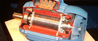
It is obvious that the operating modes of asynchronous electric motors directly depend on their design and general operating principles. This power unit combines two key components:
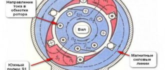
- Fixed stator. A lamellar cylinder in which a wire winding is placed in longitudinal grooves on the inner surface,
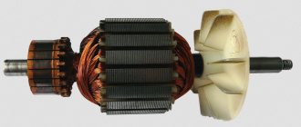
- Rotating rotor. A core (magnetic core) combined with the shaft, which contains a rod winding on the outside.
Due to the different rotation frequencies of the stator and rotor, an EMF arises between them, which sets the shaft in motion. The standard value of this parameter can reach 3000 rpm, which requires a certain effort to stop it. From logical considerations, we can conclude that since the engine starts due to EMF, then it also needs to be stopped electrodynamically.
What is dynamic braking?
At this point, a logical question may arise: why invent something if you can disconnect the engine from the mains and it will stop on its own? This is undoubtedly true, but given the high rotation speed and mass-centering characteristics, it will take some time until the rotor comes to a complete stop. This period is called free run and everyone observed it in childhood, launching a simple spinning top. However, if the operation of the equipment involves frequent use of starters, then this mode leads to an obvious loss of time.
To quickly stop, braking modes are used, which involve the transformation of mechanical (in this case, kinetic) energy artificially. Everyone distinguishes two main types of inhibition, which are then divided into subtypes:
- Mechanical. The engine shaft communicates physically with the brake pads, resulting in friction, rapid stopping and heat generation,
- Electric. An asynchronous motor is stopped by converting the connection circuit, as a result of which mechanical energy is first transformed into electrical energy. Then there are two possible options for its consumption, depending on the circuit: either excess electricity is released into the backup circuit of the network, or it is transformed into heat due to heating of the windings and resistance.
Dynamic braking of an asynchronous motor is of the electrical type, since during the process the stator winding is disconnected from the AC network (two of the three phases) and transferred to a closed DC circuit. In this case, the magnetic field in the stator is converted from rotating to stationary. An EMF will still be induced in the rotor, but the torque will be directed in the opposite direction, which leads to braking.
The classic scheme, as can be seen in the illustration, involves disconnecting one phase from the network using the KM1 contactor. In this case, the other two phases, due to the KM2 contactor, are switched into a circuit with direct current through a diode bridge.
The main advantage of this method of braking is the ability to smoothly control the braking torque (by changing the voltage or resistance) and carry out an accurate stop.
Main types of dynamic braking
Organizing a forced stop of an asynchronous motor using the electrical principle can be carried out in several ways:
- Electrodynamic. This is a classic option, in which two phases need to be short-circuited and transferred to DC power,
- Regenerative (generator). Characterized by the return of excess electricity to the network,
- Anti-inclusion. This option is implemented using a reverse circuit, that is, with the phases connected through a pair of magnetic starters,
- Self-excitation. By connecting a battery of capacitors to the stator windings.
Calculation and selection of braking resistors for frequency converters
The article discusses the methodology for calculating and selecting braking resistance (braking resistor) for frequency converters (inverter, frequency converter), using the example of stopping an AIR type asynchronous motor.
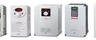
Braking resistors are necessary elements of systems with heavy braking conditions (stopping a large load in a short time), if they contain frequency converters with an intermediate DC link (for example, GA700, GA500, A1000, L1000, J1000 series).
YASKAWA frequency converters GA700 and GA500
series Examples of such systems are:
- Elevators, escalators.
- Various cranes and lifting mechanisms.
- Machine spindles.
- Conveyors and workpiece feeding systems.
Examples of applications where braking resistors are required
Braking resistor calculation example
As an example, consider the operation of a GA700 series frequency converter (model CIPR-GA70C4208) with an AIR 280 M6 engine with an operating cycle of 90 seconds and a braking time of 4 seconds (the stop is made from the rated rotation speed to 0). The motor is connected to the mechanism directly (without a gearbox), and the total moment of inertia is 38 kg * m 2.
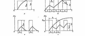
Cyclogram of work with the engine braking section.
From the cyclograms you can see how much the torque value increases when moving into the negative region during braking.
If measures are not taken to utilize the energy that enters the inverter during braking of the electric motor, the inverter will turn off due to an overvoltage error on the DC link (YASKAWA code OV). And in the case of a large inertial load on the electric motor shaft, the DC link capacitors (DCL) may fail.
To utilize the resulting energy, either braking resistors are used, converting energy into heat, or recuperators are used to return it to the supply network.
To select a braking resistor, we first need to determine the electrical braking power:
Find the rated motor speed in rad/s:
w nom = 2p * n nom / 60 = 2p * 968 / 60 = 101.3 [rad/s]
We calculate the maximum moment for a complete stop for a given cycle. If the mechanics includes several kinematic units (for example, gearboxes, drums, etc.), then in the total moment of inertia these units must be brought to the motor shaft:
M max = J ∑ * (w start – w end ) / t brake = 38 * (101.3 – 0) / 4 = 962.35 [N * m]
We determine the maximum power when braking:
P max = M max * (w start – w end ) = 962.35 ´ (101.3 – 0) = 97486 [W]
Determine the electrical braking power. Since there is no gearbox, we take its efficiency value equal to 100%:
P electric brake = (P max – k * P motor ) – ((1 – h ed ) * P max )= (97486 – 0.05 * 90000) – ((1 – 1) * 97486) = 92986 [W]
Here k
– auxiliary coefficient depending on the rated power of the engine:
| Pnom motor, kW | k |
| up to 1.5 | 0,25 |
| from 2.2 to 4.0 | 0,20 |
| from 5.5 to 11 | 0,15 |
| from 15 to 45 | 0,08 |
| above 45 | 0,05 |
We calculate the permissible resistance of the resistor:
R max = U
2 ZPT / P electric brake = 760 2 / 92986 = 6.2 [Ohm]
will have the following values depending on the voltage at the inverter input:
Classic dynamic braking
The effectiveness of this operating mode depends on the calculation and value of the following parameters:
- The amount of current that is supplied through a parallel circuit to the stator windings. The higher this indicator, the greater the braking torque,
- The amount of resistance that is introduced into the rotor circuit. The higher the calculated resistance, the faster the engine decelerates,
- The magnitude of the magnetic driving force (MDF). Sometimes it is called ampere turns, since the calculation is carried out using the formula F = I × W, where I is the current value and W is the number of turns.
The stator winding can be connected in at least five different ways:
- Triangle,
- Triangle with shorted phases,
- A star
- A star with a short-circuited zero,
- A star with two phases shorted.
In each case, based on the vector diagram, the MMF, braking resistance and circuit voltage are calculated.
Regenerative braking
Regenerative braking mode
Since the excess electricity released during braking is sent back to the network through the bridge/capacitor bank, this mode of operation is considered the most economical. Most often, this method is used in lifting and transport equipment and equipment that works to move loads or its own weight downhill. A classic example is an elevator, where regenerative braking from the drive motor is used for initial braking. Also, a similar scheme is widely used in electrified transport, for example, in trams, trolleybuses, and electric trains. It is also used in special equipment, for example, excavators, widely used in the construction of bridges, roads, buildings, etc.
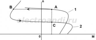
The principle of calculation and organization of the generator mode is that the rotor speed exceeds its synchronous value. In this case, the electromagnetic torque changes direction, which leads to braking.
Regeneration mode in asynchronous electric machines
The recuperation mode is used not only in DC motors. It can also be used in asynchronous motors.
However, this mode is possible in the following cases:
- If you change the frequency of the supply voltage using a frequency converter. This is possible provided that the asynchronous electric motor is powered from a device with the ability to regulate the frequency of the supply network. The braking effect occurs when the frequency of the supply voltage decreases. In this case, the transition to generator mode occurs when the rotor rotation speed becomes higher than the nominal (synchronous) one.
- Asynchronous machines, which are structurally capable of switching windings to change speed.
- In lifting mechanisms where power descent is used. An electric motor with a wound rotor is mounted in them. In this case, the speed is adjusted by changing the value of the resistor connected to the rotor windings. The magnetic flux begins to overtake the stator field, and the slip becomes greater than 1. The electric motor switches to generator mode, the generated electricity returns to the network, and a braking effect occurs.
Back braking
Back-up braking circuit
In practice, the opposition regime can be organized in several different ways. The classic method is to use a pair of magnetic starters connected in a reverse circuit. In this case, a quick stop of the unit is carried out by changing the position of the phases (counter-switching).
The main starter KM2 disconnects the motor M from the network. After this, the parallel starter KM1 turns on the engine again, changing the extreme phases in places, that is, forcing it to rotate in the opposite direction. To prevent excessive overheating, additional resistance can be introduced into the circuit. Also, a counter-connection circuit can be implemented if the engine is used as a brake for a load.
Options for constructing electric brakes
Let's consider several options for braking motors electrically, which can be applied in practice. At the same time, we note the possibility of using braking mechanisms in relation to electric motors of different types. The list of braking techniques considered includes the following:
- countercurrent,
- DC input,
- electronically,
- supersynchronous speed,
- in other ways.
Self-excitation inhibition
Self-excitation braking circuit
This option is implemented by connecting the stator windings to a parallel capacitor bank or bridge (the capacitance will have to be calculated). When the motor is disconnected from the network and the coasting mode must occur, the fading magnetic field begins to power the capacitors, and through them returns back to the winding, creating a braking torque.
As you can see, in practice, a whole range of specific operating modes of asynchronous motors is used, which can be used to quickly and accurately stop it. With frequent starts and stops, dynamic, regenerative, reverse (on starters) or capacitor braking (through bridge or battery calculation) can increase the efficiency of equipment operation and reduce time loss.
Example with electromagnetic stopper
Modern industry produces various versions of electric motors with brakes. Motors with electromagnetic brakes are usually installed on equipment that requires instantaneous stopping. This has found quite wide application for work on machines and conveyors, where compliance with safety regulations plays an important role.
In practice, these are ordinary industrial asynchronous electric motors, the peculiarity of which is their length (the equipment is encased in a special casing).
The first method is suitable for cases where the response time is not important. When the voltage supply is stopped due to the induced magnetic field, the coil current gradually decreases
A slow decrease in the magnetic field leads to a slow increase in braking torque and a long brake response time.
The second option is used where many operations and precise positioning of the electric drive are required. At the moment the current between the coil and the rectifier is interrupted, a fairly rapid decrease in the magnetic field is obtained. The braking torque increases quickly and, accordingly, the brake is applied almost instantly.