Starting current and its multiplicity
To move (start) the engine, you need a huge starting current (Ip). Enormous - compared to the rated (operating) current In at steady speed. Articles usually indicate that the starting current exceeds the operating current by 5-8 times. This number is called “Starting current multiplicity” and is designated as coefficient Kp = Ip / In.
Starting current is the current that the electric motor consumes during starting. You can find out the starting current by knowing the rated current and the Kp coefficient:
Iп = Кп · In
The rated current is always indicated on the motor nameplate:
Rated motor current for different voltages and circuits
Gearbox is an operating parameter that is indicated in the engine characteristics, but it is never indicated on the engine body.
I note that there is no need to confuse rated and operating currents. The rated current is the current at which the motor can operate for a long time; it is limited only by heating the stator winding. The operating current is the real current in a given unit; it is always less than or equal to the rated one. In practice, operating current is measured using a clamp meter, ammeter or current transformer.
If the operating current is greater than the rated current, expect trouble. Read my article about how to protect an electric motor from overload and overheating.
Multiplicity of starting current. It is usually not on the nameplate, but it is present in the documentation and on manufacturers’ websites:
Engine parameters. Starting current ratio
Example from the first line in the picture: a specific 1.5 kW motor has a rated current of 3.4 A. This means that the starting current at some point (how long this “moment” lasts - we’ll look at it below) can reach a value of 3.4 x 6 .5 = 22.1 A!
Judging by the catalogs (they can be downloaded at the end of the article, as usual with me), the starting current exceeds the rated current in the range from 3.5 to 8.5 times.
The starting current multiplicity depends primarily on the engine power and the number of pole pairs. The lower the power, the lower the starting current. And the fewer pairs of poles (the higher the rated speed), the greater the starting current.
That is, high-speed motors (3000 rpm, 1 pair of poles) of relatively high power (more than 10 kW) have the highest starting current (7 - 8.5 of the nominal value).
This happens because the current consumption and moment of inertia at start-up depend on the design of the motor and the winding method. Few poles - low winding resistance. Low resistance - high current. In addition, high-speed engines require more time to fully rev up, and this is again a difficult start.
To explain it in more scientific language, it goes like this. When the engine is stationary, its slip degree S = 1. When spinning up (or, as experts like to say, unwinding), S tends to zero, but never reaches it - that’s why the motor is called asynchronous, because the rotation of the rotor will never catch up with the rotation of the stator field due to losses. At the same time, the rotor core is saturated with a magnetic field, the self-induction emf and inductive resistance increase. This means the current decreases.
For those who want to know more, at the end of the article I have posted several good books on the topic.
In fact, it’s not that simple, let’s start digging deeper.
Design features
Knowledge of the design features of any equipment greatly facilitates the purchase and subsequent work with it, including the operation and repair of an asynchronous motor with a wound rotor. First of all, you should remember that all electric motors are designed according to a similar principle - they necessarily have a stationary stator and a movable rotor that carries out rotational movements inside the power unit. The stator of an asynchronous motor with a wound rotor has windings connected to the AC mains, the voltage on which interacts with the rotor windings. This connection is explained by the principles of magnetic flux.
The usual design of the stator of an asynchronous motor is an electric motor housing with a core pressed inside. The core winding is divided into several sectors enclosed in coils. Cables with protective insulation are removed from these windings, preventing their mutual short circuit. The rotor is made of a shaft and an assembled lamellar core. Typically, plates with standard size symmetrical grooves made of high-tech steel are used here. During operation of the rotor shaft, torque is transmitted to the drive of the electrical installation.
A drawing of an asynchronous motor with its main components looks like this:
The most common are two types of rotors:
- Short-circuited.
- Phase.
The first option, as part of its design, has aluminum rods passing through the core and closed by end rings. This is the so-called “squirrel wheel”. To increase the strength of the grooves, they are also often treated with an aluminum compound. The design of a wound rotor is somewhat different from that of a squirrel-cage rotor. Here, the number of coils installed at a certain angle directly depends on the number of paired poles, in many cases comparable to the paired poles found on the stator.
How to find out the starting current?
The starting current multiplicity (the ratio of the starting current to the rated current) is not so easy to find in the engine documentation. But you can measure (evaluate, find out) yourself. Here are a few ways off the top of your head:
- The first way (the best for theoretical study) is to use an oscilloscope. Take a shunt (for example, a 0.1...0.5 Ohm resistor, the smaller compared to the windings, the better), and look at the oscillogram on it at the time of start-up. Next, from the maximum amplitude value, we determine the effective voltage (divide by the root of 2), then, according to Ohm’s law, we calculate the starting current. You don’t have to multiply or divide anything - just measure the current with clamps in operating mode, and multiply it by the difference in currents on the oscilloscope screen. The good thing about this method is that you can see transient processes caused by self-induction emf, instantaneous current values, and acceleration duration. In addition, the parameters of the supply network are taken into account. Another plus is that the starting current is measured real, on a real engine and mechanism.
- The second way to measure the starting current is to apply a reduced (5-10 times) operating frequency voltage to the motor and measure the current. Why reduced? This is necessary so that the rotor can be easily fixed without overheating. Recalculate the measured current to obtain the starting current. It is enough to measure the current in one phase. For others, the currents will be (must be) the same. This method is used in the production and testing of engines. It is in this way that manufacturers obtain tabular data. The method is based on the rated current; in reality (on a real mechanism) the starting current may be different!
- Measure the starting current with a clamp meter. The advantage of this method is simplicity and efficiency. Pincers are used in most cases to check engine operating conditions. The downside is that such pincers are quite inertial, and we need to see what is happening in a split second. But this minus is leveled out when we measure the current when starting a load with a high moment of inertia (fans, pumps with massive impellers). The start-up lasts more than 10 seconds, and everything is visible on the ticker screen. I will add that there are clamps with the Inrush function that can measure the inrush current from 0 to maximum during an integration time of about 100 ms.
- Current transformer. This is used, for example, in electricity metering units - thanks to the current transformer, there is no need to measure the real current, but you can measure the current reduced by a precisely known number of times. They also measure current in electronic starting devices (frequency converters, soft starters). The disadvantage of this method is that the current transformer is designed for a frequency of 50/60 Hz, and transient processes during startup have a wide spectrum and many harmonics. Therefore, we can say that this method also has high inertia.
Of course, reality is different from experiment. First of all, the short circuit current of a real power supply network is not infinite. That is, the wires supplying the engine have a resistance at which the voltage drops at the moment of starting (sometimes by up to 50%). Because of this limitation, the actual starting current will be less and acceleration will take longer. Therefore, you need to understand that the value of the starting current multiplier specified by the manufacturer will always be less in reality.
What are engines for - to power machinery and make a profit!
Now let's look at another question -
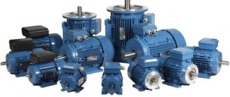
Application
Today, most of the motors produced on an industrial scale are of the asynchronous variety.
Due to a number of advantages that machines with wound rotors have, they are widely used in various areas of human activity, including to support work:
- Automation devices and devices from the telemechanical field.
- Household appliances.
- Medical equipment.
- Equipment designed for audio recording.
What is the harm from inrush current?
Inrush current is a problem. This -
- overload of the supply network, leading to heating (up to the contacts burning out) and voltage sags;
- excessive wear, overload and overheating of the engine; some manufacturers indicate among the engine parameters the maximum number of starts per hour or per day - precisely because of overheating;
- wear and overload of the mechanical drive (bearings, gearboxes, belts), especially those with a large moment of inertia,
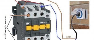
- interference caused by the activation of contactors, which are transmitted not only through wires, but also through an electromagnetic field,
- problems with technology - many processes cannot be started abruptly.
The starting current overloads everything, and the moment of starting becomes a burden to all participants in the process. It is at this critical moment that a “weak link” may appear. In addition, many power participants operating on this network experience problems - for example, light bulbs dim due to low voltage, and controllers can freeze due to strong interference.
And at the same time, starting current is a problem that cannot be avoided if you immediately supply the motor with rated power and do not use special methods.
So let's figure it out
What is the difference between this parameter and the car battery charging current?
The starting current is a value that exclusively affects the start of the power unit, and the charging current of the car battery, in turn, determines the level of potential required to charge the battery itself.
It is worth noting that there are three main ways to charge the battery in a car:
- charging current with constant amperage;
- charging with constant voltage current;
- mixed method with a stable current and fluctuating voltage at the beginning of charging and a flat voltage and regressing current at the end of the process.
It should be noted that the mixed method is the most effective and prolongs the life of your energy carrier.
How to reduce the starting current of an asynchronous motor
The problem of high inrush current can be solved electrically in two ways:
- First, apply a reduced voltage to the motor, and then, as it accelerates, increase the voltage and rotation speed to the nominal value. This method is used in electronic engine starting devices - soft starters (soft starters) and frequency converters (frequency converters).
- Use starting current limiters when, when starting, the engine is powered through powerful resistors, and then switches to nominal using a timer. The resistance of the resistors is commensurate with the resistance of the starter winding (units of Ohm, depending on the power). This device is easy to make yourself (contactor + time relay).
- Immediately apply full voltage, but first connect the windings in such a tricky way that the engine does not spin up to full power. And only when in this mode the engine spins up as much as possible, turn it on at full speed. This scheme is called “Star - Triangle”, read the next article.
You can design some kind of clutch, gearbox, variator - in order to spin the engine idle, and then connect a mechanical torque consumer.
In modern equipment, motors more powerful than 2.2 kW are almost never directly switched on, so inrush currents do not play a role for them. To reduce the starting current (and not only), frequency converters are mainly used, which will be discussed in separate articles.
Calculation of electric motor power for a pump
The choice of electric motor for a pumping installation depends on specific conditions, first of all, on the water supply scheme. In most cases, water is supplied using a water tank or a water boiler. Centrifugal pumps with asynchronous motors are used to drive the entire system.
The selection of the optimal pump power is carried out depending on the need for fluid supply and pressure. The QH pump flow is measured in liters delivered per hour and is designated as l/h. This parameter is determined by the following formula: Qn = Qmaxch = (kch x kday x Qav.day) / (24 η), where Qmaxch is the possible maximum hourly water flow rate, l/h, kch is the coefficient of unevenness of hourly flow, kday is the coefficient of unevenness daily flow rate (1.1 - 1.3), η - efficiency of the pumping unit, taking into account water losses), Qavg.day - value of the average daily water flow rate (l/day).
How to reduce harm from inrush current?
If it is impossible to change the engine power supply circuit (for example, a neighbor in the country starts a lathe every half hour, and no “methods of influence” have any effect), then various methods can be used to minimize harm from starting currents. For example:
- Install an inverter UPS (UPS) for important consumers or for the entire house, which will keep the voltage normal in any situation. The most expensive but effective way.
- Install a voltage stabilizer. But keep in mind that not all stabilizers are equally useful. Sometimes they may not cope, and sometimes they may even make the situation worse. For more details, follow the link provided.
- If the power supply is single-phase, then you can try switching from the “bad” phase to the “good” one. Sometimes this method is as effective as using a teleport instead of the Taganrog-Moscow bus.
But I remind you that we are not dealing with eliminating consequences, but preventing problems, so let’s move on.
Conclusions:
- When calculating the total power of electrical equipment, the power of devices with starting currents must be calculated not at nominal value, but taking into account the starting currents (in W or A).
- Inrush currents are provided by equipment whose design includes an electric motor, pump, compressor, filament or inductor.
- The worse the voltage in the main wire (below 150 V or above 250 V), the higher the rating of the stabilizer or UPS should be (about 30% more than the total power of the operating equipment).
Inrush currents can be associated with the start of a bicycle's movement: when it starts to move, it takes a lot of force to spin the wheels, but once the bicycle starts moving, less force is required to maintain speed.
Operating time and starting current value
The duration of the starting current will be considered the time during which the current decreases from the maximum (Iп) to the nominal value (Iн). This duration is actually equal to the acceleration time from zero to the rated rotation speed.
The whole question is what is the duration of this current - 10 milliseconds (half a period) when the engine is idling, or 10 seconds when there is a massive impeller on the shaft. Theoretically, it is impossible to calculate this time. However, I will share some thoughts.
As I said above, the motor current at start-up can exceed the norm several times (Kp). And some novice electricians who do not read my blog believe that the circuit breaker should be chosen in the same way - for a higher current. In articles and even instructions they write that “When choosing a machine, it is necessary to take into account that the starting current of an asynchronous electric motor is 5 - 7 times higher than the rated one.” How to take this into account? Is it really possible to choose the current of the machine 5-7 times higher than the rated current of the motor?
Example:
Nameplate of a Chinese electric motor 30 kW
Written – 56 A. What does this mean? Is it really true that the current of the circuit breaker should be more than 300 A? Of course not. And the choice of machine in this case depends not only on the rated current of the motor (56 A), but also on the duration of the starting current.
By the way, let's investigate and find out the starting current of this motor. After all, we are not destined to get to the website of this Chinese manufacturer. Initial nominal data: power - 30 kW, torque - 190.9 N m, current - 56 A. We look at the catalogs of domestic manufacturers, looking for a similar engine, because the laws of physics are the same in both Russia and China. We find (catalog at the end of the article): this is a 1500 rpm motor, 4 poles, with a starting current multiplicity Kp = 7. As a result, we get: Iп = In · Kp = 56 · 7 = 392 A. This is a theoretical starting current, but it is not machine setting current!
The starting current is the maximum possible current . The maximum current will be at start-up, that is, when the engine is stopped. That is, the starting current is ALWAYS present, and its initial value is always prohibitive. In the case of our Chinese engine - 392 A, if we take the short-circuit current of the supply network equal to infinity (voltage source with zero internal resistance).
Motor protection circuit breaker - how to choose the right one?
When selecting circuit breakers that can protect electric motors from damage as a result of short circuits or excessively high loads, it is necessary to take into account the large value of the starting current, often 5-7 times higher than the nominal value.
Asynchronous power units with a squirrel-cage rotor are subject to the most powerful starting overloads. Since this equipment is widely used for work in industrial and domestic conditions, the issue of protecting both the device itself and the power cable is very relevant.
This article will discuss how to correctly calculate and select a motor protection circuit breaker.
Tasks of devices for protecting electric motors
Household electrical equipment is usually protected from large inrush currents in networks using three-phase circuit breakers that operate some time after the current exceeds the rated value.
Thus, the motor shaft has time to spin up to the desired rotation speed, after which the force of the electron flow decreases. But the protective devices used in everyday life do not have precise settings.
Important
Therefore, the choice of a circuit breaker that allows you to protect an asynchronous motor from overloads and short-circuit overcurrents is more complicated.
Modern motor protection circuit breakers are often installed in a common housing with starters (the so-called motor starting switching devices). They are designed to perform the following tasks:
- Protecting the device from overcurrent occurring inside the motor or in the power supply circuit.
- Protection of the power unit from phase conductor breakage, as well as phase imbalance.
- Providing a time delay that is necessary so that the motor, which is forced to stop as a result of overheating, has time to cool down.
Control and protective automation for the engine on video:
- Shutting down the installation if the load is no longer supplied to the shaft.
- Protection of the power unit from long overloads.
- Protection of the electric motor from overheating (to perform this function, additional temperature sensors are mounted inside the unit or on its body).
- Indication of operating modes, as well as notification of emergency conditions.
It is also necessary to take into account that the circuit breaker for protecting the electric motor must be compatible with control and control mechanisms.
Calculation of an automatic machine for an electric motor
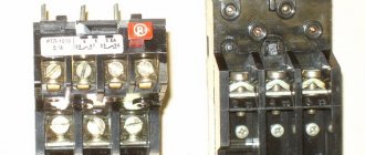
Until recently, the following scheme was used to protect electric motors: a thermal regulator was installed inside the starter, connected in series with the contactor. This mechanism worked like this.
When a large current passed through the relay for a long time, the bimetallic plate installed in it was heated, which, bending, interrupted the contactor circuit.
If the excess of the set load was short-term (as happens when starting the engine), the plate did not have time to heat up and trigger the machine.
Internal structure of the motor protection circuit breaker in the video:
The main disadvantage of this scheme was that it did not save the unit from voltage surges, as well as phase imbalance. Nowadays, the protection of electric power plants is provided by more accurate and modern devices, which we will talk about a little later. Now let’s move on to the question of how to calculate the machine that needs to be installed in the electric motor circuit.
To select a protective circuit breaker for an electrical installation, you need to know its time-current characteristics, as well as its category. The time-current characteristic does not depend on the rated current for which the AV is designed.
To prevent the circuit breaker from tripping every time the motor is started, the value of the starting current should not be greater than that which causes the device to immediately operate (cut-off). The ratio of the starting current and the nominal value is specified in the equipment passport, the maximum allowable is 7/1.
Advice
When calculating the machine practically, you should use the reliability coefficient, denoted by the symbol Kn. If the rated current of the device does not exceed 100A, then the value of Kn is 1.4; for larger values it is 1.25. Based on this, the value of the cut-off current is determined by the formula Iots ≥ Kn x Istart. We select the circuit breaker in accordance with the calculated parameters.
Another value that must be taken into account when selecting when the machine is mounted in an electrical panel or a special cabinet is the temperature coefficient (CT). This value is 0.85, and the rated current of the protective device should be multiplied by it when selecting (In/Kt).
Modern electrical protection devices for power units
Modular automatic motors, which are universal devices that successfully cope with all the functions described above, are very popular.
In addition, they can be used to adjust shutdown parameters with high accuracy.
Modern automatic motors come in many varieties, differing from each other in appearance, characteristics and control method.
As when selecting a conventional device, you need to know the value of the starting current, as well as the rated current. In addition, it is necessary to decide what functions the protective device should perform. Having made the necessary calculations, you can buy an automatic motor.
The price of these devices directly depends on their capabilities and the power of the electric motor.
Features of protection of electric motors in industrial conditions
Often, when turning on devices whose power exceeds 100 kW, the voltage in the general network drops below the minimum.
In this case, the working power units are not switched off, but their speed is reduced. When the voltage is restored to normal levels, the motor begins to gain speed again.
In this case, its operation occurs in overload mode. This is called self-starting.
Self-starting sometimes causes false alarms.
This can happen when, before the temporary voltage drop, the installation had been operating in normal mode for a long time, and the bimetallic plate had time to warm up.
note
In this case, the thermal release sometimes trips before the voltage returns to normal. An example of a voltage drop in a car's electrical network in the following video:
To prevent the shutdown of powerful factory electric motors during self-starting, relay protection is used, in which current transformers are connected to the general network. Protective relays are connected to their secondary windings. These systems are selected using complex calculations. We will not present them here, since in production this task is performed by full-time power engineers.
Thermal effect of starting current
If we move on to the formulas, the starting current has a thermal effect on the electric motor, which is described by the so-called Joule integral. Simply put, the thermal energy produced by an electric current is proportional to the square of the current multiplied by the time. This quantity is denoted by I2t.
The good news is that the circuit breaker has approximately the same thermal (time-current) characteristic as the time-current characteristic of motor acceleration.
Compare:
Time-current characteristics of the circuit breaker
What do we see? To protect the engine, automatic machines with characteristic D are mainly used, precisely in order to react less to short-term overloads. Read more here.
And for the motor starting current the graph will be something like this:
Starting current graph (theoretical) at Kp = 6
The linearity of the graph is conditional. It all depends on the change in load torque during acceleration. The theoretical graph is shown with a dotted line. On this graph Kp = Ip / In = 6, but this is a theoretical (tabular) value. Acceleration time to nominal = tп.
The actual graph is drawn with a solid line. On it Iп` is the real value of the starting current, which is always less than the theoretical one. This is due to the fact that the supply network has non-zero resistance, and as the current increases, voltage losses occur on the wires.
I wrote about losses at low voltage here, and about losses in 0.4 kV networks here.
It is clear that due to losses, the acceleration time will be longer; it is indicated on the graph by tп`.
Now let's rotate the last graph to bring the axes to the same coordinate system:
Time from current, so to speak
Isn’t it very similar to the time-current characteristic of a protective motor?
It turns out that both characteristics compensate each other, and when choosing a machine, it is enough to adjust its setting to the rated current of the motor. For particularly difficult starts, when the area under the motor starting curve is greater than the area under the curve of the circuit breaker, it is worth thinking about a soft start - soft starter or inverter.
Determining the possibility of starting an electric motor
When designing, it is sometimes necessary to check whether a squirrel-cage motor can be started under given electrical network parameters. It is better to provide a soft starter or a frequency converter, but an electromagnetic starter is cheaper.
The testing technique boils down to assessing the voltage drop from the transformer to the electric motor.
The problem is that when starting, the motor receives a starting current that is 4-8 times the rated current.
The starting current creates an additional voltage loss in the network, and this can lead to the fact that the motor will not be able to crank the shaft with a load, since the torque developed by the motor changes in proportion to the square of the voltage. In addition, as a result of a sharp drop in voltage, other electric motors powered from this network may stop.
Normal engine starting is possible if the initial torque of the electric motor is 10% greater than the starting torque of the resistance of the driven mechanism.
To check engine starting, a sufficient condition is to compare the starting (initial) torques of the electric motor and the driven mechanism.
Engine starting condition
where Uд is the voltage at the electric motor terminals at the initial moment of start-up in fractions of the rated voltage;
mp=Mstart/Mnom – multiplicity of the starting torque of the electric motor at the rated voltage at its terminals (according to the catalogue);
mmech=Mmech/Mnom – required multiplicity of starting torque of the driven mechanism;
Кз – load factor of the electric motor;
1,1 – safety factor;
dUadd% - additional voltage losses (%) in the network from the supply transformer and in the transformer to the terminals of the electric motor of the mechanism;
Ki – multiplicity of starting current at rated voltage at the motor terminals (according to the catalogue);
Inomd – rated current of the electric motor (according to the catalogue), A;
Unom – rated voltage of the transformer;
rtr, xtr – active and inductive resistance of the transformer, related to the low voltage winding;
r, x – active and inductive resistance of the cable line;
cosfnom – nominal value of power factor;
mp=Mstart/Mnom – multiplicity of the starting (initial) torque of the electric motor (according to the catalogue);
snom – nominal slip;
dUс% - total voltage loss in the line from the busbars of the supply transformer to the engine of the mechanism and in the transformer without taking into account the engine start (%);
dUс=0.08 Unom – in the absence of data on the power of transformers and their loading;
When determining mmech, you can be guided by the following data:
Fans – 04-0.5.
Centrifugal and piston compressors – 0.4.
Centrifugal and cargo pumps – 0.4.
Metalworking machines – 0.3.
Elevators – 1.7-1.8.
Other electric motors will operate stably when the voltage from the start of another electric motor decreases, if the maximum torques remain greater than the torques of the driven mechanisms.
Running another engine
mmax=Mmax/Mnom – multiple of the maximum torque of the electric motor (according to the catalogue).
By substituting the values in these formulas, we find out whether the supply network with the transformer can withstand starting the engine, and we can also check whether another running engine will turn off at this moment.
In the near future I plan to create a program based on these formulas for quickly checking the start of an electric motor. There is no point in checking low power engines. Somewhere it was mentioned the ratio of the transformer power to the motor power at which this check should be performed (I’ll find it and write it).
Important
On the forum I posted a program to check the possibility of starting an engine, but there were some problems with the fonts. You may be able to run it, since it is made under DOS.
Source: https://220blog.ru/pro-raschet/opredelenie-vozmozhnosti-puska-elektrodvigatelya.html
Real current measurements
As I said above, in my opinion the best way to “see” the inrush current is to use an active (resistive) shunt and look at the voltage on it with an oscilloscope.
I use this shunt:
Shunt for measuring inrush current using an oscilloscope
The subject is a geared motor that turns a vertical auger through a chain transmission:
Geared motor on which we measure the starting current
The auger was full at the time of start-up, so its operating current (7.7 A, measured with clamps) was almost equal to the rated current (8.9 A, visible on the nameplate).
Vertical auger motor nameplate
The inrush current situation is visible on the oscilloscope:
Inrush current waveform 500 ms/div
Let's bring the moment of interest closer by accelerating the scan to 100 ms/div:
Inrush current waveform 100 ms/div
Here it is already easy to see the sine of the supply current and estimate the multiplicity factor of the starting current Kp, which is approximately equal to 4.
Let's bring the moment of truth even closer (up to 50 ms/div):
Motor starting moment – starting current
Here the transient processes caused by the inductance and self-inductive emf of the motor windings are already clearly visible. This pulse, the duration of which is much less than the network period of 20 ms, provides good interference with a wide spectrum into the power supply network and radio air.
Another reason to use an inverter? Not really, the situation with interference there is much worse!
For those who don’t want to bother, I repeat – there are clamps with the Inrush function that can measure inrush current.
Examples of rated power and starting power of household appliances
| Duration of starting currents, s | Coefficient at start-up | Example of a stabilizer model, VA | UPS model example | |
| Fridge | 4 | 3 | "Calm" R1200 / Progress 1500T | N-Power Pro-Vision Black M 3000 LT |
| Washing machine | 2500 | Progress 3000T | ||
| Microwave | 1600 | 2 | "Calm" R2000 | |
| Air conditioner | Progress 5000L | |||
| Vacuum cleaner | 1500 | 2 | Progress 3000T | |
| Food processor | 7 | Progress 2000T | ||
| Dishwasher | 2200 | 3 | Progress 3000L | |
| Submersible well pumps, deep well pumps | 2 | Progress 3000L | DPK-1/1-3-220-M | |
| Circulation pumps | "Calm" R 600 ST | Inelt Intelligent 500LT2 | ||
| Incandescent lamp | 100 | 0,15 | high precision L series |
The table does not reflect the exact values of electrical appliances; only approximate figures are provided for understanding the algorithm for choosing a voltage stabilizer and UPS.
Source: stabmart.ru
Download
I hope readers will forgive me for my free explanation of the processes - I tried to explain everything “on the fingers”. Who needs academic knowledge, please:
• V.L. Likhachev. Asynchronous electric motors. 2002 / The book is a reference book that describes in detail the design, operating principle and characteristics of asynchronous electric motors. Reference data is provided for engines of previous years of production and modern ones. Electronic starting devices (inverters), electric drives are described., djvu, 3.73 MB, downloaded: 7136 times./
• Bespalov, Kotelenets - Electrical machines / Transformers and electrical machines used in modern technology are considered. Their decisive role in the generation, distribution, conversion and utilization of electrical energy is shown. The basic theory, characteristics, operating modes, examples of designs and applications of electrical generators, transformers and motors are given., pdf, 16.82 MB, downloaded: 2317 times./
• MM. Katzman - Electrical Machines / Some say this is the best textbook on electrical engineering. The book discusses the theory, principle of operation, design and analysis of operating modes of electrical machines and transformers, both general and special purpose, which have become widespread in various branches of technology., pdf, 22.12 MB, downloaded: 2061 times./
• Electromash motor catalog / Asynchronous electric motors with squirrel-cage rotor - manufacturer’s catalog, pdf, 3.13 MB, downloaded: 1376 times./
• VEMZ engines catalog / Engine parameters and catalogue, pdf, 3.53 MB, downloaded: 1181 times./
• Dyakov V.I. Typical calculations for electrical equipment / Practical calculations for electrical equipment, theoretical information, calculation methods, examples and reference data., zip, 1.53 MB, downloaded: 2515 times./
• Karpov F.F. How to check the possibility of connecting several motors to the electrical network / The brochure shows the calculation of the electrical network for voltage fluctuations during the start-up and self-starting of asynchronous motors with squirrel-cage rotor and synchronous motors with asynchronous starting. The conditions under which starting and self-starting of engines are permissible are considered. The presentation of calculation methods is illustrated with numerical examples. The brochure is intended for qualified electricians as a guide when choosing the type of electric motors connected to a municipal or industrial power supply network., zip, 1.9 MB, downloaded: 1640 times./
• Operating manual for asynchronous motors / This manual contains the most important instructions for transportation, acceptance, storage, installation, commissioning, operation, maintenance, troubleshooting and troubleshooting for electric motors produced by Elektromashina. The operating manual is intended for three-phase asynchronous electric motors of low and high voltage series A, AIR, MTN, MTKN, 4MTM, 4MTKM, DA304, A4., pdf, 7.54 MB, downloaded: 2540 times./
• Catalog of AIR engines / Catalog of AIR engines - power from 0.12 to 315 kW; rotation speed 3000, 1500, 1000, 750 rpm; mains voltage 220/380 V, 380/660 V;, pdf, 1.07 MB, downloaded: 1044 times./
• Lomonosov, V.Yu.; Polivanov, K.M.; Mikhailov, O.P. Electrical engineering. / Lomonosov, V.Yu.; Polivanov, K.M.; Mikhailov, O.P. Electrical engineering. One of the best books on the basics of electrical engineering. The presentation begins with the very basics: it explains what voltage, current and resistance are, provides instructions for calculating the simplest electrical circuits, and talks about the relationship and interdependence of electrical and magnetic phenomena. Explains what alternating current is and how an alternating current generator works. It describes what a capacitor is and what an inductor is, what their role is in alternating current circuits. It is explained what three-phase current is, how three-phase current generators are designed and how its transmission is organized. A separate chapter is devoted to semiconductor devices: it talks about semiconductor diodes, transistors and thyristors; on the use of semiconductor devices for rectifying alternating current and as semiconductor switches. The achievements of microelectronics are briefly described. The last third of the book is entirely devoted to electrical machines, units and equipment: chapter 10 deals with direct current machines (generators and motors); Chapter 11 is devoted to transformers; AC machines (single-phase and three-phase, synchronous and asynchronous) are described in detail in Chapter 12; switches, electromagnets and relays are described in Chapter 13; Chapter 14 deals with electrical diagramming. The last, chapter 15, is devoted to measurements in electrical engineering. This book is a great way to learn the basics of electrical engineering, to understand the fundamental principles of the operation of electrical machines and units., zip, 13.87 MB, downloaded: 2653 times./
Another manual on motors: • Starting and protecting AC motors / Starting and protecting AC motors. Starting and braking systems for AC motors. Protection devices and fault analysis of AC motors. Guide to selecting protection devices. Manual from Schneider Electric, pdf, 1.17 MB, downloaded: 2042 times./
Electric motor power calculation
The conversion of electrical energy into kinetic energy is carried out using various types of electric motors. These devices are widely used in modern production and in everyday life. Most often, electric motors serve as electric drives for machines and mechanisms and are used to ensure the operation of pumping equipment, ventilation systems and many other units and devices. In connection with such a wide application, the calculation of electric motor power is of particular relevance. For these purposes, many different methods have been developed that allow calculations to be performed in relation to specific operating conditions.
How to properly charge the battery?
The charger must be able to output up to 17 volts if the battery operating voltage is 12 volts. Otherwise, you will not be able to charge the battery 100%.
In addition, you need to take into account the battery capacity when choosing the level of the supplied starting current to the car battery, the table of which is presented below. For example, if the battery has a capacity of 70 Ah, then to charge for 10 hours it is necessary to set the current to 7 A. Gradually, the current should be reduced with a parallel increase in voltage. This method will make it possible to fill the battery life more efficiently, since as the charge level increases, the resistance also increases, but the battery’s operation is still aimed at voltage, which is why it should be increased.