Sooner or later, a person interested in electrical engineering hears mentions of a rotor and a stator, and asks the question: “What is this, and what is the difference between these devices?” In simple words, the rotor and stator are the two main parts located in an electric motor (a device for converting electrical energy into mechanical energy). Without them, the existence of modern engines, and therefore most electrical devices based on them, would be impossible. The stator is a stationary part of the device, and the rotor is a movable part; they rotate in different directions relative to each other. In this article, we will analyze in detail the design of these parts and their principle of operation, so that after reading the article, readers of the Sam Electric website will no longer have any questions about this matter.
Asynchronous motor stator
The stator of an asynchronous motor is a core consisting of electrical steel plates and containing copper windings, which are laid in a certain way in the stator grooves.
As mentioned, the stator core consists of plates that are insulated from each other. There are grooves on the inside of the stator
in which the insulation is placed
Next, varnished copper wire is wound into these grooves in a certain way, which represents the stator windings
An induction motor has three “pieces” of copper wire
Which are laid in a certain way in the stator grooves at an angle of 120 degrees relative to each other.
All 6 ends of the winding wires are led out into the terminal box, which is located on the motor housing.
The motor stator, or more precisely, the dimensions of the core, the number of coils in each winding and the thickness of the winding wire from which the coils are wound determine the main parameters of the motor. For example, the rated speed of the engine depends on the number of coils in each winding, and the rated power of the engine depends on the thickness of the wire with which they are wound. The number of windings for a three-phase asynchronous motor is always three. But the number of coils in each of these windings is different. Coils can be wound into one or two wires. Considering that the rated speed of the motor is inversely proportional to the rated load, we can safely say that the shaft speed of an asynchronous motor will decrease as the load increases. If, while the engine is running, its speed begins to decrease due to an increase in load, then not stopping this process can lead to a complete stop of the engine. The engine will begin to hum strongly, the rotor shaft will not spin - the coils will become very hot, followed by destruction of the insulation of the winding wire, which will lead to a short circuit and fire of the windings.
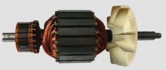
A real photo of the stator of one of the asynchronous motors looks like this.
Restoring winding markings
More precisely, marking the windings is needed only to determine the direction of winding of the winding coils. The end and beginning of the winding are designated for this purpose only. The fact is that when the winding is turned on, eddy currents begin to appear in it, which move in the direction “from beginning to end”. If the windings are connected according to the principle “beginning with beginning, end with end,” then the currents will be summed up, the windings will turn into one large resistor and a huge total current will arise. The engine will start to make a loud noise and will not turn over. The windings will start to heat up very quickly and the motor will burn out. Moreover, it is quite possible that a real flame of orange-blue color will break out with a very harmful and unpleasant odor.
There is a way to determine the ends and beginnings of windings.
This whole process is shown very well in the video. The author of this video used a mains voltage of 220 Volts to test, which I highly do not recommend doing. Use step-down transformers or an autotransformer.
Speed control of asynchronous motors
To regulate the rotation speed of asynchronous electric motors and control their operating modes, the following methods exist:
- Frequency - when the frequency of the current in the electrical network changes, the rotation speed of the electric motor changes. For this method, a device called a frequency converter is used;
- Rheostat - when the resistance of the rheostat in the rotor changes, the rotation speed changes. This method increases the starting torque and critical slip;
- Pulse is a control method in which a special type of voltage is supplied to the motor.
- Switching the windings during operation of the electric motor from a star circuit to a delta circuit, which reduces starting currents;
- Control by changing pole pairs for squirrel-cage rotors;
- Connecting inductive reactance for wound-rotor motors.
With the development of electronic systems, the control of various asynchronous electric motors is becoming more efficient and accurate. Such engines are used everywhere in the world, the variety of tasks performed by such mechanisms is growing every day, and the need for them is not decreasing.
Winding
After all the preparatory work has been completed, the stator is rewinded. In workshops, a special winding machine is used for this. It has a counter for the number of turns and special pads. They give the coils the required shape. At home, you can create similar pads yourself.
The work is performed on a table covered with a soft cloth. This will prevent damage to the insulating varnish. The coil needs to be threaded inside the stator. Next, lay the wire in the grooves, prying them one by one through a special gap.
You can guide the wires using a wooden tool, similar to a dull knife. After laying the coil group, it is tied and a gasket is inserted. The system is fixed using a special peg, which is driven along the entire length of the groove. Next, the same actions are performed with the next coil group.
Stator in different types of electric motors
The stator is an integral component of an electric machine that remains stationary while the engine is running. The rotor is the rotating part of an electric motor that transmits mechanical energy to the output shaft. Another name for a rotor is an armature.
Synchronous or commutator motor
Electric current is transmitted to the commutator lamellas by graphite brushes. Such an electric motor will operate in both direct and alternating current networks. The pulsating magnetic field generated by the stator windings will interact with the pulsating magnetic field generated by the armature windings. The rotor will begin to rotate. Such electric motors are widely used in various household and industrial appliances: electric drills, vacuum cleaners, power drives of machine tools, and electric vehicles.
Interesting. Motors of this type have another name - synchronous. This means that the rotation speed of the rotor is equal to the rotation speed of the electromagnetic field arising in the motor.
Asynchronous motors
The overwhelming majority of electric motors used both in industry and in everyday life are asynchronous electric motors with squirrel-cage rotors. Such motors are used in three-phase and single-phase AC networks.
Asynchronous motor
The stator structure is assembled from a large number of steel plates and is located in a base housing cast from non-magnetic metals: cast iron or aluminum.
Stacked motor stator
Plate material – electrical steel. The plates are insulated from each other with a special dielectric varnish. The stator has longitudinal grooves where three windings are placed, shifted relative to the axis of rotation of the electric motor by 120 degrees from each other. The rotor is also made of insulated electrical steel plates. Rods made of aluminum, less often copper, are placed in the grooves of the rotor, connected at the ends by slip rings. Hence the name - squirrel-cage rotor. This design, called a “squirrel wheel,” plays the role of a rotor winding.
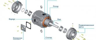
Below is a cross-sectional view of an asynchronous electric motor. You can clearly see what a stacked stator is.
Sectional view of an asynchronous motor
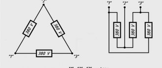
The motor windings can be connected to a three-phase electrical network in a delta or star configuration.
Three-phase motor connection options
The circuit is switched in the motor terminal box, called born or brno.
When three-phase voltage is applied, pulsating currents arise in the stator windings, which cause the appearance of a rotating magnetic field in the stator. This field crosses the conductive rods of the rotor, in which secondary pulsating currents are induced. The result is the appearance of a magnetic field in the rotor. The magnetic fields of the stator and rotor interact and cause the rods of the “squirrel wheel” to rotate, along with the rotor itself. The armature rotates at a speed slightly lower than the magnetic field of the stator.
The magnitude of this difference is called slip and can range from 2 to 8%. Due to the presence of slip, motors of this design are called asynchronous. The sliding effect is physically necessary for the operation of an asynchronous motor - there will be no lag in the rotation of the rotor from the magnetic field of the stator, no current will be induced in the rotor rods, and the magnetic field in the armature causing the rotor to rotate will disappear.
Operating principle of electric motors
Induction motors consist of a rotor and a stator.
The currents in the stator windings are created by the phase voltage, which drives the induction motor. These currents create a rotating magnetic field, also called a stator field. The rotating magnetic field of the stator is determined by the currents in the windings and the number of phase windings.
A rotating magnetic field forms a magnetic flux. The rotating magnetic field is proportional to the electric voltage, and the magnetic flux is proportional to the electric current.
The rotating magnetic field of the stator moves faster than the rotor, which promotes the induction of currents in the windings of the rotor conductors, resulting in the formation of a rotor magnetic field. The magnetic fields of the stator and rotor form their own fluxes, these fluxes will attract each other and create a torque that causes the rotor to rotate. The operating principles of an induction motor are shown in the illustrations on the right.
Thus, the rotor and stator are the most important components of an AC induction motor. They are designed using CAD (Computer Aided Design). Next we will talk in more detail about the design of the rotor and stator.
Single-phase asynchronous electric motors
Device and principle of operation
The power of such a single-phase 220V motor can, depending on the design, range from 5 W to 10 kW. Its rotor is usually a short-circuited winding (“squirrel cage”) - copper or aluminum rods closed at the ends.
Such a single-phase motor usually has two windings offset by 90° relative to each other. The working (main) one occupies most of the stator slots, and the starting (auxiliary) one occupies the remaining part. And it is called single-phase because it has only one working winding.
Alternating current flowing through the main winding creates a periodically changing magnetic field. It can be considered to consist of two circular ones with the same amplitude, rotating towards each other.
According to the law of electromagnetic induction, in closed turns of the rotor, a changing magnetic flux creates an induced current that interacts with the field that generates it. If the rotor is stationary, the moments of the forces acting on it are the same, as a result of which the rotor remains stationary.
If the rotor begins to rotate, then the equality of the moments of these forces will be violated, since the sliding of its turns relative to the rotating magnetic fields will become different. As a consequence, the Ampere force acting on the rotor turns from the direct magnetic field will be significantly greater than from the reverse one.
An induced current in the rotor turns can only arise when they cross the magnetic field lines. And to do this, they must rotate at a speed slightly lower than the field rotation frequency (with one pair of poles - 3000 rpm). Hence the name that such electric motors received, asynchronous.
As the mechanical load increases, the rotation speed decreases and the magnitude of the induction current in the rotor turns increases. As a result, both the mechanical power of the engine and the power of the alternating current it consumes increase.
Startup and connection diagram
It is clear that it is inconvenient to manually spin the rotor every time you start the electric motor. The starting winding is used to create the initial starting torque. Since it makes a right angle with the working winding, in order to create a rotating magnetic field, the current in it must be shifted in phase relative to the current in the working winding by also 90°.
This can be achieved by including a phase-shifting element in its power supply circuit. A resistor or inductor cannot provide a phase shift of 90°, so in most situations it is logical to use a capacitor as a phase-shifting element. In this case, a single-phase electric motor has the best starting properties.
When the phase-shifting element is a capacitor, single-phase electric motors can be structurally as follows:
- with a starting capacitor (Fig. a);
- with starting and working (Fig. b);
- only with a working capacitor (Fig. c).
The first (most common) option involves connecting the starting winding with a capacitor for a short time during the start-up, after which they are turned off. It can be implemented using a time relay, or even simply by closing the circuit while pressing the start button. This starting circuit is characterized by a relatively small starting current, but in rated mode the characteristics are low. The reason is that the stator field is elliptical (it is stronger in the pole direction than in the perpendicular direction).
A circuit with a working, always-on capacitor works better in nominal mode, but has mediocre starting characteristics. The option with a starting and running capacitor is intermediate between the two described above. Calculating the values of their capacitances is relatively simple: for the working one 0.75 μF per 1 kW of power, for the starting one - 2.5 times more.
Stator and rotor in asynchronous motors
Three-phase asynchronous motors have their own characteristics; the rotor and stator in them differ from those used in other types of electric motors. For example, the rotor can have two designs: squirrel-cage and phase. Let us consider the structural features of each of them in more detail. However, first, let's briefly understand how an induction motor works.
A rotating magnetic field is created in the stator. It induces an induced current on the rotor and thereby sets it in motion. Thus, the rotor always tries to “catch up” with the rotating magnetic field.
It is also necessary to mention such an important feature of an asynchronous motor as rotor slip. This phenomenon lies in the difference between the rotor speed and the magnetic field created by the stator
This is explained precisely by the fact that current is induced in the rotor only when it moves relative to the magnetic field. And if the rotation speeds were the same, then this movement simply would not occur. As a result, the rotor tries to “catch up” with the magnetic field in speed, and if this happens, then the current in the windings ceases to be induced and the rotor slows down. At this moment, the force acting on him grows, he begins to accelerate again. This is how the effect of stabilizing the rotation speed is obtained, for which these electric motors are in great demand.
Squirrel cage rotor
It is also a structure consisting of metal plates that act as a core. However, instead of a copper winding, there are rods or rods installed there that do not touch each other and are short-circuited with metal plates at the ends. In this case, the rods are not perpendicular to the plates, but are directed at an angle. This is done to reduce magnetic field and torque pulsations. In this way, short-circuited turns are obtained, hence the name.
Slip rotor
The main difference between a wound rotor and a squirrel-cage rotor is the presence of a three-phase winding, laid in the grooves of the core and connected in a special collector with three rings instead of lamellas. These windings are usually connected in a star. Such electric motors are more labor-intensive to manufacture due to the complexity of the design, but their starting currents are lower than those of squirrel-cage motors, and they are also better adjustable.
We hope that after reading this article you no longer have any questions about what the rotor and stator of an electric motor are and what their operating principle is. Finally, we recommend watching a video that clearly discusses this issue:
Connecting an asynchronous motor
Three-phase alternating current
The three-phase alternating current electrical network is the most widely used among electrical energy transmission systems. The main thing in comparison with single-phase and two-phase systems is its efficiency. In a three-phase circuit, energy is transmitted through three wires, and the currents flowing in different wires are phase-shifted relative to each other by 120°, while the sinusoidal EMFs at different phases have the same frequency and amplitude.
Three-phase current (phase difference 120°)
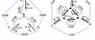
Star and triangle
The three-phase stator winding of the electric motor is connected according to the circuit depending on the mains supply voltage. The ends of a three-phase winding can be: connected inside the electric motor (three wires come out of the motor), brought out (six wires come out), brought into a distribution box (six wires come out of the box, three wires come out of the box).
Phase voltage - potential difference between the beginning and end of one phase
Another definition for a star connection: phase voltage is the potential difference between the line wire and the neutral (note that the delta connection does not have a neutral)
Line voltage
- potential difference between two linear wires (between phases).
| Star | Triangle | Designation |
| Uл, Uф - linear and phase voltage, V, | ||
| Il, Iph - linear and phase current, A, | ||
| S — total power, W | ||
| P—active power, W |
Attention: Although the power for star and delta connections is calculated using the same formula, connecting the same electric motor in different ways to the same electrical network will result in different power consumption. In this case, incorrect connection of the electric motor can lead to melting of the stator windings.
Example: Let’s say the electric motor was connected in a star configuration to a three-phase alternating current network Ul=380 V (respectively Uph=220 V) and consumed current Il=1 A
Total power consumption:
S = 1.73∙380∙1 = 658 W.
Now let’s change the connection diagram to a “triangle”, the linear voltage will remain the same Uл=380 V, and the phase voltage will increase by the root of 3 times Uф=Uл=380 V. An increase in the phase voltage will lead to an increase in the phase current by the root of 3 times. Thus, the linear current of the delta circuit will be three times greater than the linear current of the star circuit. And therefore the power consumption will be 3 times greater:
S = 1.73∙380∙3 = 1975 W.
Thus, if the motor is designed to be connected to a three-phase AC network in a star configuration, connecting this electric motor in a delta configuration may lead to its failure.
If in normal mode the electric motor is connected in a delta circuit, then to reduce the starting currents during the start-up it can be connected in a star circuit. In this case, along with the starting current, the starting torque will also decrease.
Connecting an electric motor according to a star and delta circuit
Designation of the stator terminals of a three-phase electric motor
Designation of the terminals of the stator windings of newly developed
three-phase machines according to
GOST 26772-85
| Winding connection diagram, name of phase and output | Pin designation | |
| Start | End | |
| Open circuit (number of pins 6) | ||
| first phase | U1 | U2 |
| second phase | V1 | V2 |
| third phase | W1 | W2 |
| Star connection (number of pins 3 or 4) | ||
| first phase | U | |
| second phase | V | |
| third phase | W | |
| star point (zero point) | N | |
| Delta connection (number of pins 3) | ||
| first conclusion | U | |
| second conclusion | V | |
| third conclusion | W |
previously developed stator winding terminals
and modernized three-phase machines in accordance with
GOST 26772-85
| Winding connection diagram, name of phase and output | Pin designation | |
| Start | End | |
| Open circuit (number of pins 6) | ||
| first phase | C1 | C4 |
| second phase | C2 | C5 |
| third phase | C3 | C6 |
| Star connection (number of pins 3 or 4) | ||
| first phase | C1 | |
| second phase | C2 | |
| third phase | C3 | |
| zero point | ||
| Delta connection (number of pins 3) | ||
| first conclusion | C1 | |
| second conclusion | C2 | |
| third conclusion | C3 |
Checking for open circuit
How to check the generator stator for a break? To begin with, you should switch the measuring device to ohmmeter mode, after which we bring the probes to the winding terminals. If there is no break, the multimeter will show values below 10 ohms. Otherwise, the readings will tend to infinity. Thus, no current passes through the winding, which indicates the presence of a break. So you need to check all the conclusions.
If using a light bulb, we check in the following sequence. First, we connect the negative terminal of the battery with one of the winding terminals with a wire (preferably insulated). We supply the plus batteries to the other terminal through the lamp. Its light will indicate complete order, but if the lamp does not light up, it means there will be a break. This must be done with every conclusion.
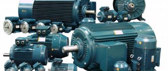
Motors used in industry
Both types of motors are successfully used in industry: asynchronous with a squirrel-cage rotor, and synchronous commutator.
The first type of device has important advantages:
- Low price;
- Reliability and durability;
- Easy to use.
There are also disadvantages:
- Impossibility of smooth control of armature speed;
- Low rotation speed - limit 3000 rpm. in networks with a frequency of 50Hz;
- Large starting currents.
However, the advantages of these products far outweigh their disadvantages.
For your information. Asynchronous motors are used in those devices that require constant operating modes of industrial or transport equipment. For example, in drives of various pumps, belt conveyors, in ventilation systems, in lifting mechanisms. The niche of asynchronous electric machines occupies 65-75% of the total volume of electric motors used.
Synchronous commutator motors have their advantages:
- Possibility of smooth, stepless change of rotation speed;
- Great power;
- High rotation speed.
Disadvantages inherent in commutator electric motors:
- Relatively high cost;
- Sliding contacts of the armature commutator, reducing operational reliability and reducing the service life of the machine;
- Frequent maintenance required.
They are used where a smooth change in angular speeds is necessary: these are machine tool drives, traction motors of electric vehicles, and precision installation systems.
Both types of engines are widely used in industry and everyday life. For their long-term and trouble-free operation, it is necessary to carry out routine maintenance, and, if necessary, restoration repairs, including rewinding the stator and rotor windings.
Car electrical equipment
All electrical equipment of any car is represented by the following components:
- Current sources:
- accumulator battery;
- generator.
- basic;
- long-term;
- short-term.
The task of the battery is to provide consumers with current while the engine is “resting”, during its startup or operation at low speeds. While the generator is, in fact, the main supplier of electricity. It not only powers all consumers, but also charges the battery.
Its capacity, combined with the power of the generator, must meet the needs of all consumers, regardless of the engine operating mode. In other words, energy balance must be constantly maintained. This is important to know, as it will allow you to understand how the generator stator works.
The main consumers usually include the fuel system, including injection, ignition, control, and automatic transmission. Some cars have electric power steering. That is, everything that constantly uses current, from starting the engine to stopping it completely.
Long-term consumers are systems that are not used very often. And this is lighting, security (passive, active), heating and air conditioning devices. Most cars are equipped with anti-theft systems, multimedia equipment and navigation.
As for short-term consumers, these are the cigarette lighter, starting system, glow plugs, signal, as well as comfort systems.