Hello, dear readers! Today we will learn what the time-current characteristic (TCC) is; let’s look at the CTC using the example of fuses and switches. So…
Electric current has one distinctive feature: it can only flow in a closed circuit. If this chain is broken, then its effect immediately ceases. This property is embodied in the operation of maximum current protection based on the use of fuses and circuit breakers.
They are selected in such a way that they can withstand the rated current flowing through them for a long time. This ensures the reliability of power supply to consumers. At the same time, fuses and circuit breakers have protective functions: during emergency conditions in a controlled circuit, they break the dangerous current passing through them.
In this case, two factors are taken into account:
- magnitude of the flowing load current
- duration of its effect
The fuse link burns out from the thermal effect created by the current passing through it.
The circuit breaker also takes into account the thermal overheating of the circuit and opens its power contacts due to the operation of the thermal release. At the same time, it contains another device - an electromagnetic release, which reacts to excess electromagnetic energy that occurs even in pulse mode.
More details about the device, principle of operation and operating features of circuit breakers and fuses are described here:
Circuit breaker. Internal structure, characteristics.
Types of fuses. Type, device and design.
The operation of all these devices is judged by certain technical characteristics, which are usually called time-current because they accurately determine the response time of the protection, taking into account its dependence on the excess current ratio of the emergency mode relative to the nominal state.
The time current characteristic (TCC) is expressed by graphs in Cartesian coordinates. The ordinate axis is time, counted in seconds, and the abscissa is the ratio of the flowing current in emergency mode I to the nominal value In of the switching device.
Why is a protective characteristic created for a fuse link?
In order to ensure proper operation of the fuse inside the electrical circuit, it is necessary to take into account:
- technical capabilities
- inspection conditions
- appointment
Main parameters of the protective characteristics of the fuse
The graph of fuses tripping at different currents is expressed by a curved line dividing the working coordinate space into two parts:
- working area in which the fuse-link remains intact and reliably ensures the flow of current through the protected circuit
- zone of flow of limit currents, in which the electrical circuit breaks
The first part of the graph is shown in light green, and the second is highlighted in beige.
Protective characteristic of fuse link
The protective characteristic of a fuse link lies on the border of these two zones. In the space of operating currents, the fuse remains intact, and when their values increase above the critical state, it blows out.
The limit current zone is dangerous for equipment and must be turned off as quickly as possible.
The protective characteristic of a fuse link expresses the duration of the period of time from the beginning of the creation of an emergency mode until the moment of its shutdown, presented depending on the excess of the dangerous current over the rated value of the fuse.
The fuse-link is characterized by three types of currents:
- nominal, which it can withstand for an almost unlimited time
- minimum test, under which one can work for more than one hour
- maximum test, which causes it to burn out in less than one hour
The fuse link protects the circuit connected to it from two types of emergency modes:
- overloads with increased loads that turn off with a delay
- short circuits - short circuits requiring the fastest possible elimination
All these modes and types of currents are taken into account when choosing a fuse and fuse link. For this purpose, mathematical relationships have been developed, transformed into graphs and tables in a convenient form.
How is the protective characteristic of a fuse created?
The fuse link can operate as a protection only once. After that it burns out. Therefore, its characterization can only be created indirectly.
To do this, the factory randomly selects a certain number of samples from each batch of finished products. They are used to carry out further electrical tests under the influence of various currents. Based on their results, tables and graphs are compiled that allow one to judge the quality of the released series of fuses.
Purpose of the protective characteristics of the fuse
The fuse link is evaluated by electrical parameters to solve a purely practical problem: ensuring its correct selection in terms of operating and protective properties.
To do this, take into account:
- the value of the operating voltage of the circuit in which the fuse must operate
- limit switchable current at a fuse link that can break it (turn it off)
- the value of the rated current of the fuse, taking into account its load factors and overload detuning.
Without using the protective characteristics of the fuse link, it is impossible to select the correct fuse for its reliable operation in the electrical circuit.
Classification of devices
A fuse is a single-pole switching device designed to protect electrical circuits from overcurrents; its action is based on the melting of a metal insert of a small cross-section by current and extinguishing the resulting arc. Valuable properties of fuses are:
- simplicity of the device and, therefore, low cost;
- exceptionally fast circuit disconnection during short circuit;
- the ability of some types of fuses to limit short-circuit current.
- However, it should be pointed out that:
- the characteristics of the fuses are such that they cannot be used to protect circuits under overloads;
- selective shutdown of circuit sections when protected by fuses can be ensured only in radial networks;
- automatic restart of the circuit after it has been turned off by a fuse is only possible when using multiple-action fuses of a more complex design;
- disconnection of circuits by fuses is usually associated with overvoltages;
- single-pole outages and subsequent abnormal operation of sections of the system are possible.
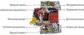
Therefore, in electrical installations above 1 kV, fuses have limited use; They are mainly used to protect power transformers, voltage instrument transformers and static capacitors. A fuse consists of the following main parts: an insulating base or a metal base with insulators, a contact system with clamps for connecting conductors, a cartridge with a fuse link. Most fuses have trip indicators of one design or another.
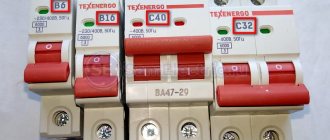
Fuses of various ratings.
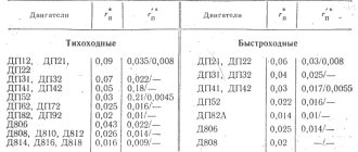
Fuses are characterized by rated voltage, rated current and rated breaking current. It is necessary to distinguish between the rated current of the fuse link and the rated current of the fuse (contact system and cartridge). The latter is equal to the rated current of the largest of the inserts intended for it. For AC fuses with a rated voltage from 3 to 220 kV inclusive, the following rated current values are established:
- Rated currents of fuses, A……8; 10; 20; 32; 40; 50; 80; 160; 200; 320; 400
- Rated currents of fuse links, A……2; 3.2; 5; 8; 10; 16; 20; 32; 40; 50; 80; 160; 200; 320; 400
- Rated shutdown currents, kA……2.5; 3.2; 4; 5; 6.3; 8; 10; 12.5; 16; 20; 25; 31.5; 40
The rated breaking current should be understood as the maximum permissible effective value of the periodic component of the short-circuit current, turned off by a fuse under certain conditions. Domestic hardware factories produce fuses for voltages up to 110 kV inclusive. The highest temperature of the fuse parts charged with any of the fuse-links intended for it should not exceed the values indicated in Table 1 at an air temperature of +40°C.
How does the time-current characteristic of a circuit breaker work?
The choice of current characteristic time is influenced by:
- design features of built-in protections
- configuration of the selected chart
Influence of the circuit breaker protection design on the shape of its response characteristics
The protective properties of the circuit breaker are ensured by two built-in devices operating on the principles of direct-acting relays. They release the power contacts of the machine when the rated values are exceeded according to the limitation criteria:
- thermal load
- electromagnetic influence
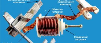
The bimetallic plate of the thermal release perceives the heating of the winding wires. When it is exceeded, it bends, removing the clutch assembly from being held.
Operating principle of thermal release
Under the action of the tension force of the spring, the movable rocker arm, released from its hold, rotates, and its power contacts break the power circuit.
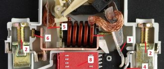
With an electromagnetic release, the power contacts are disconnected due to the knocking out of the spring holding lever by the blow of the pusher, which occurs under the influence of the emergency current.
Operating principle of an electromagnetic release
Unlike a blow-out fuse, both of these devices are designed to be reusable. They allow you to quickly restore circuit shutdowns after preventing abnormal situations.
The operation of the thermal release and electromagnetic cut-off is included in the circuit breaker shutdown algorithm and is comprehensively taken into account when it is triggered during the current characteristic.
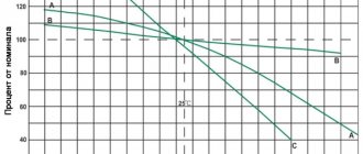
Since the temperature of the environment and the bimetallic plate affect the speed of operation of the protections, all measurements are usually carried out at +30 degrees Celsius.
The time graph of the current characteristic for a circuit breaker is a complex line marked with the letters ABC. The upper section AB corresponds to the operation of the thermal release, and its lower part BC corresponds to the electromagnetic cutoff.
Time current characteristic of circuit breaker
Execution options
Low current inserts
Fuse for low power electrical appliances
Used to protect low-power circuits, typically up to 20 amperes. It is a glass (ceramic) cylinder with metal bases connected to each other inside by a thin wire. When overloaded or short-circuited, the wire burns, breaking the circuit and preventing subsequent destruction by excessive temperature. They vary in size:
- 3x15
- 4x15
- 5×20
- 6×32
- 7x15
- 10x38
Fork fuses
plug fuses
Fork fuses are most widely used in DC electrical circuits of vehicles; they are produced for operating voltages up to 30 volts. The design of such fuses is shifted to one side: electrical contacts on one side and a fusible (protective) part on the opposite.
- By design, fork fuses are divided into: miniature fork
- regular fork
Cork
Neozed plug fuses
The most common type of fuses in old electrical installations of residential buildings in the countries of the former USSR. The design consists of a porcelain body, inside of which there is a thin wire (which burns in emergency mode); To ensure that the two ends of the wire are separated from each other during combustion, a weight painted in a certain color hangs on one end of the wire (each color corresponds to a certain current strength). As a rule, the condition of the fuse is determined by the position of the load: if it hangs on a piece of wire, then the fuse has burned out and requires replacement.
- By type of construction they differ into: DIAZED
- NEOZED
Coloring according to rated current
| Current strength | Receipt color | Maximum power (220 V network) |
| 2 A | Pink | 460 Watt |
| 4 A | Brown | 900 Watt |
| 6 A | Green | 1,200 Watt |
| 10 A | Red | 2,000 Watt |
| 16 A | Grey | 3,200 Watt |
| 20 A | Blue | 4,000 Watt |
| 25 A | Yellow | 5,200 Watt |
| 32-50 A | Black | 7,300 -11,500 Watts |
| 60 - 63 A | Dark red | 13,800 -14,500 Watts |
Knife
internal structure of the blade fuse
The most common type of fuses in industrial electrical installations, they are available for high currents, up to 1250 amperes. They are a source of increased danger, since the use involved installation in a holder with non-insulated jaws; For this reason, they try to use blade fuses only in places where the maintenance of the electrical installation is provided exclusively by qualified personnel who have both the necessary equipment and the appropriate safety skills. In the modern assortment you can find blade fuse disconnectors in a dielectric housing, which reduce the risk of injury during maintenance and/or replacement.
- Differences in blade fuses by design type: 000 (up to 100 amperes)
- 00 (up to 160 amps)
- 0 (up to 250 amps)
- 1 (up to 355 amps)
- 2 (up to 500 amperes)
- 3 (up to 800 amperes)
- 4a (up to 1250 amperes)
Time current characteristic, main parameters of the graph
Taking into account the influence of temperature
In contrast to the protective characteristics of the fuse link of a circuit breaker, the VTX graph is represented by two lines:
- upper, taking into account the activation of protection directly from a cold state of +30О С
- lower, created after restarting, when the machine’s structure did not have time to cool down
The area between these two extreme graphs is highlighted in color. When operating a circuit breaker, be aware that it may be located somewhere within the area shown. In this case, the shutdown time of emergency currents is slightly reduced in a warm state and increases in a cold state. Due to this, a spread of response parameters is created.
The temperature of structural components can have a significant impact on the response time of the machine. This becomes especially relevant when conducting electrical tests that require multiple measurements. To repeat them, it is necessary to provide time for the protection to cool down to +30 degrees.
Division of VTX into zones
Circuit breakers strictly divide the current characteristic time into zones to highlight operational areas:
- inside the first one must ensure reliable flow of operating currents
- and in the second - emergency modes are switched off
Conditional non-trip current line
In order to indicate the first area on the abscissa axis of the graph, the value 1.13 I/I nom was selected. It is called the conditional non-disconnection point. Below these currents, tripping of the circuit breaker should not occur.
When it is reached, circuit breakers with a rated current of up to 63 amperes must turn off after 1 hour, and with higher ratings - after two.
Time current characteristic of circuit breaker
The location of the conditional release point is necessarily indicated on the VTX chart.
Conditional trip current line
The point on the abscissa axis with a value of 1.45 I/I nom is the second limit value of the zone of conditional tripping and non-tipping currents of power contacts.
Time current characteristic of circuit breaker
The point 1.45 I/I nom characterizes the conditional tripping currents; it is also indicated on all VTX graphs. When the load connected to the machine reaches such a value, it must turn off within the time:
- less than 1 hour if rated up to 63 amperes
- no longer than two hours when the rated current exceeds this value of 63 amperes
The above graph shows that for the selected circuit breaker, the emergency shutdown time from a cold state is 1 hour, and when it warms up, it can decrease to 40 seconds.
AC fuses in DC circuits
With that in mind, let's look at an example of testing the suitability of a particular fuse in a DC circuit. The information below applies specifically to the 660, 690, 1000 and 1250 VAC standard series rectangular fuses. However, in the catalog there is no information for them about the possibility of their use in DC circuits. However, these fuses can be used in circuits where DC voltage is used. However, it is necessary to carry out a certain verification calculation.
The breaking capacity of the fuses depends on the combination of:
- maximum applied constant voltage;
- time constant of the L/R circuit;
- minimum expected short circuit current Ipmin of the circuit;
- pre-arc integral I2t of the selected fuse.
Calculation example.
Background information:
We use the parameters of a specific fuse 170M6149: 1100A, 1250 VAC,
I2t - 575.000 A2s
Applied voltage E = 500V DC
Possible short circuit current Ip = E/R = 500/16 = 31.3 kA
Time constant L/R = 40 ms (0.64/16)
Fig.4. Conditional diagram of the calculated circuit
A number of the following dependencies are used for calculations:
Step. 1 The graph in Fig. 5 shows the dependence of the maximum applied DC voltage on L/R with 3 levels of current Ip as a parameter.
It is necessary to select curve 1, 2 or 3 above the intersection point of the known voltage and time constant. We find the intersection point for an applied voltage of 500 V and a time constant of 40ms. Directly above this intersection point is curve 2.
If there is no curve above the intersection of the voltage and time constant, then a fuse with an AC voltage rating greater than 1250 V must be selected.
Fig.5. Dependence of the maximum applied DC voltage on L/R
Step 2. To correctly use the fuse, it is necessary to use the factor F, which relates I2t to the expected tripping current Ipmin. Figure 6 shows the dependence of the coefficient F on L/R. Using parameter 2 (selected curve 2) for the time constant L/R = 40 ms, we find the coefficient F = 26.5.
Fig.6. Determination of the intermediate coefficient F depending on the time constant
Step 3. For an applied voltage of 500V, at the intersection with the rated voltage curve of the fuse used, we find the peak arc voltage when the fuse trips.
As can be seen from the graph (Fig. 7), for this case, the peak arc voltage when the fuse trips will reach a value of 1900V.
Fig.7. Determination of peak arc voltage when a fuse trips
Step 4. The minimum current level (Ipmin) of the circuit must meet the following condition:
Testing with specific circuit parameters has shown that the breaking capacity of the selected fuse is sufficient under the following basic conditions:
- The maximum applied voltage is 500V;
- Time constant 40ms (allowable up to 46ms);
- The minimum required operating current Ip is 20kA (for this circuit we have 31.3kA, which fully corresponds to the condition);
- Peak arc voltage when the fuse trips is 1900 V.
Once again, the above applicability testing technique applies specifically to standard series rectangular fuses of 660, 690, 1000 and 1250 VAC. The possibility of using other high-speed fuses in DC circuits must be clarified in the reference data of the relevant catalogs.
Thus, fuses allow operation in both alternating and direct current circuits, but with a significant correction of the maximum permissible parameters, in particular voltage. However, there is no universal correct method for selecting a fuse for direct current, based on its parameters for alternating current. In this regard, the manufacturer recommends using fuses specially designed for this purpose in DC circuits or fuses whose reference data stipulates the possibility of operating in DC mode.
Practical application of VTX parameters
Analysis of the use of the time-current characteristics of circuit breakers based on the conditional tripping currents of power contacts makes it possible to take into account the duration of overloads in the connected electrical circuit. This is important to do because they can damage the equipment.
For example, when choosing a machine with a rating of 16 amperes and keeping it in a cold state, a conditional trip current of 1.45∙16 = 23.2 amperes will act on the connected electrical wiring for one hour. This time is quite enough to overheat the insulation of copper wires with a cross-section of 1.5 mm square and disable it, creating conditions for a fire. And cases of protection of such conductors, and even 2.5 mm sq. aluminum conductors, by such automatic devices are still often encountered in practice.
To eliminate such situations, it is recommended to carefully analyze the time-current characteristics of circuit breakers in relation to the load connected to them. To facilitate their selection, a table of correspondence between rated currents and cross-sectional areas of copper conductors of cables and wires has been created.
Table for selecting circuit breakers by rated current and cross-section of cable line cores
Manufacturers of circuit breakers test all their products for compliance with accepted standards. The basic requirements for automatic machines are set out in GOST R 50345-2010. However, in some areas, the current characteristics of each plant may differ slightly. This feature must be taken into account when choosing a specific model and testing it.
Markings and symbols
Each manufacturer produces fuses under a specific code or article number. The fuse number allows you to find and clarify technical specifications in catalogs. Often these codes can be found on product bodies. The code can also be applied to the metal part. In addition to codes, basic data can also be indicated on the case - this is the rated current in A, rated voltage in V, disconnecting characteristics or design features. Using this data, you can determine the purpose of the fuses.
So, the rated current is the maximum permissible value at which the part can function normally for a long time.
Rated voltage is the maximum permissible voltage at which the part safely breaks the circuit in the event of a short circuit or overload in the network.
Breaking capacity is called maximum currents. With them, the fuse will work, but its housing will not be destroyed.
Characteristics are the dependence of the time at which the fusible element collapses on the current that flows through the part. Different types of fuses according to their characteristics are grouped into groups according to their application features and response speed.
The second letter denotes the types of chain:
- G – general purpose circuit.
- L – protection of cables and distribution systems.
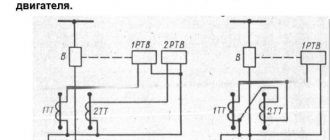
- M – protection of circuits in electric motors.
- Tr is a fuse capable of protecting a transformer network.
Items with the letter R are used in conjunction with power semiconductor equipment. And PV will be able to provide protection for solar panels.
So, we looked at what types of fuses there are and what markings they have.
Types of time-current characteristics of circuit breakers
Automatic protection can be created for different purposes depending on operating conditions. According to these indicators, their performance characteristics graphs have different response time limits. This allows them to be tuned according to selectivity and avoid false equipment shutdowns. Circuit breakers are produced for domestic or industrial use.
Electric current has one distinctive feature: it can only flow in a closed circuit. If this chain is broken, then its effect immediately ceases. This property is embodied in the operation of maximum current protection based on the use of fuses and circuit breakers.
They are selected in such a way that they can withstand the rated current flowing through them for a long time. This ensures the reliability of power supply to consumers. At the same time, fuses and circuit breakers have protective functions: during emergency conditions in a controlled circuit, they break the dangerous current passing through them.
In this case, two factors are taken into account:
1. the magnitude of the flowing load current;
2. duration of its influence.
The fuse link burns out from the thermal effect created by the current passing through it.
Fuses are single-pole devices designed to automatically switch off an electrical circuit in the event of a short circuit or overload. Automatic shutdown is carried out by melting the metal fuse insert with the current of the protected circuit and extinguishing the resulting electric arc.
The circuit breaker also takes into account the thermal overheating of the circuit and opens its power contacts due to the operation of the thermal release. At the same time, it contains another device - an electromagnetic release, which reacts to excess electromagnetic energy that occurs even in pulse mode.
A circuit breaker is a contact switching device capable of switching on, conducting and disconnecting currents in the normal state of an electrical circuit, as well as switching on, conducting for a certain set time and switching off currents in a certain abnormal state of the electrical current circuit (during short circuits or overloads).
In the modern world, circuit breakers are used everywhere in residential buildings and in production as the main protection of equipment against overload and short-circuit currents.
The operation of all these devices is judged by certain technical characteristics, which are usually called time-current (protective) because they accurately determine the response time of the protection, taking into account its dependence on the excess current ratio of the emergency mode relative to the nominal state.
Time-current characteristics (TCC) are expressed by graphs in Cartesian coordinates. The ordinate axis is time, counted in seconds, and the abscissa is the ratio of the flowing current in emergency mode I to the nominal value In of the switching device.
Why is a protective characteristic created for a fuse link?
In order to ensure proper operation of the fuse inside the electrical circuit, it is necessary to take into account:
- technical capabilities;
- inspection conditions;
- appointment.
Main parameters of the protective characteristics of the fuse
The graph of fuses tripping at different currents is expressed by a curved line dividing the working coordinate space into two parts:
1. working area in which the fuse-link remains intact and reliably ensures the flow of current through the protected circuit;
2. the zone of flow of limit currents, in which the electrical circuit breaks.
The first part of the graph is shown in light green, and the second is highlighted in beige.
The protective characteristic of a fuse link lies on the border of these two zones. In the space of operating currents, the fuse remains intact, and when their values increase above the critical state, it blows out.
The limit current zone is dangerous for equipment and must be turned off as quickly as possible.
The protective characteristic of a fuse link expresses the duration of the period of time from the beginning of the creation of an emergency mode until the moment of its shutdown, presented depending on the excess of the dangerous current over the rated value of the fuse.
The fuse-link is characterized by three types of currents:
1. nominal, which it can withstand for an almost unlimited time;
2. a minimum test, under which one can work for more than one hour;
3. maximum test, which causes it to burn out in less than one hour.
The fuse link protects the circuit connected to it from two types of emergency modes:
1. overloads with increased loads that turn off with a delay;
2. short circuits - short circuits that require the fastest possible elimination.
All these modes and types of currents are taken into account when choosing a fuse and fuse link. For this purpose, mathematical relationships have been developed, transformed into graphs and tables in a convenient form.
How is the protective characteristic of a fuse created?
The fuse link can operate as a protection only once. After that it burns out. Therefore, its characterization can only be created indirectly.
To do this, the factory randomly selects a certain number of samples from each batch of finished products. They are used to carry out further electrical tests under the influence of various currents. Based on their results, tables and graphs are compiled that allow one to judge the quality of the released series of fuses.
Purpose of the protective characteristics of the fuse
The fuse link is evaluated by electrical parameters to solve a purely practical problem: ensuring its correct selection in terms of operating and protective properties.
To do this, take into account:
- the value of the operating voltage of the circuit in which the fuse must operate;
- maximum switchable current at a fuse-link, capable of breaking it (disconnecting it);
- the value of the rated current of the fuse, taking into account its load factors and overload detuning.
Without using the protective characteristics of the fuse link, it is impossible to select the correct fuse for its reliable operation in the electrical circuit.
How does the time-current characteristic of a circuit breaker work?
The choice of time-current characteristic is influenced by:
- design features of built-in protections;
- configuration of the selected chart.
Influence of the circuit breaker protection design on the shape of its response characteristics
The protective properties of the circuit breaker are ensured by two built-in devices operating on the principles of direct-acting relays. They release the power contacts of the machine when the rated values are exceeded according to the limitation criteria:
1. thermal load;
2. electromagnetic influence.
The bimetallic plate of the thermal release perceives the heating of the winding wires. When it is exceeded, it bends, removing the clutch assembly from being held.
Under the action of the tension force of the spring, the movable rocker arm, released from its hold, rotates, and its power contacts break the power circuit.
With an electromagnetic release, the power contacts are disconnected due to the knocking out of the spring holding lever by the blow of the pusher, which occurs under the influence of the emergency current.
Unlike a blow-out fuse, both of these devices are designed to be reusable. They allow you to quickly restore circuit shutdowns after preventing abnormal situations.
The operation of the thermal release and electromagnetic cut-off is included in the circuit breaker shutdown algorithm and is comprehensively taken into account when it is triggered during the time-current characteristic.
Since the temperature of the environment and the bimetallic plate affect the speed of operation of the protections, all measurements are usually carried out at +30 degrees Celsius.
The time-current characteristic graph for a circuit breaker is a complex line marked with the letters ABC. The upper section AB corresponds to the operation of the thermal release, and its lower part BC corresponds to the electromagnetic cutoff.
Basic parameters of the time-current characteristic graph
Taking into account the influence of temperature
In contrast to the protective characteristics of the fuse link of a circuit breaker, the VTX graph is represented by two lines:
1. upper, taking into account the activation of protection directly from a cold state of +30°C;
2. lower, created after restarting, when the design of the machine did not have time to cool down.
The area between these two extreme graphs is highlighted in color. When operating a circuit breaker, be aware that it may be located somewhere within the area shown. In this case, the shutdown time of emergency currents is slightly reduced in a warm state and increases in a cold state. Due to this, a spread of response parameters is created.
The temperature of structural components can have a significant impact on the response time of the machine. This becomes especially relevant when conducting electrical tests that require multiple measurements. To repeat them, it is necessary to provide time for the protection to cool down to +30 degrees.
Division of VTX into zones
Automatic switches strictly divide time into zones
current characteristics to highlight operational areas: inside the first one, reliable flow of operating currents should be ensured, and in the second, emergency modes should be switched off.
Conditional non-trip current line
In order to indicate the first area on the abscissa axis of the graph, the value 1.13 I/I nom was selected. It is called the conditional non-disconnection point. Below these currents, tripping of the circuit breaker should not occur.
When it is reached, circuit breakers with a rated current of up to 63 amperes must turn off after 1 hour, and with higher ratings - after two.
The location of the conditional release point is necessarily indicated on the VTX chart.
Conditional trip current line
The point on the abscissa axis with a value of 1.45 I/I nom is the second limit value of the zone of conditional tripping and non-tipping currents of power contacts.
The point 1.45 I/I nom characterizes the conditional tripping currents; it is also indicated on all VTX graphs. When the load connected to the machine reaches such a value, it must turn off within the time:
- less than 1 hour if rated up to 63 amperes;
- no longer than two hours when the rated current exceeds this value of 63 amperes.
The above graph shows that for the selected circuit breaker, the emergency shutdown time from a cold state is 1 hour, and when it warms up, it can decrease to 40 seconds.
Automatic circuit breakers with combined releases have a relatively simple design and low cost. However, there are also disadvantages - dependence on the ambient temperature, high consumption of electrical energy, lack of adjustment of the time and current of protection operation, as well as insufficiently accurate and reliable operation.
Practical application of VTX parameters
Analysis of the use of the time-current characteristics of circuit breakers based on conditional tripping currents of power contacts makes it possible to take into account the duration of overloads in the connected electrical circuit. This is important to do because they can damage the equipment.
For example, when choosing a machine with a rating of 16 amperes and keeping it in a cold state, a conditional trip current of 1.45∙16 = 23.2 amperes will act on the connected electrical wiring for one hour. This time is quite enough to overheat the insulation of copper wires with a cross-section of 1.5 mm square and disable it, creating conditions for a fire. And cases of protection of such conductors, and even 2.5 mm sq. aluminum conductors, by such automatic devices are still often encountered in practice.
To eliminate such situations, it is recommended to carefully analyze the time-current characteristics of circuit breakers in relation to the load connected to them. To facilitate their selection, a table of correspondence between rated currents and cross-sectional areas of copper conductors of cables and wires has been created.
Manufacturers of circuit breakers test all their products for compliance with accepted standards. The basic requirements for automatic machines are set out in GOST R 50345-2010. However, in some areas, the time-current characteristics of each plant may differ slightly. This feature must be taken into account when choosing a specific model and testing it.
Types of time-current characteristics of circuit breakers
Automatic protection can be created for different purposes depending on operating conditions. According to these indicators, their performance characteristics graphs have different response time limits. This allows them to be tuned according to selectivity and avoid false equipment shutdowns.
Circuit breakers are produced for domestic or industrial use.
Household machines are classified into three groups B, C and D:
1. Class B is designed to protect long lines and lighting systems. The multiplicity of currents for its operation lies within 3÷5 In;
2. Class C protects socket groups or equipment that creates moderate inrush currents. Current multiplicity 5÷10 In;
3. Class D is used to protect consumers with high starting currents, for example, transformers or machine tools with powerful asynchronous electric motors. Current multiplicity 10÷20 Inom.
Type B circuit breakers are more sensitive. They are used to protect end consumers inside apartments and houses. And as an introductory machine, it is better to install those that belong to type C.
The quality of the electrical wiring and the resistance value of the phase-zero loop can influence the choice of circuit breaker. Old insulation with a high content of leakage currents and overestimated loop performance can worsen the operating conditions of a type C machine or lead to its failure. In such situations, class B is used.
Industrial machines are classified into three groups:
1. class L - more than 8 IN;
2. class Z - more than 4 Inom;
3. class K - more than 12 Inom.
Among manufacturers in European countries, there are models of automatic machines with class A, which has a current multiplicity limit of 2 ÷ 3 In.
All these features must be taken into account when choosing a circuit breaker design and testing it. Automatic machines designated with the same rating, depending on the type of time-current characteristic, have different response times.
Previously, ElectroVesti wrote that existing electronic devices on the market consist of inorganic, inanimate materials. However, laboratories are preparing “cyborg microbes” that will soon begin to produce electricity.
Based on materials from: electrik.info.