Isolation transformers are those with the same voltage or current characteristics at the output and output. Such devices have the same number of turns on the primary and secondary coils. As a result, the transformation coefficient is equal to unity. The use of such units increases safety, since there are no electrical connections in the secondary circuits with a voltage source or ground.
The separation of the input and output windings is ensured by reinforced double insulation. An additional measure is to place the coils on physically different cores.
The secondary winding is made without grounding the zero contact, so accidental touching it will not cause an electric shock unless a person simultaneously touches a metal pipe, does not stand in a damp place, or the danger of electric current passing through the body arises in another way.
How the device protects electrical appliances
Our homes are filled with household appliances and equipment that are connected to the power grid. Electrical appliances themselves are safe to use, which is ensured by manufacturers during their manufacture and is guaranteed by appropriate quality certificates.
However, a number of unfavorable factors affecting devices and network wiring in each individual room can worsen their insulation and create conditions for the passage of current through the human body, which will lead to electrical injury. These factors include:
- heat;
- humidity in the air and in the places where the wiring passes;
- the presence of metal products with unstable grounding;
- mechanical damage to the insulation.
Compact isolation transformer.
When an electric current leaks, voltage appears on the metal surfaces of not only the devices themselves, but also on pipelines or other metal objects surrounding the user.
The highest risk of electric shock is in the bathroom. Because it contains all the negative factors affecting insulation.
Electric shock can be avoided by using protective measures. This is a reliable grounding of the housings of electrical appliances, so that in the event of accidental insulation breakdowns, dangerous currents pass through the grounding circuits.
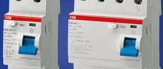
They are also protected by the use of RCDs or differential circuit breakers in the input load connection circuits, which disconnect the network in the event of ground leaks.
Such protection measures are based on the fact that the ground for all electricity consumers is part of the electrical circuit. Protective electrical grounding simply bridges the circuit that may arise between a phase accidentally falling on the electrical equipment body and the ground through the human body in case of accidental contact.
Interesting read: how to assemble a Tesla coil yourself.
Another method of protection would be to exclude the connection of the earth with the electrical network and this can be achieved through complete galvanic isolation of the primary and secondary electrical networks. This is achieved by using safe isolation transformers, the devices of which will be discussed below.
The specific nature of some household appliances, such as a washing machine or hair dryer, requires them to be constantly connected to the power grid in conditions of high humidity, which increases the risk of electric shock from a faulty appliance or broken wiring.
Accidental touches to the conductive phases and the neutral wire will lead to tragic consequences. The 220 V voltage from the power supply network is formed according to the connection scheme of all three circuits with a potential difference of 380 V between them with a neutral wire, which is connected (grounded, as they say in everyday life) to a potential in the ground.
Connection diagram of the isolation transformer and devices to it.
This scheme predetermines the presence of phase voltage between each of the three network linear wires (colloquially referred to as phases) and zero (neutral) - ground. If the conductor insulation is broken, the phase voltage passes to the housing of the household appliance.
Simultaneous contact by the user of such a “broken” case and grounded metal objects such as heating radiators, faucets or water taps provokes the passage of electric current through the human body with all traumatic consequences.
AVR 2 Series
Devices in this series have become the smartest among all Torus systems. The AVR2 series includes the functionality of AVR models with advanced Ethernet control and monitoring functions, high performance and security. Here, as in other Torus Power products, NBT filtering works, there is SMSS surge suppression, and AVR voltage regulation.
Network air conditioner Torus Power AVR2 30 CE with information display on the front panel
By advanced control functions, the manufacturer means the ability to assign separate groups of sockets, set a device operation schedule, turn-on delay, etc.
Network air conditioner Torus Power AVR2 8 CE
The AVR and AVR2 series are ideal for use in the installation business.
Transformer no-load current. idle experience
Operating principle of the device
The operation of a low voltage isolation step-down transformer is based on the galvanic isolation effect. Technically, this is implemented in the form of autonomous operation of both coils. The coils of the device are physically separated, that is, they do not touch each other.
This ensures safe operation provided that the circuits are not short-circuited due to mechanical stress. To completely eliminate the possibility of contact, the windings are insulated with several layers of high-quality insulation.
Isolation transformer circuit.
Passing through the primary winding, the current induces electricity in the secondary coil, to which circuits with consuming equipment are connected. The secondary winding of the RT or devices connected to it cannot have contact with ground or neutral.
It will be interesting➡ Design and circuit of a three-phase transformer
Significant increase in operational safety even in the event of a breakdown in the housing. With this scheme, a breakdown will not cause a current overload in the circuit, and the device itself will remain fully functional.
If a person comes into contact with an electrical appliance under emergency voltage connected through an isolation transformer, there will be no fatal injury from leakage current. Since it will not exceed a life-threatening level.
One of the operational features of isolation voltage transformers is the conversion coefficient equal to unity for most used models. Thus, both the input and output voltage are equal to the same value - 220 or 380 V.
When making calculations, it is necessary to take into account the energy costs for the operation of the device, since the efficiency of most models is in the range of 70-85%.
Centripetal jet turboexpander
Turboexpanders are continuous blade machines in which the flow passes through fixed guide channels (nozzles), which convert part of the potential energy of the gas into kinetic energy, and a system of rotating blade channels of the rotor, where the flow energy is converted into mechanical work, resulting in gas cooling.
They are divided according to the direction of flow into centripetal, centrifugal and axial; according to the degree of gas expansion in the nozzles - into active and reactive; according to the number of expansion stages - single- and multi-stage. The most common is a reactive single-stage centripetal expander developed by P. L. Kapitsa. Turbine expanders are braked by an electric generator, hydraulic brake, supercharger, and pump.
Turboexpanders are used mainly in installations with a low-pressure refrigeration cycle of 0.4-0.8 MN/ m2
(4-8
kgf/cm2 )
for volumetric (physical) gas flow rates of 40-4000
m3 / h
.
Turboexpanders have been created for low, medium and high pressure refrigeration cycles with volumetric gas flow rates of 1.5-40 m 3 /h
.
These machines are characterized by their small size (impeller diameter 10-40 mm
) and high rotor speed (100,000-500,000
rpm
).
Types of devices
At the moment, in electrical engineering, most transformers provide galvanic isolation of input and output circuits. Despite the fact that the “classical” definition of an isolation transformer implies the invariability of the value of the transformed parameter (voltage), in fact all types and types are isolation. Depending on the purpose, there are several types of transformers.
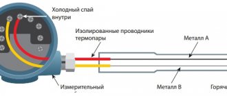
Current
Most often used to connect circuits on which measuring and recording devices (electricity meters, ammeters) and protective relays are installed.
Pulse
Converts the received signal into a rectangular pulse. Used to prevent high frequency interference.
Power
The design, most often, consists of several secondary windings that convert an incoming electrical impulse with one voltage system into several outgoing ones with other parameters of the voltage system.
Peak transformers
Used to convert the sinusoidal voltage component. The main purpose is to prevent interference in circuits with digitizing equipment.
Some sources list portable isolators as a separate category. It should be noted that the overall dimensions in the technical design of devices of various types do not play a key role.
Price of isolation transformers
The cost of these devices depends on the characteristics and purpose, as well as the pricing policy of the manufacturer and trade organization. On average, such equipment can cost from 9 to 70 thousand rubles, depending on the specified characteristics.
The table shows several examples of prices for these devices:
| Model | Load power, VA | Input voltage, V | Rated electric current value, A | Weight, kg | price, rub. |
| ORSZ-400 | 400 | 220 | 1,8 | 7 | 9600 |
| ORSZ-1000 | 1000 | 220 | 4,5 | 15 | 11500 |
| ORSZ-3000 | 3000 | 220 | 13,6 | 28 | 19900 |
| ORSZ-15000 | 15000 | 220 | 68 | 70 | 66000 |
The use of isolation transformers makes it possible to achieve a high level of safety in premises where special requirements are imposed on the operation of electrical networks. The user can select a device with the necessary characteristics, taking into account financial capabilities and parameters of the intended operation.
Source
Design features
Different types of isolation transformers can be either stationary or portable. Most often, portable devices have additional protection from external influences and are used in extreme operating conditions, in open areas.
Automatic transformers are not isolation transformers, since their design uses a different principle of arrangement of the primary and secondary windings.
They are combined into one, which forms, in addition to electromagnetic, a direct electrical connection. RTs for narrowly targeted use are being developed. For example, for hospitals and laboratories.
So-called medical isolation transformers are used to provide power supply with precisely defined parameters to sensitive devices installed in intensive care units, operating rooms of various biological, chemical and medical laboratories.
Material on the topic: interesting information about step-down transformers.
Classification
Currently, several types of isolation transformers are commercially produced, designed for the safe operation of electrical installations. The following types of such devices are distinguished:
The devices may provide for highly specialized conditions of use. Such devices are installed in medical institutions to supply power to operating rooms, inpatient departments and other important departments where high safety requirements are imposed.
Isolation transformer
Purpose of household transformer separators
Design of a medical isolation transformer.
A cardinal solution in terms of ensuring electrical safety in rooms such as bathrooms or basements is to prohibit the installation of sockets in them that connect directly to the power supply network.
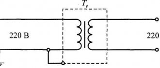
In this case, an isolation transformer (IT) is installed near the outlet, the task of which is not to convert the voltage up or down, but only to isolate the device using mains electricity from the network itself.
For the purpose of safe use of the same outlet in the bathroom, the RT is powered by its primary winding from a 220 V power network, and its secondary winding is connected to the outlet. In this way, galvanic isolation of the power supply system and the device of use is carried out. The principle of operation of the RT is illustrated by a schematic diagram of its connection and devices for use.
It is prohibited to ground the secondary winding of the RT and connected devices! Only the casing (housing) of the transformer is grounded.
Why apply additional protection?
The importance of using a device such as an isolation transformer can be demonstrated using a simple example. If a socket without galvanic isolation is installed in a bathroom, sauna or bathhouse, water entering it will lead to a short circuit. Insulation failure will occur. The voltage will have a destructive effect on the wall and ungrounded neighboring objects.
If there is a protective device in the electrical circuit, this effect of voltage can be minimized even if the insulation is destroyed. If the material is not pierced at all, there will be no effect of current on the objects surrounding the power point at all.
Therefore, in damp rooms, as well as when operating power tools, it is recommended to install protective settings. In some cases, manufacturers will not even provide a guarantee for the operation of the equipment if such units are not included in the network connection scheme.
Application of transformer separators
Design of an isolation transformer.
The design of the isolation transformer is made in complete analogy with the layout of the main functional elements in voltage converters of a step-up or step-down type of operation.
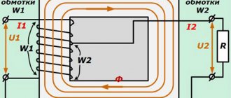
Also, primary and secondary windings with identical winding characteristics are installed on the magnetic circuit; according to the same laws of electromagnetic induction, alternating current electricity is converted from the primary winding to the secondary.
Since the voltage parameters of the output circuit repeat the same characteristics of the mains voltage applied to the primary, the voltage vectors in the circuits are practically the same.
The main design difference between RT and other transformers is the careful electrical insulation of the windings from each other. The connection between them is only magnetic due to the magnetic flux in the magnetic circuit.
It will be interesting➡ Transformers for LED strips, expert opinion
This method of transferring energy between circuits without direct electrical contact is called galvanic isolation. In this case, the secondary circuit of the transformer is not grounded! A sudden electrical breakdown will not cause an overcurrent; the leakage current in the event of accidental contact of a person with equipment under load will not exceed dangerous threshold values.
Connection to the boiler
To connect the isolation transformer to the boiler, you must turn off the power supply. During the installation process, it is necessary to decouple the galvanic circuit. For this you will need a 380/380V device. Equipment that protects the boiler from an emergency must have a maximum voltage threshold of at least 10-15%, compared to the boiler.
After this, you can start connecting devices. It is immediately necessary to disconnect the power along the phase line to connect to the neutral wire. For this purpose, a disconnecting device is used. The isolation transformer and boiler are tested during reheating. You should first wait until the system cools down completely.
Device characteristics
At its core, an isolation transformer resembles a step-down transformer of an ordinary electrical device, consisting of a primary and one (several) secondary windings. The turns of the primary windings of such transformers are separated by galvanic insulation from the secondary ones, however, in the event of emergency situations, for example, overheating, destruction of insulation or short circuit of the windings, the appearance of a phase in the secondary circuits could not be excluded. The main characteristics of isolation transformers are shown in the figure below.
Main technical characteristics of isolation transformers.
Isolating transformers have a transformation ratio equal to unity, provided by windings with identical parameters. And its main feature is the reliable galvanic separation of the windings.
This is realized by using reinforced or double insulation; the most reliable option is considered to be the decoupling of the primary and secondary windings by winding on different coils mounted on a single magnetic core. The efficiency of isolation transformers approaches 85%, but this is a worthy price to pay for electrical safety; it is not for nothing that such devices are called safety transformers.
The likelihood of suffering from secondary voltages in a network operating from an isolation transformer is minimized. Of course, the danger of electric shock remains if you touch both wires of the network (the concept of zero or phase in this circuit is not applicable), but each individually is neutral with respect to the ground and therefore does not pose a danger to human life.
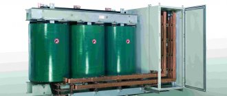
An industrial isolation transformer in a housing is a complete panel structure with a transformer (or several transformers), an input switch, circuit breakers, a network indicator, and a terminal block for connecting a cable.
The galvanic isolation created by the RT between the incoming power system and the consumer load circuit provides reliable protection for users at home and maintenance personnel in production. The model range includes as basic designs:
- single-phase isolation transformer;
- three-phase dry isolation transformer.
Which model to choose for installation in your apartment or in a separate building is already chosen by the homeowner in accordance with the recommendations of experts. Transformers are produced for various types of voltage. Among others, the most common typical combinations are:
- isolation transformer input 380/220V – output 380/220V
- isolation transformer input 380/220V – output 220/127V
- isolation transformer input 220V – output 220V
- isolation transformer input 220V – output 36V
- isolation transformer input 220V – output 24V
- isolation transformer input 220V – output 12V
Tables 1 and 2 show the main characteristics of three-phase isolation transformers 380/380V and 380/220V and single-phase isolation transformers 220-220V.
Table 1. Main characteristics of three-phase isolation transformers 380/380V and 380/220V.
Table 2. Characteristics of single-phase isolation transformers 220-220V.
Winding connection diagrams for three-phase transformers in input/output combinations:
- star
- triangle
- zigzag
During operation of the transformer, a situation may arise where the thermal switch is triggered when the temperature of the transformer exceeds 125 degrees C. In this case, the transformer is turned off. This situation can occur when the transformer is overloaded or the input network voltage is exceeded. With proper operation, the transformer resumes operation after approximately 20 minutes.
Overload capacity
Sometimes this is important. We calculated the transformer for a current density of 2.8 A/mmg to reduce the voltage drop across the winding and increase efficiency
However, the working current density value for it is 3.2 D/mm^2, which is what most transformers are designed for.
With such a current density in a wire with a diameter of 1.06 mm, the operating current will be 2.8 A. At a rated network voltage of 220 V, the transformer power will be 616 W, and at a network voltage of 230 V, respectively, 644 W. Taking the average value of 630 W . counting on uniform distribution of the load between the output voltages, we will keep in mind that our 500-watt transformer in an emergency will pull 130 watts more, but will heat up a little.
And connecting to it, fully loaded at 500 W, an oscilloscope and a soldering iron while setting up the equipment - no problem!
S. Komarov, UA3ALW. Moscow city. RM-06-17.
Literature:
- Komarov S. Transmitting complex of Individual radio broadcasting. - Radio, 2015. No. 9. pp. 21-26,
- TU 16.705.1 10-79. Round wires with enamel insulation based on polyesters.
- Transformers TA, TN, TAN, TPP for a frequency of 50 Hz according to 0100.471.001 TU.
- S. Komarov, UA3ALW. Correct calculation of the power transformer. - Radiomir, 2022. No. 3, pp. 34-36.
- GOST 24011-80. Magnetic cores are ring-shaped. Design and dimensions.
- GOST 23436-83, Cable paper, Technical conditions,
- GOST 28034-89, Electrical insulating lacquer fabrics. General technical requirements.
Advantages and scope
Isolating transformers are widely used in almost all areas of electrical engineering. They provide the user with a wide range of specific benefits depending on the industry in which they are used:
- devices with a transformation ratio of 1:1 are used in AC power networks without the need for additional grounding and insulation of peripheral equipment;
- isolation of DC circuits in communication lines. If it is necessary to use signal amplifiers, the use of RT makes it possible to separate the direct current for connecting the amplifier from the components of the information electrical pulse;
- increasing the safety of electrical equipment operation. Minimizes the risk of fatal electrical shock by isolating the user or operator from high-power sources;
- when testing, servicing or repairing equipment, it makes it possible to carry out work on devices that are turned on. In this case, isolation transformers are used with a ratio of 1:1, but having a low voltage power of the secondary circuit;
- filter out (cut off outside the operating range) the distorted sinusoidal voltage waveform, bringing it to the correct one. Reduce the negative impact of pulse width modulations;
- neutralizes a wide range of noise generated when connecting audio devices (amplifiers) to speakers.
It will be interesting➡ Necessary conditions for parallel operation of transformers
The use of isolation transformers is determined by the operational requirements and specific application of electrical networks:
- High humidity or the presence of water in the room, the presence of metal products without grounding or with weak grounding: bathrooms and shower rooms, power switching cabinets located on the street, cable wells, basements and semi-basements.
- Remote tracking, measurement and control posts in medical institutions, data and call centers, as well as other institutions where it is necessary to increase the level of personnel protection and the safety of equipment operation.
- Operation of power tools and equipment belonging to the first safety class.
Installation of operation of electrical appliances through an isolation transformer is necessary in the following cases:
- when connecting power consumption devices that do not have grounding potential;
- in pulsed power networks that require increased insulation performance. Especially in medical and laboratory equipment;
- during laboratory testing of electrical and electronic devices to ensure personnel safety.
When using an isolation transformer, it is also necessary to use a residual current device (RCD) for the operated circuit. Despite the high reliability and safety, cases of insulation damage are possible.
In this case, the potential can be brought to the body of the device and there is a possibility of electric shock if you touch the body and the metal conductor connected to the ground. That is why it is recommended to connect isolation transformers through an RCD. A single-phase isolation transformer, depending on its design, can be used in the following cases:
- With mounting plates and exposed terminal blocks. Installation in an installation cabinet. In this case, a vertical or horizontal installation scheme or special fasteners for mounting on a DIN rail can be implemented.
- If there are no terminal blocks, remove the secondary winding through a cable branch. It is used as a component of electrical equipment and installations for any purpose.
- Portable option with a housing, socket and switch. Additionally, it can be equipped with a cable (extension cord).
A three-phase isolation transformer is actually three single-phase devices installed on one mounting plate:
- open option in both horizontal and vertical arrangement with star or triangle connection;
- arrangement of elements in the housing, including sealed housing.
- An isolation transformer is a necessary and useful device, especially in a home workshop. It can be used in reduced AC voltage mode to test high voltage devices.
Three-phase isolation transformers.
For example, connecting a 220 V circuit to a 36 V power source will allow you to safely monitor the flow of current in the tested circuits.
In this case, the use of any unified isolation transformers is allowed, since modern electronic devices do not have high consumption.
Useful to know: how to assemble a step-up transformer yourself.
Purpose
Autonomous power windings are mainly used to separate the circuits of electrical devices from the voltages supplied by the electrical network. In this case, the load power ranges from 100 W to 60 kW. Electrical devices separated from the mains receive additional protection and are safer to maintain.
Isolation transformers are used to connect loads in rooms with conditions. increasing the risk of electric shock. Such structures are basements, bathrooms, and other rooms with increased dampness.
For safety reasons, equipment used in medical institutions is galvanically isolated. It is advisable to connect an isolation transformer wherever there are increased safety requirements, where there is no reliable isolation from the ground.
Examples of using
The use of isolation transformers is mandatory in high-risk areas. A typical example is the bathroom, where the use of conventional electrical power is limited:
- high air humidity;
- the possibility of water getting into live parts;
- the presence of metal objects with unstable grounding.
When carrying out temporary work in particularly hazardous areas, the use of portable safety transformers is allowed. Thanks to the medical isolation transformer, it becomes possible to create special IT networks that are required for powering Group 2 premises (intensive care units, operating rooms), completely safe for both patients and medical personnel.
The rated power of single-phase transformers for such networks can range from 0.5 to 10 kW. If necessary, three-phase isolation transformers are used. The video provides information about a self-assembled isolation transformer.
Varieties
Today, several main types of devices are used that increase the safety of operation of household appliances and fixed assets of the enterprise. The following types are distinguished:
Isolation transformers can be highly specialized. For hospitals, for example, special units are used. They are responsible for providing electricity to such important facilities as intensive care, operating rooms and inpatient departments. Separating materials prevent the decoupling from becoming phase-to-ground. This allows you to prevent electric shock to medical personnel and patients.
For domestic purposes, both single-phase and three-phase units are used. Most often it is used for boilers, electric heated floors, etc.
Noise filtering
Torus Power uses NBT noise filtering technology (developed by Plitron). As a rule, electric filters use chains of resistors, inductors and capacitors as an active filter element. All this introduces its share of distortions into the signal. Narrow Bandwidth Technology (NBT) is a transformer-based filtering system. This system eliminates noise and harmonics from incoming power lines. Using the inductance, resistance and capacitance parameters found in every transformer, Plitron has developed technology that allows the transformer to function as a tuned low-pass filter and does not require any other external components to attenuate unwanted line noise.
The efficiency of the transformer as a filter is 12 dB per octave and begins to operate at approximately 2 kHz, reaching a maximum at frequencies of 500 kHz and above. In other words, the transformer cuts out all radio frequency interference and noise generated by a variety of switching power supplies and chargers. That is, all the “dirt” present in the network does not get into the power supplies of the AV system simply because it physically cannot pass through the transformer. Although traditional power transformers have a wide bandwidth, their inability to eliminate oscillations outside the operating range results in high-frequency noise being mixed into the main signal.