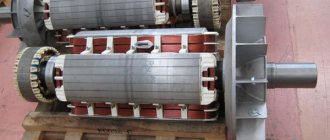
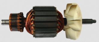
Winding of phase rotors
The winding of phase rotors is carried out using loose and rod ones. Random windings are loop three-phase two-layer equal-coil windings with a shortened pitch, similar to stator random windings. The winding connection is a star. Random-wound rotors are typically designed to have a line-to-line voltage of approximately 380 V.
The advantages of random windings on the rotor include: increasing the rotor voltage to the stator voltage and a corresponding decrease in the rotor current, and therefore reducing the size of the contact-brush assembly, improving the operation of the starting and control equipment; the possibility of reducing the number of rotor slots and a corresponding reduction in the consumption of insulating materials; the possibility of mechanizing the laying of the wound rotor winding.
Random windings of phase rotors
used for motors with power up to 50 kW. The grooves are usually trapezoidal or pear-shaped, semi-closed, as shown in Fig. 10, a, b.
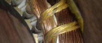
The core windings of phase rotors are two-layer wave windings. They are formed by rods of rectangular copper wire placed in rectangular semi-closed grooves of the rotor. Two rods are placed in each groove (Fig. 10, c), pre-insulated.
Rice. 10. Grooves of phase rotors
of the phase rotor winding coils
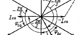
are divided into loop and wave. In the loop winding (Fig. 11), loop-shaped movements occur, and in the wave winding (Fig. 12), wave-shaped movements occur as each phase is bypassed. The stator windings of motors with voltages up to 0.66 kV for general industrial use are made only as loop windings. In the frontal parts the rods are bent (Fig. 12) so that two rods form a wave winding section. The pitch of the winding on the side of the slip rings (from the side of the winding terminals) is called the front unit or y1, and on the opposite side - the rear one y3 or y2. The sum y1+y2 is double pole division 2τ. An example of such a winding is shown in Fig. 12, where y1=y2=9, y1+y2=18, 2τ = 18.
Rice. 11. Detailed diagram of a two-layer loop winding: z1=48; 2р=8; y1=5; τ=6; β=5/6
With an integer number of slots per pole and phase, first perform q rounds in one direction, connect the two lower rods (jumper in Fig. 12) and make q rounds in the opposite direction. This creates each rotor phase winding.
Rice. 12. Detailed diagram of a two-layer wave winding: z2=36; 2р=4; y1=y2=9; τ=9
Recently, wave winding of phase rotors
, which does not require special jumpers for intermediate connections when performing a bypass rotation, as was the case in the previous case. Rotation is carried out for each phase winding using an oblique rod that passes from one layer of the groove to another. Some field distortion in this case does not have a significant effect on the operation of the asynchronous motor.
Rod windings are used for medium and high power motors with a voltage on the slip rings of 250-500 V. These windings are more labor-intensive to manufacture than random windings, due to the presence of a large number of solders and a large amount of manual work.
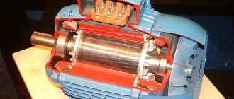
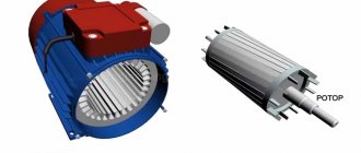
General characteristics of the stator
The motor stator, in turn, includes a frame into which an element such as an electromagnetic core is mounted. Its main task is to include a magnetic drive and a three-phase distributed stator winding. The core is responsible for the magnetization of the unit, as well as for the creation of a magnetic field in constant rotation.
In all types of asynchronous electric motor construction, the stator magnetic wires (cores) are made of layers of electrolytic steel, the thickness of which does not exceed millimeters. If the equipment is of low power, then the layer can have a thickness of 0.65 mm.
All sheets are isolated from each other by one of two methods: varnishing or oxidation. It is also quite common to use steel with an already applied electrical insulating coating.
The magnetic wire provides low magnetic resistance for the flow of magnetic pulses that are generated by the stator windings. Providing magnetization enhances the flux.
Example of a stator magnetic drive
A distributed winding into three phases for the stator is placed in the magnetic grooves. The simplest winding implementations consist of three phase coils, whose axes are shifted relative to each other by a level of 120 degrees. Next, these coils are connected to each other according to two already known schemes: “triangle” or “star”.
Connection of phase windings
There is another concept that plays an important role in the operation of the stator of an asynchronous motor - the distance between the rotor and stator, the gap. Its value directly affects indicators not only of an energetic nature, but also of vibroacoustic ones. When the gap decreases, the reactive component of the current for engine operation at idle speed also decreases. Based on this, the level of magnetic dispersion and inductive reactance of the power unit increases. In asynchronous electric motors, the gap varies from 0.2 to 2 millimeters.
Connection diagrams
The connection of the stator and rotor windings of an electric motor is carried out according to one of two schemes: “star” or “delta”. When using the first scheme, some ends of the stator windings are connected to each other, and the others are supplied with three-phase voltage (380 volts). At the same time, it is worth paying attention that a motor with windings connected in a star method has less power when compared with another method.
Delta connections are implemented by connecting all stator windings in series. That is, each winding is connected at its end to the beginning of the next coil. Switching engine components according to this scheme will provide an order of magnitude greater operating power, as full as possible. At the same time, the starting currents in such a circuit are quite high, which is why it is recommended to use a “star” to start the equipment, and then switch to a “delta” during operation.
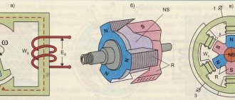
Current generator device
Greetings to everyone on our website. Today we will talk about the design of a current generator. Let's try to cover this topic as much as possible and consider the design of direct and alternating current generators.
In fact, it is not entirely correct to call this device an alternating or direct current generator, since current occurs only in a closed circuit. In general, EMF, not current, occurs in the generator windings. Current begins to flow only when any consumer is connected to the windings. However, in this article we will use established concepts.
Whatever electric generators are, their main principle is the generation of electrical energy due to the rotation of the winding in a magnetic field. This means that we can distinguish two schematic types of generators: either we rotate a magnetic field in a stationary conductor, or we rotate a conductor in a stationary magnetic field.
Electric motor stator windings, classification, characteristics, application
The stator windings of various types and types of AC electrical machines are varied in design, technology of their manufacture and placement in the grooves.
In order to more clearly imagine the existing const.
parts of stator winding coils of AC machines, as well as
due to the fact that the technological characteristics depend on the type and type of coils
all operations performed when repairing windings should be
conduct a conditional classification of electric stator winding coils
electrical AC machines for a number of structural and technological
gical signs.
Rated voltage up to 660 V, 3 kV and higher is widespread in the voltage class up to 660
IN
have
also around the perimeter of each turn (turn insulation). The ratio of the area of conductor and insulating materials to the cross-sectional area of the groove for low- and high-voltage windings can be estimated from Fig. 3. In addition, when producing coils with machine voltages of 10 kV and above, so-called anti-corona measures are applied, which consist of either being installed in
16 special structural elements inside the coils, or in applying additional coating to the outer surface of the coil insulation with semi-conducting varnishes.
The type of winding wire from which the coils are made. Coils made of round winding wire are soft coils, the final molding of the frontal parts of which is carried out during their placement in the stator slots, used for low-voltage asynchronous motors with a power of up to 100 kW. Coils made of rectangular winding wire are rigid coils that fit into the stator slots in a form that is finally molded during their manufacture and are used in high-voltage electrical machines. It should be noted that there are a number of standard sizes of low voltage electrical machines, which also use rigid coils - these are asynchronous and synchronous motors in the power range of 100-400 kW.
Heat resistance class. Depending on the calculated electromagnetic loads in starting and nominal modes and the associated temperature factors, as well as on the operating conditions, the windings of electrical machines in accordance with GOST 183-74 can be manufactured according to heat resistance classes A, E, B, F and H. Technologically this means the use for the winding of each heat resistance class of the corresponding brands of winding wires and insulating materials that can operate normally at temperatures characterizing this class.
The characteristics of the main groups of insulating materials and winding wires belonging to certain heat resistance classes will be given below with a direct consideration of the technological processes for manufacturing coils.
The number of sides of the coils in the groove.
The difference between the windings on this basis is that in a single-layer winding the side of the coil occupies the entire stator slot at the height, and in a double-layer winding it occupies only half of the slot. In terms of design and manufacturing technology, coils of single-layer and double-layer windings made from round wire (for motors up to 100 kW) do not have any fundamental differences. Single-layer and double-layer winding coils, made from winding wires of rectangular cross-section, are fundamentally different from each other in design, manufacturing technology, as well as in the technology of their laying and installation in the stator.
Type of winding elements.
The difference between the winding elements on this basis is that the coil can be technologically made closed with a series connection, in which case the winding is called a coil winding) or element, the windings are made in the form of rods, and the connection of the turns of the rods into a coil is made during the installation of the winding
torus; such windings are called core windings.
Each of the types of coils of windings of alternating current electrical machines is given a conditional classification due to various technological and operational factors and has
within a given type there are differences in design and materials used.
The high-voltage windings of stators, which are most widely used at present, according to the above classification, include: two-layer coil windings made of exchangers. precision wires of rectangular cross-section, for rated voltage. 3, 6 and 10 kV with insulation of heat resistance classes B, F and H Such windings are used in the vast majority of synchronous and asynchronous electrical machines with a power of 100-6000 kW, which make up the main fleet of high-voltage electrical machines in the country. In connection with the chosen type of windings, you should familiarize yourself with the construction of stator winding diagrams of electrical machines in which these types of windings are used.
Single phase asynchronous motor
A three-phase asynchronous motor was considered above; there are two of them in a single-phase asynchronous motor. One is working, the second is auxiliary. The auxiliary is needed in order to give initial rotation to the rotor. Therefore it can also be called starting or starting.
A single-phase asynchronous motor has two windings: working and auxiliary (starting or cranking)
When one winding in the stator is turned on, it creates two equal magnetic fields rotating in different directions. If you introduce a rotor into this field that already has some initial rotation, the magnetic field will maintain this rotation. But how to start the rotor at the start? How to give it rotation, because from one winding two equal magnetic fields arise, directed in different directions. So it is impossible to make the rotor rotate with their help. In the simplest version, rotation is set manually - mechanically. The rotation then picks up the field.
To automate the start of a single-phase asynchronous motor, an auxiliary winding was made. It is designed in such a way that it suppresses one of the components of the magnetic field of the main winding and enhances the second. Accordingly, one of the components outweighs, setting the rotation of the rotor. Then the starting winding is turned off, and the main winding maintains rotation.