Resistors
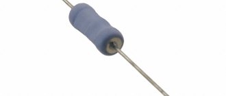
Rice. 1. Resistors
Resistors (Fig. 1) are two-terminal components used to limit current, divide voltage, and form the timing characteristics of circuits. They are used in conjunction with active components such as operational amplifiers, microcontrollers or integrated circuits and perform various functions such as biasing, filtering and pulling up I/O lines. Variable resistors can be used to change circuit parameters. Current-sensing resistors are used to measure currents in electrical circuits.
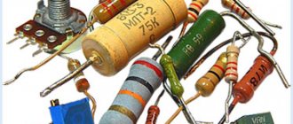
Types of resistors
There are several different types of resistors, varying in power rating, size, performance, and cost. The most common types are chip resistors (SMD resistors), through-hole resistors, wirewound resistors, shunts (current sensing resistors) for current sensing, thermistors, and potentiometers. Below, for each type of resistor, the main characteristics, the most suitable applications are presented, as well as information on housing designs and examples of specific series.
Features of the selection and use of resistors in power engineering
The apparent simplicity and obviousness of the use of resistors gives developers of power conversion equipment the misleading impression of the small influence of resistors, as extremely simple devices from the point of view of circuit design, on the resulting reliability of the device being developed. However, this is not the case, and the use of resistors, like any other component, requires careful consideration in selecting types and ensuring favorable operating conditions.
To better understand the operating features of resistors, let's turn to basic concepts. A resistor, as an element of an electrical circuit, serves to create resistance to the flow of electric current. Ideally, the operation of a resistor is determined by a fundamental law established by the German physicist Georg Simon Ohm and bearing his name:
where R is the electrical resistance of the circuit section; U is the voltage applied to the circuit section; I is the current flowing in the circuit.
When current flows through a resistor, the energy of the ordered movement of charge carriers is converted into heat and dissipated in the surrounding space due to heat transfer and radiation. The power released in the resistor can be determined by the formula following from Ohm's law:
or
Here P is the power released in the circuit section; R is the electrical resistance of the circuit section; U is the voltage applied to the circuit section; I is the current flowing in the circuit.
The power released in the resistor causes its temperature to rise. The maximum temperature that a resistor can withstand without damage depends on the design of the resistor and the materials used - both the resistive element itself and its fittings. It is the maximum temperature of the hottest section of the resistor that determines the power that the resistor is capable of dissipating.
Depending on the conditions in which the resistor is located (temperature, humidity, ambient air pressure and the speed of its movement), the same dissipated power causes a different increase in the temperature of the device, therefore, when choosing a resistor, it is important not only to determine the allocated power, but also its conditions work. The rated power of the resistor is defined as the power dissipated by the device without exceeding the maximum permissible temperature with natural air cooling at an altitude of 0 m above sea level at an air temperature of 25 ° C.
When operating a resistor, it should be remembered that the released power has a quadratic dependence on the voltage applied to the resistor or on the flowing current (Fig. 1).
Rice. 1. Dependence of the released power on the voltage (current) of the resistor
This means that a small increase in voltage or current in the circuit will cause a significant increase in power dissipation, which can exceed the maximum allowable for the resistor used, which will lead to failure of the device. Therefore, when choosing a resistor, it is important not only to know the rated current and voltage for it, but also to take into account possible long-term deviations, in particular due to fluctuations in the supply voltage.
If the power dissipated by the resistor is constant, then after some time the temperature of the resistor will stabilize (when the amount of heat generated in the resistor becomes equal to the amount of heat given off by the resistor to the environment through radiation, convection and heat transfer from the structure). The larger the physical size of the resistor, the more efficiently the heat transfer process occurs and the lower the equilibrium temperature will be at the same power output. In addition, the efficiency of radiation, convection and heat transfer depends significantly on the resistor design, materials used and cooling conditions.
The values of the maximum power dissipation of resistors given in the reference materials refer to free cooling conditions. Today, there are a number of standards regulating the method for determining the maximum permissible power dissipation of resistors based on the overheating temperature of the hottest section of the resistor. Leading manufacturers of high-power resistors (Danotherm, Ohmite, Arcol, SIR, etc.) usually follow the recommendations of the National Electrical Manufacturers Association (NEMA) and Underwriters Laboratories, Inc. when regulating the power of their devices. (UL). According to these, the maximum permissible power during natural cooling for a resistor of given physical characteristics and dimensions is defined as the power that causes the temperature (measured by a thermocouple) of overheating of the hottest section of the resistor to be 300 °C at an ambient temperature of 40 °C. The measurement is carried out in still air under conditions of free convection and the resistor is removed from the nearest object (in particular, walls, panels, devices) by at least 35 cm.
Slightly different measurement conditions are determined by the MIL-R-26 standard, originally developed for wirewound resistors for military and aerospace applications, and then extended to devices for industrial and commercial use. According to this standard, the maximum heating temperature of the hottest section of the resistor is set to 350 °C at an ambient temperature of 25 °C. Thus, the corresponding superheat temperature is 325 °C.
In Fig. Figure 2 shows average graphs of the overheating temperature of resistors according to various standards depending on the relative power dissipation.
Rice. 2. Dependence of the resistor overheating temperature on the relative power dissipation
To a first approximation, the temperature of a resistor depends on its surface area, and also (to a lesser extent) on a number of other factors, such as the thermal conductivity of the base and coating of the resistor, the radiation efficiency of the surface, the ratio of the resistor's length to its diameter, heat transfer through the terminals and mounting means.
The maximum permissible temperature of the resistor will be determined by the properties of its structural materials and is the limit value, above which the device may become inoperable. In the general case, this value can be used only to calculate the maximum operating modes of the device.
Under normal operating conditions, one should take into account not only and not so much the physical functioning of the resistor, but also other parameters, such as changes in resistance with increasing temperature, heating of devices surrounding the resistor due to the heat generated by it, dependence of resistance on ambient humidity (especially for resistors open types), changes in characteristics under cyclic load, etc.
If the ambient temperature differs (increasingly) from 25 °C (or 40 °C), then the power dissipated by the resistor should be correspondingly reduced to values at which the maximum permissible heating temperature of the device is not exceeded. In Fig. Figure 3 shows graphs of the relative power dissipation of resistors versus ambient temperature according to NEMA, UL and MIL-R-26 (U-EIA) recommendations.
Rice. 3. Dependence of the relative power dissipation of the resistor on the ambient temperature
When constructing these dependencies, it is assumed that the overheating temperature does not depend on the ambient temperature. However, this is not entirely true. An accurate calculation must take into account the increase in radiation efficiency with increasing temperature according to the Stefan-Boltzmann and Wien laws. But the contribution made due to this at low temperatures (up to 1000–1500 °C) is very small, and it can be ignored in the vast majority of design calculations.
For some types of resistors, the reference data indicates the maximum permissible thermal load of the surface. For most types of wirewound resistors, it ranges from 0.7 W/cm2 (for large resistors with a power of more than 150–200 W) to 2 W/cm2 (for small resistors with a power of 10–20 W). This value is convenient to use when calculating the operation of a resistor as a heating element.
Please note that the recommendations for determining the maximum power of resistors do not indicate the location of the resistor relative to the ground surface. But there is a clear indication that the temperature is measured for the hottest section of the resistor. For a horizontally located tubular wirewound resistor with uniform winding of the resistive element, the temperature in the middle of the device can be 1.5–2.5 times higher than the temperature at the ends (depending on the mounting method). When positioned vertically, the maximum heating zone shifts upward by 3–10% of the length of the resistor, and the upper end has a higher temperature than the lower end. This causes a slight increase in mechanical stress in the device structure and may reduce its reliability. Therefore, all other things being equal, you should always prefer the horizontal arrangement of resistors, with the exception of devices specially designed for vertical installation, for example, in heat-sinking housings made of aluminum profiles. For a number of special applications (for example, as a uniform heat source), special resistors are produced with uneven winding of the resistive element (more frequent at the edges and rarer in the middle), in which the temperature is almost constant along the entire length of the device.
Let us consider in more detail the main factors that determine the temperature of the resistor, or, on the other hand, the required value of rated power at which the temperature does not exceed the specified one:
1. Ambient temperature
An increase in ambient temperature causes a corresponding decrease in the permissible overheating temperature and the corresponding dissipation power. The dependence of the relative permissible power dissipation on the ambient temperature is shown above, in Fig. 3. If the ambient temperature is lower than that for which the maximum dissipation power was determined (25 ° C or 40 ° C), then in some cases it is possible to allow the maximum power to increase above the typical value, but in this case it is necessary to further clarify the resistor’s capabilities for working with currents exceeding the rated current. Exceeding the resistor current in this case may not cause an increase in its temperature above the maximum permissible, but the destruction of external and internal contacts (the junction of the resistive element with the terminals) and local overheating and melting of the resistive element.
2. Installation in a closed housing
Installing a resistor in the housing worsens the conditions for heat removal due to radiation (part of the radiation is reflected by the walls of the housing, the rest is emitted both into the surrounding and into the internal space of the housing), as well as due to convection (the housing disrupts the convection flow of air and blocks the access of cold air to resistor). The temperature of the resistor placed in the housing is significantly influenced by the size, wall thickness, their material and the presence of perforations and surface coloring. The deterioration of the operating conditions of the resistor when placed in a housing is clearly demonstrated by the graphs in Fig. 4.
Rice. 4. Dependence of resistor overheating temperature on power when installed in free space and in housings of different sizes
3. Installation of groups of resistors
Resistors mounted at a short distance from each other heat up more during operation than a single resistor with the same power dissipation (on each of the resistors in the group). This occurs due to mutual heating of the resistors by radiation and an increase in the amount of heat per unit volume of cooling air during natural convection. In order to ensure that the temperature of resistors operating in a group does not exceed the permissible value, it is necessary to reduce the power per each of the devices in relation to the maximum permissible for one freely installed resistor. Rice. 5 gives an idea of the order of the required reduction in power dissipation on each of the resistors, depending on the number of resistors in the group and the distances between them.
Rice. 5. Dependence of the permissible power dissipation of each resistor in the group on the number of resistors and the distances between them
4. Altitude
The amount of heat removed from the resistor due to air convection depends on the density of the latter. The thinner the air, the less heat it can remove. As you rise in the atmosphere, the density of the air decreases, which means that the maximum power dissipation of the resistors will decrease. At altitudes above 20,000 m, the air density is already so low that convective heat removal ceases to play any significant role in the overall thermal balance of the resistor and heat is removed only through radiation and heat transfer to structural elements. In Fig. Figure 6 shows a graph of the dependence of the relative power dissipation of the resistor on the height of its placement (above sea level).
Rice. 6. Dependence of the relative permissible power dissipation of the resistor on altitude above sea level
5. Work in pulse modes
If current does not flow through the resistor constantly, but during certain time intervals, and at other times the resistor is de-energized, then the amount of heat generated over a significant period of time will be less than during continuous operation. “Averaging” over time occurs due to the heat capacity of the structure, mounting elements and surrounding air. As a result, the temperature of the resistor does not exceed the maximum permissible even at pulse powers many times higher than the maximum power of continuous mode. The amount of permissible pulse power depends both on the design features of the resistor (heat capacity and thermal conductivity of the structure), and on the pulse duration and the ratio of pulse and pause durations (duty factor). In Fig. Figure 7 shows the relative permissible pulse power dissipation for various types of resistors, determined according to NEMA recommendations for starting and braking resistors.
Rice. 7. Dependence of the relative pulse permissible power dissipation of the resistor on the duty cycle of the current pulses for the standard starting mode of the electric motor
For a number of types of resistors, the pulse power is limited not by permissible overheating, but by the maximum value of the operating current of the resistor, if exceeded, damage to the resistive element and terminals is possible due to local overheating.
Graphs in Fig. 8 give an idea of the process of heating resistors of different types with a current pulse and are plotted in coordinates of the pulse time required to heat the resistor to the maximum permissible temperature and pulse power.
Rice. 8. Dependence of the time required to heat the resistor to the maximum permissible temperature on the relative pulse power dissipation
Using the dependencies presented in Fig. 9, it is possible to determine the ratio of the pulse durations and pauses of the current through tubular resistors, heating the devices to the maximum permissible temperature for various absolute durations and various relative pulse powers (as a percentage of the maximum permissible power dissipation of the continuous mode).
Rice. 9. Dependence of current pulse and pause times and their ratios required to heat the resistor to the maximum permissible temperature on pulse power
The features of pulse modes discussed above relate to typical pulse modes that occur when using resistors in the starting and braking circuits of electric motors, where the times of exposure to significant currents are calculated in units and tens of seconds, and pauses - from units of seconds to many hours.
For pulsed currents of short duration (0.1–0.5 s or less), the pulse characteristics will differ significantly from those given above, since they will be determined to a greater extent by the thermophysical properties of the resistive element rather than by the heat capacity of the entire resistor as a whole. At even shorter pulse durations (less than a few milliseconds), the inductance of the resistor begins to play an important role, increasing the total resistance of the resistor in the region of small times. For use at frequencies above 1–3 kHz (pulse durations less than 1 ms), special resistors are manufactured with bifilar winding, which sharply reduces the resistor’s own inductance, or surface and volume resistors based on conductive films.
6. Forced cooling
Forced blowing of resistors sharply increases the amount of cooling air compared to the natural convective flow and, thereby, makes it possible to increase the efficiency of heat removal. This is a very simple and extremely effective way to increase the permissible power dissipation of resistors. In Fig. Figure 10 shows the dependence of the relative permissible power dissipation on the speed of the air cooling the resistor.
Rice. 10. Dependence of the relative permissible power dissipation of the resistor on the cooling air speed
The effectiveness of this simple measure can be judged by the fact that at an air speed of only 2.5 m/s, the power dissipated by the resistor without overheating is more than twice its maximum power with natural cooling. If resistors operate, for example, in rheostatic braking systems of electric rolling stock, then in order to save energy, it is possible to use not constant blowing, but one associated with the braking process, when fans are connected in parallel with the braking resistor or its outlet. Such cooling circuits for braking resistors are used on a number of mainline electric locomotives of domestic and foreign production.
7. Resistor temperature limitation
In some cases, in order to increase reliability and increase the service life of equipment, the operating temperature of resistors is chosen below the maximum permissible. Reducing the surface temperature of the resistor by 2 times relative to the maximum permissible increases the reliability of the resistor from 4 to 100 times (depending on the type), and also reduces the temperature inside the device in which the resistor is installed, which is also an extremely favorable factor. Unfortunately, a decrease in the temperature of fuel elements, all other things being equal, is always associated with an increase in their physical dimensions, so this measure can be recommended only if it is allowed by the weight and size parameters of the equipment.
Considering all of the above, for the initial selection of a resistor, we can recommend using the data from the mnemonic table shown in Fig. 11. Each of the 7 columns of the table shows the values of the coefficients for various environmental conditions and operating modes. If the power dissipated by the resistor is known (from the calculation of the electrical circuit), then by multiplying it by the coefficients determined from the table and corresponding to the conditions and modes of operation, you can obtain the value of the rated power of the resistor, which should be used in this circuit under these conditions.
Rice. 11. Table for determining the required rated power of the resistor
As an example, we will determine the rated power of the resistor for the electric motor starting system. The pulse power released on the resistors according to the calculation is 1 kW (300% of the nominal), dissipated in a group of 4 resistors (250 W per resistor), the ambient temperature is +60 ° C, the resistors are mounted in an open rack, the distance between the resistors 5 cm, it is assumed that the device can operate at an altitude of up to 4000 m above sea level, natural convection cooling, resistor temperature is limited to 250 °C.
We determine the corresponding coefficients from the table:
The rated power of each of the resistors in the group will be:
Thus, the rated power of each resistor in the group must be at least 160 W.
Of course, calculating the rated power using this table is approximate, since it does not take into account many additional factors, however, its error is quite small and allows you to quickly determine the power of the required resistor, and based on it, the specific type of device used.
Despite the fact that resistors, in fact, are the simplest elements of electrical circuits, the reliability, cost and performance of the equipment largely depend on the correct choice of their types and operating conditions, and the correct choice of resistors for power converter devices, made at the design stage, in will largely determine the commercial fate of the equipment.
When preparing the article, information materials from the companies Danotherm (Denmark), Arcol (UK), Ohmite (USA), SIR (Italy) were used.
Literature
- www.danotherm.com/
- www.ohmite.com/
- www.sirresistor.it/
- www.arcolresistors.com/
- Resistors: Handbook / Ed. I. I. Chertvertkova. M.: Energoizdat. 1981.
- GOST 24238-84 Constant resistors. General technical conditions.
- GOST 28608-90 (IEC 115-1-82) Fixed resistors for electronic equipment.
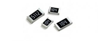
SMD resistors
Rice. 2. Chip resistors
Chip resistors (Fig. 2) are designed for surface mounting. They differ from output resistors in being smaller in size, which makes them optimal for use on printed circuit boards. The most common tasks of SMD resistors are pulling up I/O ports, dividing voltage, and limiting current. Resistors are also used as part of high-pass/low-pass/band-pass filters. Zero resistance resistors can be used as jumpers to switch various circuits.
There are two types of SMD resistors:
- Thin film resistors are commonly used in a variety of precision applications such as audio, medical, or test equipment. They are characterized by a minimal spread of ratings (0.1 ... 2%), low temperature coefficient (5 ppm/C) and lower noise levels compared to thick film resistors. However, their cost is higher.
- Thick film resistors are the most common type of resistor and are used for a wide range of applications. They are characterized by a higher resistance error (typically 1 ... 5%), an increased temperature coefficient (50 ppm/C) and a higher noise level compared to thin film resistors. If there are no special requirements for the resistor, then a thick film resistor is usually the preferred choice.
Housing versions : the most common standard sizes of SMD resistors are 0201, 0402, 0603, 0805 and 1206. The numbers indicate overall dimensions in the inch system, for example, housing 0402 has dimensions of 0.04x0.02″, housing dimensions 0603 are 0.06x0.03 " and so on.
Examples:
- 0402 - RC0402FR series manufactured by Yageo with a rated power of 0.063 W (1/16 W) and a range of available resistances of 1 Ohm ... 10 MOhm;
- 0603 - RC0603FR series from Yageo with a nominal power of 0.1 W (1/10 W) and a range of available resistances of 1 Ohm ... 10 MOhm;
- 0805 - RC0805FR series from Yageo with a rated power of 0.125 W (1/8 W) and a range of available resistances of 1 Ohm ... 10 Mohm;
- 1206 is the RC1206FR series from Yageo with a nominal power of 0.25 W (1/4 W) and a range of available resistances of 1 Ohm ... 10 MOhm.
Or
- 0402 - CR0402 series manufactured by Bourns with a nominal power of 0.063 W (1/16 W) and a range of available resistances of 1 Ohm ... 10 MOhm;
- 0603 - CR0603 series from Bourns with a nominal power of 0.1 W (1/10 W) and a range of available resistances of 1 Ohm ... 10 MOhm;
- 0805 - CR0805 series from Bourns with a power rating of 0.125 W (1/8 W) and a range of available resistances of 1 Ohm...10 MOhm;
- The 1206 is the CR1206 series from Bourns with a power rating of 0.25 W (1/4 W) and a range of available resistances from 0.82 ohm...10 megohm.
Or
- 0402 - CRCW0402 series manufactured by Vishay with a rated power of 0.063 W (1/16 W) and a range of available resistances of 1 Ohm ... 10 MOhm;
- 0603 - CRCW0603 series from Vishay with a nominal power of 0.1 W (1/10 W) and a range of available resistances of 1 ... 15 MOhm;
- 0805 - CRCW0805 series from Vishay with a nominal power of 0.125 W (1/8 W) and a range of available resistances of 1 Ohm ... 50 MOhm;
- 1206 - CRCW1206 series from Vishay with a power rating of 0.25 W (1/4 W) and a range of available resistances from 1 Ohm...100 MOhm.
Which side to count the stripes on the resistor?
The resistance of the resistor is determined by the first color rings:
- For elements with three stripes, the first two colors are numbers, and the third color is the multiplier.
- For elements with four stripes, the first two colors are numbers, the third color is the multiplier, and the fourth color is the permissible deviation of the resistor resistance from its nominal value.
- For elements with five stripes, the first three colors are numbers, the fourth color is the multiplier, and the fifth color is the permissible deviation of the resistor resistance from its nominal value.
- For elements with six stripes, the first three colors are numbers, the fourth color is the multiplier, the fifth color is the permissible deviation of the resistor resistance from its nominal value, and the sixth is the temperature coefficient.
The color markings on resistors are read from left to right. In this case, you need to correctly determine the left side. As a rule, the first stripe is applied closer to one of the resistor terminals. If the element is small in size and it is impossible to maintain the required proportions for marking delimitation, then the counting is based on the color stripe, which is the widest in comparison with the others.
Additionally, it can be noted that silver and gold colors are never used to indicate the first stripes on resistors. And, as can be seen from the calculation tables, digital values are not specified for these colors.
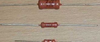
Through-hole Terminal Resistors
Rice. 3. Lead-in resistors for through-hole mounting
Axial-lead through-hole resistors (Figure 3) are very popular and widely used, especially in prototyping, as they are easy to replace when working with breadboards. Like chip resistors, pin resistors are used for pull-up, voltage division, current limiting, and filtering. There are different types of output resistors. The most popular are carbon film and metal film resistors.
- Carbon film resistors have a significant variation in resistance (2...10%). The most common resistance series for these are E12 (±10%), E24 (±5%) and E48 (±2%). In most applications, carbon film resistors have been replaced by metal film resistors. The temperature coefficient of resistance of carbon film resistors (TCF) is typically negative, around -500 ppm/C, but the specific value depends on the resistance and size.
- Metal film resistors have a smaller resistance spread (0.1...2%) and higher stability. The most common resistance series for these are E48 (±2%), E96 (±1%) and E192 (±0.5%, ±0.25% and ±0.1%). Since metal film resistors have better performance than carbon resistors, they are used in most applications. The temperature coefficient of metal film resistors (TC) is approximately ±100 ppm/C, however some models have only positive or only negative TC.
- Carbon composite resistors were widely used in electronic devices fifty years ago, but due to wide variation in values and poor stability, they have been replaced by carbon film and metal film resistors. However, composite resistors have good high-frequency characteristics and can withstand high-power pulses, which is why they are still used in welding equipment and high-voltage power supplies.
- Metal oxide resistors were the first alternative to carbon composite resistors, but have since been replaced by metal film resistors in most applications. However, because metal-oxide resistors have higher operating temperatures and higher power ratings (> 1 W), they are still used in critical applications operating in harsh environments.
The EIA (EIA Decade Resistor Values) series of resistances determine not only the resistor values, but also the permissible error. For example, the E12 series (±10%) includes the following standard values: 100, 120, 150, 180, 220, 270, 330, 390, 470, 560, 680 and 820 ohms.
Color coding is used to encode the parameters of the output resistors (Table 1).
Table 1. Color coding of output resistors
| Color | Meaning | ||||||
| First digit | Second digit | Third digit* | Factor | Accuracy | Temperature coefficient, ppm/C | Failure Rating | |
| Black | 0 | 0 | 0 | x10^0 | — | — | — |
| Brown | 1 | 1 | 1 | x10^1 | ±1% | 100 | 1% |
| Red | 2 | 2 | 2 | x10^2 | ±2% | 50 | 0,1% |
| Orange | 3 | 3 | 3 | x10^3 | — | 15 | 0,01% |
| Yellow | 4 | 4 | 4 | x10^4 | — | 25 | 0,001% |
| Green | 5 | 5 | 5 | x10^5 | ±0,5% | — | — |
| Blue | 6 | 6 | 6 | x10^6 | ±0,25% | — | — |
| Violet | 7 | 7 | 7 | x10^7 | ±0,1% | — | — |
| Grey | 8 | 8 | 8 | x10^8 | ±0,05% | — | — |
| White | 9 | 9 | 9 | x10^9 | — | — | — |
| Gold | — | — | — | x0.1 | ±5% | — | — |
| Silver | — | — | — | x0.01 | ±10% | — | — |
| Empty | — | — | — | — | ±20% | — | — |
| *Only for resistors with 5-position markings | |||||||
Examples:
- carbon film resistors of the CFR-25JB series manufactured by Yageo with a rated power of 0.25 W and a range of available resistances of 1 Ohm...10 MOhm;
- metal film resistors of the MFR-25FBF series from Yageo with a rated power of 0.25 W and a range of available resistances of 10 Ohm...1 MOhm;
- metal film resistors of the PR02 series from VISHAY with a rated power of 2 W and a range of available resistances of 0.33 Ohm...1 MOhm.
Universal color chart
There is a universal color table that allows you to quickly calculate the values of each resistor if necessary.
When creating such a table, the following fields are selected:
- The color of the ring or dot applied. In this case, both the name and an example are given.
- Depending on the value of the color, it is possible to convert the color coding into a numerical value. This is necessary when creating a diagram for symbolizing denominations.
- The multiplier allows for a mathematical calculation of what resistance the design in question has.
- Also, for almost every color there is a field that indicates the maximum deviation from the nominal value.
It is worth remembering that each color can indicate a number in the marking, a multiplier value, or a maximum deviation.
Examples
Example 1:
Let us consider the use of such a table using the following example: brown, black, red, silver. We read the rings from left to right, the resulting value is always encoded in Ohms.
According to the data from the table, we carry out the following decoding:
- The brown color in the first position represents both the digit and the multiplier. In this case, the number will be “1” and the multiplier “10”. It is worth noting that the following colors cannot be used in the first position: black, gold or white.
- The second color means the number of the second digit. Black means "0" and is not used in calculations. Having such data, we can conclude that the resistor has the alphanumeric marking 1K0.
- The third color determines the multiplier. In our case, it is red, the multiplier of this color is “100”.
- The last color means the maximum tolerance for deviation, and the silver color corresponds to 10%.
Using the table, we can say that the resistor in question is marked 1K0 and has a resistance value of 1000 Ohms (10*100) or 1 kOhm, as well as a tolerance of 10%.
Example 2:
Another more complex example is the calculation of the nominal values of the following resistor: red, blue, purple, green, brown, brown. This marking consists of 6 rings.
When decrypting, we note the following:
- 1 ring, red – number “2”.
- 2nd ring, blue – number “6”.
- 3rd ring, purple – number “7”.
- We select all numbers from the table. When they are combined, we get the number “267”.
- 4 ring is green. In this case, we pay attention not to the numerical value, but to the multiplier. Green color corresponds to a multiplier of 105. We carry out the calculation: 267 * 105 = 2.67 MOhm.
- 5 ring is brown and corresponds to a maximum deviation of 1% in both directions.
- Line 6 is brown, which corresponds to a temperature coefficient of 100 ppm/°C.
From the above example, we can say that deciphering the markings is not difficult, and the number of rings has virtually no effect on how complex the calculations will be. In this case, the resistor has a resistance of 2.67 MΩ with a deviation in both directions of 1% at a temperature coefficient of 100 ppm/°C.
The procedure can be simplified by using special calculators. However, not many people do the 6 ring calculation, which is worth considering.
The nominal series of resistors can be called the result of standardization of nominal values. Fixed resistors have 6 similar rows. Also, one row for variable denominations and a special row E3 have been introduced.
Using the example given denomination, let's decipher it:
- The letter “E” means that marking is carried out according to a series of denominations. This beech is always included in the designation.
- The numbers after the letter indicate the number of nominal resistance values in each decimal interval.
There are special tables displaying nominal series.
To identify standard series, GOST 2825-67 was adopted. At the same time, we can highlight several of the most popular standard series:
- Row E6 has a deviation in both directions of 20%.
- Row E 12 has a permissible deviation of 10%.
- The E24 series has a maximum permissible deviation in both directions of 5%.
The subsequent rows E48 and E96, E192 have a deviation rate of 2%, 1%, 0.5%, respectively.
Wirewound resistors
Rice. 4. Wirewound resistor
Wirewound resistors (Fig. 4) are structurally a high-resistance wire wound around an insulating core. They feature very high power ratings (up to 1000 W) and are capable of operating at very high temperatures (up to 300°C). Wirewound resistors are characterized by excellent long-term stability - about 15...50 ppm/year, while, for example, for metal film resistors this figure is 200...600 ppm/year. This type of resistor has the lowest noise level.
Disadvantages : the range of available resistances for wirewound resistors is quite narrow (0.0001...100 kOhm). Since the resistor is made in the form of a wire wound on a base, this design is characterized by high parasitic inductance. For this reason, in the high-frequency range, wirewound resistors exhibit the worst performance of all types of resistors. They also happen to be more expensive compared to other popular types of resistors.
Applications : Commonly used in circuit breakers and as fuses due to their high power.
Examples
- KNP500 series manufactured by Yageo with a rated power of 5 W and a range of available resistances of 0.1 Ohm ... 2.2 kOhm;
- HS-25 series manufactured by Ohmite with a nominal power of 25 W and a range of available resistances of 0.01 Ohm ... 5.6 kOhm;
- HSC100 series from TE with a rated power of 100 W and a range of available resistances of 0.1 Ohm ... 50 kOhm.
Types of resistors according to the nature of resistance changes
Resistors can be fixed or variable.
Constants have two terminals and a stable resistance shown in the marking. In variable (regulating and tuning) resistors, this parameter varies within acceptable limits, depending on the operating mode.
There are three conclusions in the variable summaries. The diagram indicates the nominal value between the extreme terminals. The resistance value between the middle and outer terminals is adjusted by moving the sliding contact (slider) along the resistive layer. In this case, the resistance between the middle and one of the extreme terminals increases, and between the middle and the other extreme terminals it decreases. When the “runner” moves in the other direction, the effect is reversed.
What do trim resistors do?
They are designed for periodic adjustment, so the moving system is designed for a small number of movement cycles - up to 1000.
Adjustment resistors are designed for repeated use - more than 5 thousand cycles.
Current measuring resistors (shunts)
Rice. 5. Shunts
Current sense resistors, also called shunts (Figure 5), are used to directly convert current to voltage for further measurement. They are low resistance resistors with a high power rating, allowing them to handle high currents.
One application for current sensing resistors is to limit current to protect stepper motor driver ICs.
Most modern shunts have either two or four terminals. In the four-terminal version, also called a Kelvin circuit, current is passed through two terminals and voltage is measured at the remaining two terminals. This design reduces the influence of temperature errors and significantly increases the stability of the measurement circuit. Four-terminal resistors are used for applications requiring high precision and temperature stability.
Examples
Two-pin versions
- SMD:
- MCS1632 series manufactured by Ohmite with a nominal power of 1 W and a range of available resistances of 0.005 ... 0.05 Ohms;
- WSLP1206 series from Vishay with a rated power of 1 W and a range of available resistances of 0.005 ... 0.05 Ohms;
- CRA2512 series from Bourns with a rated power of 3 W and a range of available resistances of 0.001 ... 0.1 Ohms.
- For through-hole mounting:
- 12F series from Ohmite with a nominal power of 2 W and a range of available resistances of 0.001 ... 0.25 Ohms;
- LVR03R series from Vishay with a rated power of 3 W and a range of available resistances of 0.01 ... 0.2 Ohms;
- PWR247T-100 series from Bourns with a rated power of 100 W and a range of available resistances of 0.05 ... 100 Ohms.
Four-pin versions (Kelvin circuit)
- SMD:
- FC4L series in the 2512 package from Ohmite with a nominal power of 2 W and a range of available resistances of 0.001 ... 0.05 Ohms;
- WSL3637 series in 3637 package from Vishay with a rated power of 3 W and a range of available resistances of 0.001...0.01 Ohm.
Marking: designation
For the vast majority of the element base, radio factories resort to special markings with a certain color, but sometimes they use both digital and letter designations. For example, SMD resistive elements have only letters.
Color markings are 4...6 stripes of different colors, which carry certain information. The first 2 digits indicate the nominal resistance, and the 3rd, by which the first 2 are multiplied, ultimately demonstrate the total resistance value. The 4th indicates the accuracy class of the resistor. If there are more stripes, then only the 1st indicator changes by one digit.
Thermistors
Rice. 6. Thermistor
Thermistors are resistors whose resistance changes significantly with temperature changes (Fig. 6).
The resistance of NTC thermistors gradually decreases with increasing temperature. NTC are ready-made temperature sensors with a measurement range of -55… +200°C.
PTC thermistors are characterized by an abrupt change in resistance at a certain temperature. They are used as overcurrent protection elements.
PTC hold current is the current at which the thermistor is guaranteed to be conducting.
PTC trip current is the current at which the thermistor is guaranteed to become non-conducting.
Examples
- PTC thermistors:
- 1812 - MF-MSMF series manufactured by Bourns for operating currents from 0.3...5.2 A;
- 1812 - 1812L series from Littelfuse for operating currents 0.1...3.5 A.
- B57236 series from EPCOS with a resistance range of 2.5...120 Ohm;
- 0603 - ERT-J1 series from Panasonic with a resistance range of 0.022...150 kOhm.
Calculation of power dissipation
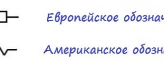
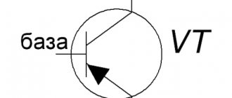
Symbols of resistors in the diagrams
In any of the options, when choosing the electrical resistance of the circuit, you should set a slightly lower current in order to extend the life of the LED. To prevent heat damage, use the product within the recommended temperature range. For Epistar 1W HP – from -40°C to +80°C. If necessary, use installation on a specialized “star” radiator. This addition increases the effective heat dissipation area.
For accurate selection, estimate the power dissipation of the resistor: P = I2 * R = (0.35)2 * 7.57 = 0.1225 * 7.57 ≈0.93 W. The reserve for this parameter is made at least 20-25%. The 1 W rating is not enough, so choose the next rating in the standard series - 2 W.
The efficiency of the assembled circuit is checked by the ratio Uc/Ui = 2.35/5 = 0.47 (47%). The final result shows that more than half of the electricity in this case is wasted. In fact, the indicator is even worse, since not all the power consumption is spent by the LED on radiation in the visible part of the spectrum. A significant part is electromagnetic waves in the infrared range.
Potentiometers and trim resistors
Rice. 7. Trimmer resistors
Potentiometers are resistors with variable resistance. They are used in various applications, such as controlling the gain of an amplifier, adjusting circuit parameters, and so on.
Trimmer resistors (Figure 7) are small potentiometers that can be mounted on a printed circuit board and adjusted with a screwdriver. They are available for both SMD surface mounting and through-hole mounting, with a top or side adjustment screw.
Potentiometers are available in single-turn and multi-turn types. Single-turn potentiometers are often used in amplifiers. Multi-turn potentiometers can have up to 25 turns and are used for more precise control.
Examples
- Single turn potentiometers:
- SMD series TC33X-2 manufactured by Bourns with a resistance range of 100 Ohm...1 MOhm;
- 3362P series from Bourns with a resistance range of 10 Ohm...5 MOhm;
- series 3296W from Bourns with a resistance range of 10 Ohm...5 MOhm;
- T93YA series from Vishay with a resistance range of 10 Ohm...1 MOhm.
Noises and ways to reduce them
Individual noise in resistors includes noise: thermal and current. Thermal noise is provoked by the movements of electrons in conductive layers and increases with increasing temperature of the part and the overall outside temperature. When current passes, current noise will be generated. Such noise, whose level is higher than that of thermal noise, is usually pronounced in non-wire resistive elements.
Noise elimination options:
- The use of resistive elements in electrical circuits, whose noise component is small, through the use of special production cycle technologies.
- Resistive elements of variable type have higher noise than constant ones. Consequently, circuits try to use variable resistors with minimal values as much as possible or avoid their use altogether.
- The use of resistive elements with higher powers than required according to preliminary calculations.
- Forced cooling systems for resistors through the installation of special fans.
Resistor assemblies
Rice. 8. Resistor assembly 4609X-101-222LF
A resistor network (resistors array) is a combination of several resistors placed in one housing. There are a large number of different types of these products, but, unfortunately, there is no clear system of their classification, both in the literature and among manufacturers.
Resistors inside the assembly body may not be connected to each other (Isolated), i.e., each resistor has two terminals on the assembly body, or configured in a specific circuit (Bussed). Often there are products in which pin 1 of each resistor is connected to one common pin of the assembly, and every second pin of the resistors has its own pin on the product body. In addition, you can find assemblies with series, series-parallel and other types of resistor connections inside the housing. Assemblies can be classified by the number of resistors included in them, by tolerance value, maximum operating voltage, power dissipation, standard size, mounting type (SMD and lead-out), etc. These components are very convenient to use in ADC and DAC circuits, used as voltage dividers, used in computer equipment, consumer electronics, etc.
Examples
- 4600X series from Bourns with operating voltage up to 100V
Rice. 9. Bourns 4600X Series Resistor Array Configuration
- CAY16 series from Bourns in SMD size 1206 package with isolated resistors
- Bourns 4114R-2 Series - 14 pin resistors with one common pin
R2 – 80 Ohm (1 W)
From all of the above, we can conclude that the different resistance of the resistors guarantees their different power output, since it is distributed between resistors of different ratings. If you do not take this circumstance into account, you may encounter a lot of difficulties. If one of the resistors is chosen incorrectly, the second one operates under severe temperature conditions. There is also a risk of the resistor catching fire due to non-compliance with power rules.
In order to save time and not have to calculate the power of each individual current resistor, you need to remember one simple rule: the power of the resistor being replaced must be equal to the power of each resistor that makes up the parallel or series circuit. That is, when replacing a 0.5 W resistor, you must ensure that each of the replacement resistors has a power of at least 0.5 W.
When connecting resistors in parallel, it is important to remember that the lower the resistance of the resistor, the greater the current flows through it, which means more power will be dissipated on it
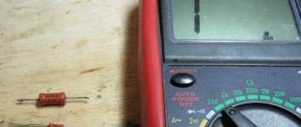
Tags: sconce, view, house, , protective, sign, how, design, , marking, marking resistor, installation, power, multimeter, voltage, nominal, strip, rule, principle, wire, start, , work, size, calculation , reves, resistor, row, light, system, connection, connection resistor, resistance, circuit, ten, type, current, , photo, shield, equivalent, electronic
Working with the Terraelectronics Catalog to search for resistors
There are two ways to select the required resistor in the Terraelectronics catalog:
- Using parametric search. To do this, you need to go to the resistors section of the catalog, select the type of resistor appropriate for the task, and then specify the parameters in a number of search engine filters. A fragment of a screenshot of a search for a precision SMD resistor from Yageo with parameters: size 0805, nominal 10 kOhm, accuracy 0.1%, power 0.125 mW is shown in Fig. 10.
Rice. 10. Screenshot of the resistor search service - Use the intelligent search for resistors by parameters . To do this, just copy the line from the specification “Fixed resistor 10 kOhm, 0.1%, 0.125 W, 0805” or enter “10kohm 0.1% 0.125W 0805” into the search bar and get the same list of components suitable for the specified parameters.
What is it for?
Low power resistors are very small in size, their power is about 0.125 W.
The diametric size of this version is about a millimeter, and the length is several millimeters. Reading the parameters, which often have several numbers, is quite difficult, as is plotting them. When indicating the denomination, if the dimensions allow, a letter is often used to determine the fractional value of the value.
An example is 4K7, which means 4.7 kOhm. However, this method is also not applicable in some cases.
The color scheme of the marking has the following features:
- Easy to read.
- Easier to apply.
- Can convey all the necessary information about denominations.
- Over time, information is not erased.
At the same time, we can note the main difference in this marking:
- At 20% accuracy, a marking containing 3 stripes is used.
- If the accuracy is 10% or 5%, then 4 stripes are applied.
- More precise versions have 5 or 6 stripes.
To summarize, we can say that applying colors allows you to find out the accuracy and nominal values of the resistor, for which you need to use special tables or online services.