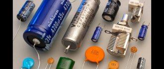
What is a capacitor
Condenser, or as people say - “conder”, is formed from the Latin “condensatus”, which means “compacted, condensed”. It is a passive radio element that has the property of retaining an electric charge on its plates, if, of course, it is charged with some kind of power source beforehand.
Roughly speaking, a capacitor can be thought of as a battery or accumulator of electrical energy. But the whole difference is that an accumulator or battery contains an EMF source, while a capacitor lacks this internal source.
What does a capacitor consist of?
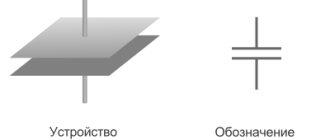
Any capacitor consists of two or more metal plates that do not touch each other. For a more complete understanding of how all this works in a capacitor, let's imagine a pancake.
spread it with condensed milk
and put the exact same pancake on top
The condition must be met: these two pancakes must not touch each other. That is, the top pancake should lie on the condensed milk and not touch the bottom pancake. Here, I think, everything is clear. Here is a typical “pancake capacitor” :-). This is how all capacitors are designed, only thin metal plates are used instead of pancakes, and various dielectrics are used instead of condensed milk. The dielectric can be air, paper, electrolyte, mica, ceramics, and so on. Wiring is connected to each metal plate - these are the leads of the capacitor.
Schematically it all looks something like this.
As you may have noticed, due to the dielectric, the capacitor cannot conduct current. But this applies only to direct current. The capacitor passes alternating current through itself without problems with a small resistance, the value of which depends on the frequency of the current and the capacitance of the capacitor itself.
Charge determination
You can determine whether the conductor is charged using a special measuring device. For example, this can be done using an indicator screwdriver. When discharged, the excess types of electrons having the left plate will be moved after some time along the wires to the right side of the plate, that is, they will be shifted to places where there are not enough of them.
You might be interested in this: Features of the power supply project
Note! When the number of electrons is the same, the discharge will stop and the conductive energy along with the resistance will disappear.
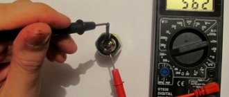
Using measuring equipment to determine capacitor charge
Where and what are they used for?
As already mentioned, it is difficult to find a circuit without capacitors. They are used to solve a variety of problems:
- To smooth out surges in network voltage. In this case, they are placed at the input of devices, in front of microcircuits that are demanding on power parameters.
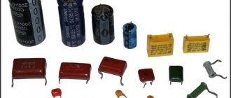
- To stabilize the output voltage of power supplies. In this case, you need to look for them before leaving. Electrolytic cylindrical capacitors are often seen
- Touch sensor (touch pads). In such devices, one of the “plates” of capacitors is a person. Or rather, his finger. Our body has a certain conductivity. This is what is used in touch sensors.
- To set the required rhythm of work. The charging time for capacitors of different capacities is different. In this case, the charge/discharge cycle of the capacitor remains constant. This is used in circuits where it is necessary to set a certain rhythm of work.
- Memory cells. The memory of computers, phones and other devices is a huge number of small capacitors. If it is charged, it is one, if it is discharged, it is zero.
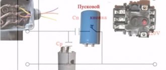
- There are starting capacitors that help “accelerate” the engine. They accumulate a charge, then release it sharply, creating the required “push” to accelerate the motor.
- In photo flashes. The principle is the same. First, the charge is accumulated, then released, but converted into light.
Capacitors are common and their applications are wide. But you need to know how to connect them correctly.
Processes of charging and discharging capacitors.
We've figured out the device, now let's figure out what happens if we connect a DC source to the capacitor. On circuit diagrams, a capacitor is designated as follows:
So, we have connected the capacitor plates to the poles of the DC source. What will happen?
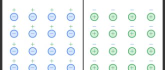
Free electrons from the first plate of the capacitor will rush to the positive pole of the source. Because of this, there will be a lack of negatively charged particles on the plate, and it will become positively charged. At the same time, electrons from the negative pole of the current source will move to the second plate of the capacitor. As a result, an excess of electrons will appear on it, and accordingly, the plate will become negatively charged. Thus, charges of different signs are formed on the plates of the capacitor (this is exactly the case we considered in the first part of the article), which leads to the appearance of an electric field that will create a certain potential difference between the plates of the capacitor. The charging process will continue until this potential difference becomes equal to the voltage of the current source. After this, the charging process will end and the movement of electrons along the circuit will stop.
When disconnected from the source, the capacitor can retain accumulated charges for a long time. Accordingly, a charged capacitor is a source of electrical energy, which means that it can release energy into an external circuit. Let's create a simple circuit by simply connecting the capacitor plates to each other:
In this case, a capacitor discharge current will begin to flow through the circuit, and electrons will begin to move from the negatively charged plate to the positive one. As a result, the voltage across the capacitor (the potential difference between the plates) will begin to decrease. This process will end at the moment when the charges of the capacitor plates become equal to each other, accordingly, the electric field between the plates disappears and current stops flowing through the circuit. This is how the capacitor discharges, as a result of which it releases all the accumulated energy into the external circuit.
It's better to check first
First, this element needs to be de-energized. It is clear that there is no need to deprive it of its power source. It is enough to turn off the electrical appliance and disconnect the plug from the socket. If you approach this issue radically, then for safety you can turn off all the circuit breakers at the switchboard that are responsible for supplying electricity to the room.
Now we need a special device - a multimeter - to find out whether the capacitor is charged.
- Select the mode for measuring DC voltage (direct current).
- We set the device knob to the maximum voltage measurement level.
- We connect the multimeter probes to the contacts of the electronic component. As a rule, two rods protrude from it. It is to them that you need to connect both probes of the detector. You need to press firmly enough so that digital readings appear on the device display. It makes no difference which probe goes to which contact. The resulting value will be the same in both cases.
We need to understand what voltage is at the terminals of the element. Depending on the indications, the discharge method is selected:
- If the reading is less than 10 volts, there is no need to discharge.
- If the display shows measurements between 10–99 volts, you can discharge it with a screwdriver.
- If values are 100 volts or higher, it is recommended to use a discharge device.
Important! Do not touch the terminals with bare hands - residual voltage may cause electric shock or burns.
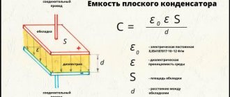
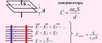
Capacity and energy of a capacitor.
The most important characteristic is the electrical capacitance of the capacitor. This is a physical quantity that is defined as the ratio of the charge of the capacitor q of one of the conductors to the potential difference between the conductors:
C = frac{q}{Deltavarphi} = frac{q}{U}
The capacitance of a capacitor is measured in Farads, but 1 F is quite large, so capacitance is most often measured in microfarads (µF), nanofarads (nF) and picofarads (pF). And since we have already derived the formula for calculating the voltage, let's express the voltage across the capacitor as follows:
It will be interesting➡ Who invented electricity? The history of the development of electricity - who discovered it and in what year
U = Ed = frac{qd}{varepsilon_0thinspacevarepsilon S}
Here we have d is the distance between the plates of the capacitor, and q is the charge of the capacitor. Let's substitute this formula into the expression for capacity:
C = frac{qvarepsilon_0thinspacevarepsilon S}{qd} = frac{varepsilon_0thinspacevarepsilon S}{d}
If we use air as a dielectric, then in all formulas we can substitute varepsilon = 1.
The following expressions are valid for the stored energy of a capacitor:
W = frac{CU^2}{2} = frac{qU}{2} = frac{q^2}{2C}
In addition to capacitance, capacitors are characterized by another parameter, namely the amount of voltage that its dielectric can withstand. When the voltage is too high, the dielectric's electrons are stripped from the atoms, and the dielectric begins to conduct current. This phenomenon is called capacitor breakdown, and as a result, the plates become short-circuited to each other. Actually, the characteristic that is often used when working with capacitors is not the breakdown voltage, but the operating voltage. This is a voltage value at which the capacitor can operate indefinitely for a long time, and breakdown will not occur.
So, today we looked at the basic properties of capacitors, their structure and characteristics! So this ends the article, and in the next one we will discuss various connection options and markings. Do not miss!
EXPERIMENT 2
Study of the time dependence of the amount of heat released at the load during capacitor discharge
- Carrying out actions similar to those described in experiment 1, charge the capacitor to a voltage corresponding to the total emf value. for your option.
- Press the "Stop" button and turn off the K key.
- Carry out a 5-second process of partial discharge of the capacitor through the connected lamps. To do this, press the “Start” button and the stopwatch start button simultaneously and after 5 seconds, press the “Stop” button to stop the process of discharging the capacitor.
- Record the ammeter readings in Table 4 and recharge the capacitor to the original voltage.
- Consistently increasing the duration of the capacitor discharge process by 5 s, perform these experiments until the discharge time corresponds to the complete disappearance of the charge on the capacitor. (The voltage across the capacitor and the discharge current through the lamps should be close to zero). Record the results of discharge current measurements in the appropriate cells of Table 4.
Table 4. Results of measurements and calculations
| Discharge time t, s | 5 | 10 | 15 | 20 | 5n | |
| Discharge current I after t s, A | ||||||
| Amount of heat Q per t s, J |
PROCESSING RESULTS:
- For each discharge time, calculate using formula (4) the amount of heat released by six lamps and write these values in the corresponding cells of the third row of Table 4. Helpful advice: to calculate Q, use MS Excel.
- Plot a graph of the dependence of the amount of heat released Q at a given time on the duration of the capacitor discharge process t.
- Compare the calculated amount of heat released by the time the capacitor is completely discharged with its theoretical value, equal to .
- Draw conclusions from the graph and answer and calculate measurement errors.
Distance between plates
The capacitance of a capacitor is inversely proportional to the distance between the plates. In order to explain the nature of the influence of this factor, it is necessary to recall the mechanics of the interaction of charges in space (electrostatics).
If the capacitor is not in an electrical circuit, then the charged particles located on its plates are influenced by two forces. The first is the repulsive force between like charges of neighboring particles on the same plate. The second is the force of attraction of opposite charges between particles located on opposite plates. It turns out that the closer the plates are to each other, the greater the total force of attraction between charges with the opposite sign, and the more charge can be placed on one plate.
DIY discharge device
Before measuring the capacity, check the condensers for breakdown or leakage, or if you need to replace a faulty element, you need to discharge it. It is especially important to make the correct discharge for high-voltage, high-capacity radio components. The accumulated energy can persist for a long time and improper dismantling or storage can pose a threat to life.
An inexpensive, easy-to-implement electronic device can be assembled to safely discharge high-voltage capacitors. It discharges quite efficiently and safely.
Let's look at its circuit diagram:
The voltage from the high-voltage capacitor is supplied to the quenching resistor R1 and then goes to a double-sided diode voltage limiter.
The diode limiter itself consists of two parallel chains of diodes D1-D3 and D4-D6. This is done in order to remove a voltage of about 2 volts from any diode in the circuit for the operation of LED indicators D7, D8. The incoming current to the LEDs is limited by resistor R2.
The LED starts the process of discharging the high-voltage capacitor to a safe voltage of about two volts.
The discharge process may take some time from 10 seconds. and more. The discharge time depends on the capacity of the connected condenser and what residual voltage remains in it.
As soon as the LED goes out, you can carry out the final discharge by short-circuiting the terminals of the radio component using a screwdriver.
The scheme is quite workable.
The entire board can be assembled independently and placed in a plastic case.
Time required to charge the capacitor
Under ideal conditions, when the voltage source is powerful, there is no obstruction to the flow of electricity, the capacitor is flawless, the charging time of the capacitor will be 0.
In practice, at each section of the circuit there is explicit (resistors) or implicit (wires, voltage source, etc.) resistance. In this case, the charging time of the capacitor will depend on the resistance in the entire circuit and its capacitance.
At the very beginning of the charge, there is a lot of free space on the plates of the drive, and the voltage is zero. The initial current at this moment is maximum. As the capacitor is filled with charged particles, their flux gradually decreases, and U grows more and more slowly. When there is no free space left on the plates, the current will stop, the voltage will become maximum and equal to that of the source.
The exponential increase in energy in a capacitor is shown in the figure. The formula itself for the dependence of the voltage increase on the charging time is as follows:
U=Uc*[1-e(-t/τ)]
where Uс is the electromotive force of the source, t is the charging time, τ is the time constant equal to R*C (R is resistance).
During time τ, the charging of the capacitor will reach (1 – 1/e)*100% ≈ 63% of U.
For 3τ – up to (1 – 1/e3)*100% ≈ 95% of U.
For 5τ – up to (1 – 1/e5)*100% ≈ 99% of U.
The time it takes to charge the capacitor exactly to the source voltage level lasts indefinitely.
From the above formula for calculating voltage, you can calculate the time it takes to charge the drive to certain indicators:
t = – ln (1 – U/Uc) * RC
Charging a capacitor from a source of constant EMF
The process of charging a capacitor, discussed in the previous section, by transferring charge from one plate to another, is of exclusively theoretical interest, as a method for calculating the energy of a capacitor. In reality, capacitors are charged by connecting them to an EMF source, for example, to a galvanic battery.
Let a capacitor of capacitance C be connected to a source whose emf is equal to ε
(Fig. 145). The complete electrical connection of the circuit (including the internal resistance of the source) will be denoted by R. When the key is closed, an electric current will flow in the circuit, due to which an electric charge will accumulate on the capacitor charges. According to Ohm's law, the sum of the voltages across the capacitor (~U_C = frac{q}{C}) and resistor (U_R = IR) is equal to the source emf (varepsilon = U_C + U_R), which leads to the equation
(~IR = varepsilon - frac{q}{C}) . (1)
In this equation, the capacitor charge and current depend on time. The rate of change of capacitor charge is by definition equal to the current in the circuit (~I = frac{Delta q}{Delta t}), which allows us to obtain an equation describing the change in capacitor charge over time
(~R frac{Delta q}{Delta t} = varepsilon - frac{q}{C}) . (2)
You can also obtain an equation that directly describes the change in current in a circuit over time. To do this, based on equation (1), we write the equations for small changes in input quantities
(~Delta varepsilon = Delta (IR) + Delta left (frac{q}{C} right )) .
Formally, this operation can be described as follows: equation (1) should be written for two moments of time t
and ( t + Δ t ), and then subtract the first from the second equation. Since the source emf is constant, its change is zero Δ ε = 0, the circuit resistance and capacitance of the capacitor are constant, so they can be taken out of the sign of the change Δ, so the resulting equation takes the form
(~R Delta I = - frac{1}{C} Delta q) .
Finally, we divide it by the period of time during which these changes occurred, as a result we obtain the desired equation (taking into account the relationship between the current strength and charge changes)
It will be interesting➡ Balast for fluorescent lamps
(~frac{Delta I}{Delta t} = -frac{1}{RC} I) . (3)
The mathematical meaning of this equation indicates that the rate of decrease in current is proportional to the strength of the current itself. To uniquely solve this equation, it is necessary to set the initial condition - the value of the current at the initial moment of time I
0 = I(0).
We became acquainted with equations of this type in the “mathematical digression”, so here we will analyze it briefly.
At the initial moment of time, when the charge of the capacitor is zero, the rate of charge increase (that is, the current strength) is maximum and equal to (~I_0 = Delta left (frac{Delta q}{Delta t} right )_0 = frac{varepsilon}{R} ).
Then, as the charge accumulates, the current strength will decrease, when the voltage on the capacitor becomes equal to the source emf, the capacitor charge reaches its maximum stationary value (~overline{q} = Cvarepsilon) and the current in the circuit stops.
Schematically, the time dependences of the capacitor charge and current in the circuit are shown in Fig. 146. To estimate the charging time of a capacitor, we can assume that the charge increases to a maximum value at a constant rate equal to the current strength at the initial time. In this case
(~tau = frac{overline{q}}{I_0} = RC) . (4)
A similar estimate of the disappearance of the current, obtained on the basis of equation (3), leads to the same result.
Strictly speaking, the charging time of the capacitor described by equation (2) is equal to infinity. This paradox can be eliminated if we take into account the discreteness of the electric charge.
In addition, the charge of a capacitor connected to the battery changes randomly over time and fluctuates, so the equation under consideration describes some average characteristics of the process.
However, the resulting estimate of the RC time is widely used in approximate calculations; it is often simply called the capacitor charging time
Let us now consider the transformations of various forms of energy in this process. It is clear that the cause of the current in the circuit and, as a consequence, the charging of the capacitor are external forces from the source.
At first glance, the energy balance includes a certain contradiction: if the source imparted a charge q to the capacitor
, then the external forces did the work A 0 = qε, and the energy of the capacitor became equal to (~W = frac{q2}{2C} = frac{q varepsilon}{2}), which is half the work done by the source.
The contradiction disappears if we take into account that during the charging process an electric current flows through the circuit, therefore a certain amount of heat is released at the resistor, that is, part of the source energy is converted into heat. Let's mentally divide the charging time into small intervals Δt
i (i = 1,2,3…). Let us rewrite equation (1) in the form
(~varepsilon = IR + frac{q}{C}) , (5)
and multiply it by the value of a small portion of charge transferred over a short period of time Δt
i, Δ qi = I iΔ ti . As a result we get
(~varepsilon Delta q_i = I_i R Delta q_i + frac{q_i}{C} Delta q_i) . (6)
Here we denote q
i is the charge of the capacitor before transferring the portion of charge under consideration. Each member of the resulting equation has a clear physical meaning: [~varepsilon Delta q_i = delta A] - the work of external forces to move a portion of the charge Δ qi; [~frac{q_i}{C} Delta q_i = Delta W_C] - an increase in the energy of the capacitor with increasing its charge by Δ qi;[~I_i R Delta q_i = I2_i R Delta t_i = delta Q] - the amount of heat released on the resistor when a portion of charge Δ q i flows.
Thus, the law of conservation of energy, expressed by the balance equation (6) for a short period of time turns out to be fulfilled, therefore, it will be fulfilled for the entire charging process.
Let's sum up expression (5) over all charging time intervals, resulting in: [~sum_i varepsilon Delta q_i = varepsilon overline{q} = A] - the total work of external forces to transfer an electric charge equal to the stationary charge of the capacitor;[~sum_i frac {q_i}{C} Delta q_i = frac{overline{q2}}{2C} = frac{varepsilon overline{q}}{2} = frac{C varepsilon2}{2}] is the energy of the charged capacitor;
finally, (~sum_i I_i R Delta q_i = sum_i I2_i R Delta t_i) - the amount of heat released by the resistor.
Taking into account equation (3) and the formulas from the “mathematical digression”, the last sum can be expressed as
(~Q = R sum_i I2_i Delta t_i = R frac{1}{2} I2_0 tau = R frac{1}{2} left ( frac{varepsilon}{R} right )2 RC = frac{C varepsilon2}{2 }) . (6)
This amount can be calculated graphically. Formula (1) specifies the dependence of the voltage across the resistor (U_R = IR) on the charge of the capacitor. This dependence is linear; its graph (Fig. 147) is a straight line segment.
In a short period of time, a small charge Δq will flow through the resistor
i, in this case an amount of heat will be released (~delta Q_i = I_i R Delta q_i), which is numerically equal to the area of the narrow strip highlighted in the figure.
The total amount of heat released during the passage of the entire charge is numerically equal to the area of the triangle under the graph of the dependence U
R(q), that is
EXPERIMENT 1
Determining the capacitance of a capacitor using the discharge method
1.Assemble a closed electrical circuit on the working part of the screen, shown below in Fig. 2. To do this, first click on the emf button located on the right side of the experiment window. Move the mouse marker to the working part of the screen where the dots are located, and click the mouse marker in the form of an extended index finger in the place where the current source should be located. Move the mouse marker to the slider of the e.m.f. regulator that appears, click on the left mouse button, holding it down, change the e.m.f. value. and set 10 V. Similarly, connect 4 other current sources to the circuit. Total value of e.m.f. The battery must match the value shown in Table 1 for your option.
In the same way, further place on the working part of the screen 7 lamps L1-L7 (button), Key K (button), voltmeter (button), ammeter (button), capacitor (button). Connect all elements of the electrical circuit according to the diagram in Fig. 1 using mounting wires (button ).
2. Click the “Start” button. Lamp L7 should light up, and the inscription on the button should change to “Stop”. Use the mouse cursor to close key K.
3. After establishing a stationary current in the circuit (lamps L5 and L6 should go out and lamps L1-L4 should light up), write down the readings of electrical measuring instruments in Table 2.
4. Click on the “Stop” button and use the mouse cursor to open key K.
5. With two short mouse clicks on the “Start” button, start and stop the process of discharging the capacitor. The ammeter readings will correspond to the initial discharge current of the capacitor I0. Record this value in Table 3.
6. Close the key again, charge the capacitor and repeat. 5, 6 4 more times.
7. For each experiment, calculate It = I0/2.7 - the current strength that should be in the capacitor discharge circuit after the relaxation time t and write these values in Table 3.
8. With the key open, press the “Start” button to start the process of discharging the capacitor and at the same time turn on the stopwatch.
9. Carefully observe the change in ammeter readings as the capacitor discharges. Stop the stopwatch and press the Stop button synchronously when the ammeter reading is equal to or close to It. Record this time t1 in Table 3.
10. Perform experiments pp. 8, 9 4 more times.
Table 1. Total emf value. current sources
| Option | 1 | 2 | 3 | 4 | 5 | 6 | 7 | 8 |
| E.m.f., V | 50 | 49 | 48 | 47 | 46 | 45 | 44 | 43 |
Table 2. Determination of lamp resistance.
| No. | I, A | U, V | R, Ohm |
Experience number | 1 | 2 | 3 | 4 | 5 | Average meaning |
| I0, A | ||||||
| It, A | ||||||
| t, s | ||||||
| C, F |
Table 3. Results of measurements and calculations.
PROCESSING RESULTS:
1. Using Ohm’s law for the circuit section L1-L4: and the measurement results given in Table 2, determine the resistance of one lamp.
2. Using the formula (when a capacitor is discharged, a quasi-stationary current flows through 6 series-connected lamps), determine the capacitance of the capacitor and write these values in Table 3.
3. Calculate measurement errors and formulate conclusions based on the results of the work done.
Series connection of capacitors
If the connection of capacitors in a battery is made in the form of a chain and the plates of only the first and last capacitors are directly connected to the connection points in the circuit, then such a connection of capacitors is called serial. When connected in series, all capacitors are charged with the same amount of electricity, since only the outer plates are charged directly from the current source, and the remaining plates are charged through influence. In this case, the charge of the plate will be equal in magnitude and opposite in sign to the charge of plate 1, the charge of plate 3 will be equal in magnitude and opposite in sign to the charge of plate 2, etc.
The voltages on different capacitors will, generally speaking, be different, since charging capacitors of different capacities with the same amount of electricity always requires different voltages.
Types of capacitor connections. The smaller the capacitance of the capacitor, the greater the voltage required in order to charge this capacitor with the required amount of electricity, and vice versa.
Thus, when charging a group of capacitors connected in series, the voltages on small capacitors will be greater, and on large capacitors - less.
It will be interesting➡ Reactance
Similar to the previous case, we can consider the entire group of capacitors connected in series as one equivalent capacitor, between the plates of which there is a voltage equal to the sum of the voltages on all capacitors of the group, and the charge of which is equal to the charge of any of the capacitors of the group. Let's take the smallest capacitor in the group. There should be the greatest tension on it. But the voltage across this capacitor is only a fraction of the total voltage that exists across the entire group of capacitors. The voltage across the entire group is greater than the voltage across the capacitor with the smallest capacitance. And from here it directly follows that the total capacitance of a group of capacitors connected in series is less than the capacitance of the smallest capacitor in the group.
A series connection of capacitors is the connection of two or more capacitors in the form of a circuit in which each individual capacitor is connected to another individual capacitor at only one point. The current (iC) charging a series capacitor circuit will be the same for all capacitors because it has only one possible path.
Due to the fact that the same current flows through all capacitors connected in series, the amount of accumulated electrical charge for each capacitor will be the same, regardless of its capacitance. This happens because the electrical charge accumulated on the plate of any capacitor must come from the plate of the adjacent capacitor. Thus, capacitors connected in series have the same electrical charge.
Worth reading: everything about electrolytic capacitors.
The right plate of the first capacitor C1 is connected to the left of the second capacitor C2, whose right plate is connected to the left of the third capacitor C3. This means that in DC mode, capacitor C2 is electrically isolated from the general circuit. As a result, the effective area of the plates is reduced to the area of the plates of the smallest capacitor. This is explained by the fact that as soon as the plates of the smallest area are filled with electric charge, this capacitor will stop passing current. As a result, the current will stop in the entire circuit, and the charging process of the remaining capacitors will also stop. With a series connection, the total distance between the plates increases to the sum of the distances between the plates of all capacitors.
Thus, the series circuit forms one large capacitor with the area of the plates of the element with the smallest capacitance, and the distance between the plates equal to the sum of all distances in the circuit. Each individual capacitor in a series circuit experiences a different voltage drop. Since capacitance is inversely proportional to voltage (C = Q/V), the smaller the capacitance of the capacitor, the greater the voltage will drop across it. Let us apply Kirchhoff's law to the voltage in a series circuit of three capacitors.
The capacitance of a capacitor is directly proportional to its charge and inversely proportional to its voltage - C = Q/V. As mentioned above, capacitors connected in series have the same electrical charge - Qtot = Q1 = Q2 = Q3. From this equation you can easily derive the formula for the total capacitance for any particular case of a series connection.
If a circuit has both a serial and parallel connection, then such a circuit is called mixed or series-parallel. However, a mixed connection can be either serial or parallel.
Types of capacitor connections.
Purpose
Capacitor for subwoofer
First, let’s find out what the purpose of this element of the speaker system is. Below is detailed information:
- Let us note right away that it is capable of significantly improving the parameters of the amplifier used, and therefore is a very important chain in the entire car audio system.
Note. It all comes down to the fact that modern low-frequency or bass drivers consume significant current at times and, thus, even the most powerful battery is not able to provide them with constant power.
- Why does the subwoofer consume so much current, maybe the wires laid to it are too thick? It turns out that this is not the case at all. No matter how thick the wires and cables are, they undoubtedly have resistance, which at a certain moment causes current surges and a drop in its power;
- Experts advise not to forget about the work of additional consumers, which also does not have a positive effect on the functioning of the amplifier. We are talking, for example, about an air conditioner that operates in the hot season and can consume up to 30 percent of the generator’s energy. All this leads to the fact that when playing powerful bass, unwanted sound distortion occurs, explained by the inability of the battery to provide the desired tempo;
- In these cases, the best option that works 100% is a good, high-quality woofer capacitor. This element is nothing more than a high-capacity electrolytic.
For subwoofer capacitor
Note. The capacitor must be connected in parallel to the amplifier's power supply circuit.
- The right capacitor for a subwoofer has low internal resistance. This is necessary so that the pulse current flows to the amplifier instantly. In this way, all possible failures are completely eliminated or minimized to the extreme.
Interesting. It is noteworthy that the capacitor is charged at the same champion speed and, like a pioneer, is always ready to again give out the necessary portion for the bass player.
Laws of series and parallel connection of conductors
For a detailed understanding in practice of both types of connections, we present formulas explaining the laws of these types of connections. Power calculations for parallel and series connections are different.
In a series circuit, there is the same current in all conductors:
I = I1 = I2.
According to Ohm's law, these types of conductor connections are explained differently in different cases. So, in the case of a series circuit, the voltages are equal to each other:
U1 = IR1, U2 = IR2.
In addition, the total voltage is equal to the sum of the voltages of the individual conductors:
U = U1 + U2 = I(R1 + R2) = IR.
The total resistance of an electrical circuit is calculated as the sum of the active resistances of all conductors, regardless of their number.
In the case of a parallel circuit, the total voltage of the circuit is similar to the voltage of the individual elements:
U1 = U2 = U.
And the total strength of the electric current is calculated as the sum of the currents that exist in all conductors located in parallel:
I = I1 + I2.
To ensure maximum efficiency of electrical networks, it is necessary to understand the essence of both types of connections and apply them expediently, using the laws and calculating the rationality of practical implementation.
How to connect capacitors correctly?
Many novice electronics enthusiasts in the process of assembling a homemade device have a question: “How to connect capacitors correctly?”
It would seem why this is necessary, because if the circuit diagram indicates that a 47 microfarad capacitor should be installed in a given place in the circuit, then we take it and install it. But, you must admit that in the workshop of even an avid electronics engineer there may not be a capacitor with the required rating!
A similar situation may arise when repairing any device. For example, you need an electrolytic capacitor with a capacity of 1000 microfarads, but you only have two or three at hand with a capacity of 470 microfarads. Set 470 microfarads instead of the required 1000? No, this is not always acceptable. So what should we do? Go to the radio market several tens of kilometers away and buy the missing part?
How to get out of this situation? You can connect several capacitors and as a result get the capacitance we need. In electronics, there are two ways to connect capacitors: parallel and series.
In reality it looks like this:
Parallel connection Circuit diagram of parallel connection Serial connection Circuit diagram of series connection
It is also possible to combine parallel and serial connections. But in practice you are unlikely to need this.