One of the important parameters taken into account in electrical circuits is electrical capacitance - the ability of conductors to accumulate charges. The concept of capacitance is used both for a solitary conductor and for a system consisting of two or more conductors. In particular, capacitors consisting of two metal plates separated by a dielectric or electrolyte have capacitance.
Batteries are widely used to accumulate charges and are used as direct current sources to power various devices. The quantitative characteristic that determines the operating time of a battery is its electrical capacity.
Definition
If a dielectric, for example, an ebonite stick, is electrified by friction, then the electric charges will concentrate at the points of contact with the electrifying material. At the same time, the other end of the stick can be saturated with charges of opposite sign and such electrification will be maintained.
Conductors exposed to an electric field behave completely differently. Charges are distributed over their surface, forming a certain electrical potential. If the surface is smooth, like a stick, then the charges will be distributed evenly. Under the influence of an external electric field, electrons are distributed in a conductor in such a way that a balance of mutual compensation of negative and positive charges is maintained inside it.
An external electric field attracts electrons to the surface of the conductor, compensating for the positive charges of the ions. Electrostatic induction occurs in relation to a conductor, and the charges on its surface are called induced. In this case, at the ends of the conductor the charge density will be slightly higher.
On a metal ball, charges are distributed evenly over the entire surface. The presence of a cavity of any configuration has absolutely no effect on the distribution process.
However, if the conductor is removed from the field, its charges will be redistributed in such a way that it will again become electrically neutral.
Figure 1 shows a diagram of a charged dielectric with different polarities and a conductor removed from the electrostatic field. Due to the fact that the dielectric retains the resulting charges, the isolated conductor has regained its neutrality.
Rice. 1. Charge distribution
An interesting phenomenon is observed with two conductors separated by a dielectric. If one of them is given a positive charge and the other a negative charge, then after the source of electrification is removed, the charges on the surface of the conductors will remain. Conductors charged in this way have a potential difference.
The charges accumulated on the dielectric balance the internal interactions in each of the conductors, preventing them from being discharged. The amount of charge depends on the surface area of the parallel conductors and on the properties of the dielectric located between them.
The property of storing accumulated charge is called electrical capacitance. More precisely, it is a characteristic of a conductor, a physical quantity that determines the measure of its ability to accumulate an electric charge.
The accumulated electricity can be removed from the conductors by short-circuiting them or through a load. In order to increase the capacity, in practice parallel plates or long strips of thin foil separated by a dielectric are used. The strips are rolled into a tight cylinder to reduce volume. Such structures are called capacitors.
Figure 2 shows the circuit of a simple capacitor with flat plates.
Rice. 2. Circuit of a simple capacitor
There are other types of capacitors:
- variables;
- electrolytic;
- oxide;
- paper;
- combined and others.
An important characteristic of a capacitor, like other storage systems, is its electrical capacity.
How to measure capacitance
There are a number of ways to measure capacitance of a capacitor using instruments and various techniques. The article describes the use of a multimeter, oscilloscope, tester and bridge meters.
Multimeter
In the beginning, before you start measuring the capacitance of the capacitor, it must be discharged until the current completely disappears.
As an example: do this by shorting the terminals with a screwdriver.
If you neglect this nuance, the multimeter may break.
You can measure capacitance using a multimeter as follows: activate the “Cx” mode and set the measurement limit to 2000 pF, if any. On a standard device it is equal to 20 µF; Install the capacitor into the appropriate sockets in the multimeter or use probes to connect the capacitor. The capacitance value will be displayed on the device screen.
Oscilloscope
To measure, you will need, in addition to an oscilloscope, to assemble a circuit from the capacitor being tested, a resistor and a sinusoidal oscillation generator.
The connection points of the oscilloscope to the circuit are located before the resistor and after the capacitor.
The oscillator frequency changes until sinusoidal curves of equal amplitude are obtained on the oscilloscope screen. This is done for measurement accuracy. Imagine how to calculate the capacitance of a capacitor using amplitude voltage values? To do this, you need to use the formula UR/UC*2πfR and substitute the measured values into it. With its help, the leakage current of the capacitor is also calculated indirectly - by reducing the voltage across a previously known resistance. The oscilloscope is capable of calculating the capacitance of capacitors from 20 pF to 200 mkF.
A tester that does not have a direct function
To find an option for determining capacity using a tester without a capacity measurement function, you should pay attention to the formula for the instantaneous value of the current during charging or discharging i = C dU/dt.
The point here is that in addition to the tester and stopwatch, you should assemble a circuit with a power source,
a capacitor and a resistor with high resistance to increase the duration of the charging or discharging process. After taking all the readings from the tester and stopwatch, you can fairly approximately calculate and find out the capacity. Knowing how to determine the capacitance of a capacitor with modern instruments, it will not be difficult to understand the device from the times of the USSR. The display does not display numbers, but rather the deviation of the arrow, which is important to monitor closely. Capacitance measurements are carried out only on a discharged capacitor. Lead the probes to the contacts of the capacitor; if it is working, the arrow will initially deflect, after which it will take its original position as it charges. The speed of movement of the arrow depends on the volume of the container. If the tester's needle does not budge, or this value is minimal, or deviates and hangs in one position, this is an indicator of a faulty capacitor.
Bridge meters
The capacitance of the capacitor is measured by comparison with the reference capacitance. Why is a bridge circuit performed, where one arm works with a reference electrical device, the other with the one being tested. Bridge readings can be implemented on digital media.
Formulas
Figure 3 clearly shows the formulas for determining capacity, including for a sphere.
Rice. 3. Electrical capacity of the conductor
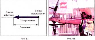
In relation to a capacitor, to determine its capacity, use the formula: C = q/U . That is, this value is directly proportional to the charge of one of the plates and inversely proportional to the potential difference between the plates (see Fig. 4).
Capacitor capacity
Read about other ways to determine the capacitance of a capacitor in our article:
Capacitance unit
Capacitor capacity: formula
Capacitance indicators are usually measured in farads. In Russia, in calculations, it is customary to abbreviate the name of the unit to the capital letter F; in international documents it is called the Latin letter F. It is named after the English physicist Michael Faraday. The value of 1 F is taken to be such a capacitance at which, when transporting a one-coulomb charge from one plate to another (or from one point to another), the voltage between them will change by one volt.
Unit of measurement of electrical capacity in other systems
The use of the farad to describe capacitance was introduced into the SI system in 1960. In the Gaussian system, a statfarad is used for this. It is customary to abbreviate such a unit in writing as statf. 1 statF is approximately equal to 1.11 picofarads and describes the capacitance of a sphere having a radius of 1 centimeter and placed in a vacuum environment. You can convert the values of a particular quantity in non-systemic units into those accepted in SI using special calculators.
Solitary conductor and its capacity
A conductor is called solitary, the influence on which of other circuit elements can be neglected. It is assumed that all other conductors are infinitely distant from it, and as is known, the potential of a point infinitely distant in space is equal to 0.
The electrical capacitance C of an isolated conductor is defined as the amount of electricity q that is required to increase the electrical potential by 1 V: C = q/ ϕ. The parameter does not depend on the material from which the conductor is made.
Maximum operating voltage on capacitor
The voltage supplied to the capacitor should not exceed the maximum, as dielectric breakdown may occur and the element may fail.
To analyze the operation of a capacitor in an alternating current circuit, the amplitude voltage value should be taken as a criterion for comparison with the maximum possible value.
This means that if some maximum voltage DC WV is indicated on it, then in reality when connected to the network it should be 1.4 less.
Fixed and variable capacitors
The era of electricity storage began with air capacitors. Thanks to the large-area parallel-plate capacitor, physicists were able to understand how mutual capacitance is controlled by the areas of the plates, which allowed them to create capacitors with variable capacitance (see Figure 5).
Rice. 5. Variable capacitor
The idea of changing the capacitance was to change the surface area, which is located opposite the other plate, by rotating the flat plate. If the plates were located exactly opposite each other, then the field strength between them was maximum. When one of the plates was shifted by a certain angle, the voltage decreased, which led to a change in capacitance. Thus, it was possible to smoothly control the storage capacity of the capacitor.
Parts with variable capacitance were used in the first radio receivers to search for the frequency of the desired station. This principle is still used today in various analog electrical circuits.
Electrolytic capacitors have become very popular. As one of the plates, they use an electrolyte with high dielectric constants. Due to the dielectric properties of electrolytes, such capacitors have large capacities.
Their main advantages of an electrolytic capacitor:
- high capacity with low volume;
- Application in circuits with direct current.
Flaws:
- polarity must be observed;
- limited service life;
- sensitivity to increased stress.
Flat-plate capacitors that use ceramics as a dielectric material have high electrical strength. They are used in alternating current circuits and can withstand high voltages.
Today, industry supplies the market with a variety of capacitors of various types, with high dielectric permeability values.
Capacitors of various types
Capacitor
In order to experimentally determine the electrical capacity of a conductor, as well as its potential, it is necessary to create conditions that exclude the influence of all surrounding bodies, which, influencing the body, change its potential and electrical capacity.
This statement can be verified by experience. Let's attach a metal ball to the electrometer rod and give it a certain charge. The instrument needle will deviate from the equilibrium position and show a certain potential value relative to the ground.
Let's bring a metal plate connected to the ground by a conductor to the ball (Fig. 1.32).
Fig. 132. A grounded metal plate affects the electrical capacity of the ball
The electrometer needle reading will decrease. Since the charge of the ball did not change in the experiment, the decrease in potential indicates an increase in the electrical capacity of the ball. A change in the potential and, accordingly, the electrical capacity of the ball will also be observed if the distance between the ball and the plate changes.
Thus, when determining the electrical capacity of a body, it is also necessary to take into account the presence of surrounding bodies. Since this is difficult to do in practice, a system of two or more conductors of arbitrary shape separated by a dielectric is used. In this case, the electrical properties of such a system of conductors and dielectric do not depend on the surrounding bodies. Such a system is called a capacitor. The simplest one to study and calculate is a capacitor made of two metal plates separated by a dielectric.
The electrical capacity of a capacitor, in contrast to a separate body, is determined by the potential difference between the plates:
where Q is the charge of one plate; (φl- φ2) and ∆φ is the potential difference between the plates.
The word capacitor means storage. In electricity it is understood as a “store of electrical charges”.
Example:
What electrical capacity does a capacitor have if a charge of 50 nC accumulates on its plates at a potential difference of 2.5 kV?
| Given: Q = 50 nC, Aφ = 2.5 kV. | Solution We use the formula for the capacitance of the capacitor: |
| WITH-? |
Let's substitute the values of physical quantities:
Answer: the electrical capacity of this capacitor is 20 pF.
The first capacitor was created in 1745 by the Dutch scientist Pieter van Musschenbroek, a professor at Leiden University. While conducting experiments on the electrification of various bodies, he lowered the conductor from the conductor of an electric machine into a glass carafe with water (Fig. 1.33).
| Pieter van Musschenbroek (1692-1781) - Dutch physicist; works are devoted to electricity, heat, optics; invented the first capacitor, the Leyden jar, and conducted experiments with it. |
Fig. 133. From the history of the discovery of the simplest Leyden jar capacitor
Accidentally touching this conductor with his finger, the scientist felt a strong electric shock. Subsequently, the liquid was replaced with metal conductors mounted on the inner and outer surfaces of the can. This capacitor was called a Leyden jar. In this original form, it was used in laboratories for more than 200 years.
More advanced capacitors are used in modern electrical engineering and radio electronics. They can be found in voltage converters (adapters) that supply electronic devices with direct electric current, in radio receivers and radio transmitters as components of oscillatory circuits. They are used in almost all functional units of electronic equipment. In photoflashes, capacitors store the large charges needed to operate the flash.
In electrical engineering, capacitors provide the necessary operating mode for electric motors, automatic and relay devices, power lines, etc.
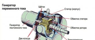
In many wide-range radio receivers, variable capacitors (Fig. 1.34) allow you to smoothly change the natural frequency of the oscillating circuit while searching for a transmission of a specific radio station.
Rice. 134. Variable capacitor with air dielectric
Varicapacitors are very common, the electrical capacity of which can be changed electrically. Structurally, they are very similar to semiconductor diodes.
Capacitors can be flat, tubular, or disk. They use waxed paper, mica, air, plastics, and ceramics as dielectrics (Fig. 1.35).
Rice. 1.35. Various types of capacitors
Artificially created dielectric materials make it possible to create capacitors of large capacities with small sizes.
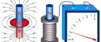
Batteries and electrical capacity
Large-capacity electrical storage devices (batteries) consist of positive and negative plates immersed in an electrolyte. During charging, some of the electrolyte atoms break up into ions, which settle on the plate. A potential difference is formed between the plates, which causes an EMF to occur when a load is connected.
In order to increase the voltage, the batteries are connected in series into batteries. The potential difference of one section is about 2 V. To obtain a 6 V battery, it is necessary to create a battery of three sections, and for 12 V, a battery of 6 sections.
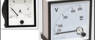
To characterize accumulators (batteries), the following parameters are used:
- containers;
- rated voltage;
- maximum discharge current.
The unit of battery capacity is ampere-hour (A*h) or its multiples milliamp-hours (mA*h). The battery capacity depends on the area of the plates. You can increase the capacity by connecting several sections in parallel, but this method is almost never used, since it is easier and more reliable to create a battery with large plates.
conclusions
- The electrical capacity of a battery is the most important indicator of the amount of electrical energy and the duration of its operation, expressed in numerical values. It can be determined, calculated, increased using various methods.
- Battery capacity (volume) may be different for both primary and secondary sources, but the latter can be recharged using chargers (chargers).
- Battery capacity depends on the type of cell, chemical reaction, external conditions, load current, shelf life and method of operation. If you violate the rules of use, you can quickly damage the battery, and with the right approach, its use time can be significantly extended.
- Batteries or accumulators manufactured by well-known manufacturers, as a rule, have proven themselves well in the consumer market, in that they guarantee the declared technical characteristics and high-quality, uninterrupted service in devices for a long time.
Marking of capacitors depending on capacity
When purchasing elements that correspond to the calculated data for a particular circuit, the user needs to be able to decipher the symbols on the device cases, informing how much capacity they are capable of accumulating. Different manufacturers have adopted different marking systems for radio components.
Encoding of small devices
On the housings of Soviet radio components, it was customary to designate picofarads as an integer (for example, 25). If on such a part the parameter is indicated by a number containing a decimal fraction, microfarads are implied. It was not customary to write the letter designations themselves (pF, μF and the like) on the housings.
Important! As for Russian products, nanofarads and microfarads are indicated by traditional abbreviations in which the letter F is reduced (it turns out “n” and “mk”, respectively). The capacity, calculated in picofarads, is indicated only by number, as with Soviet parts.
When a Latin prefix indicating a multiple of one is placed before a number, the latter must be counted as hundredths. For example, n45 means 0.45 nanofarads. When the prefix is in the middle of a number, there should be a comma in its place: 4u3 – 4.3 microfarads. A three-digit picofarad encoding is also used: when the last digit is not more than 6, in order to obtain a capacitive value, the first two digits must be assigned the number of zeros corresponding to this digit (340 - 34 picofarads, 342 - 3400). The numbers 7, 8 and 9 correspond to multiplications of a two-digit number by 0.001, 0.01 and 0.1, respectively.
Colored stripes are also used to designate product denominations. The indication of the capacitive parameter is regulated by the EIA standard.
Encoding of large devices
For large components, for example electrolytic ones made of aluminum, parameter data, including capacitance indicator, is indicated on the surface of the housing. Typically, the capacitance of such parts is expressed in microfarads. The letters M or MFD symbolize this particular unit. The three-digit abbreviation can also be indicated in lowercase letters - mfd.
Marking of large parts
Multiples of capacity units
Current unit
In most cases in electrical engineering, parts with small capacitance values are operated. Sometimes you will see designations such as 10uf capacitor. An inexperienced person may not immediately understand what the abbreviation uf means. It should be understood that the most common units in the description of capacitive elements are the following units: picofarad (or pF, it is equal to 10-12 F), nanofarad (nF, 10-9 F) and microfarad (μF, 10-6 F). Specifying the capacitance of a capacitor in uf means microfarads. It is advisable to purchase a table for converting measurement units of different scales to each other.
Multiple units are not used that often in practice. For some ionistor parts with a binary electrical layer, the capacitance indicator can be measured in kilofarads (kF, 1000 F). The value of standard capacitor elements usually does not exceed hundreds of farads.
Ionistor with a nominal value of 1 farad
Examination
As noted earlier, the capacity of the device is marked on its body. You can check the rated value and the available capacity of the device using a tester with the “CX” mode. For example, the popular models M890D, AM-1083, DT9205A, UT139C, and others are suitable for this. Next you will need:
- Unsolder and discharge the device. Discharge is carried out with a strictly insulated metal object.
- Insert the legs of the capacitor into the grooves “CX”, observing the polarity.
- The device will display the measurement result on the display. It will need to be compared with the one indicated in the markings on its body. If the values differ greatly from each other, this indicates that the element is faulty and requires replacement.
If the multimeter shows the presence of infinite capacity, then this indicates a short circuit inside the device body and it is also considered faulty and requires replacement. In addition, the malfunction can always be determined visually by cracks or swelling of the housing.