Regulatory documents and rules
The requirements for installing an electrical panel are specified in GOST 51321.1-2007.
The panel is a switchgear operating under voltage up to 1 kW. Its features are discussed in Chap. 4.1. 7th edition of the PUE. The requirements for the ASU in a residential multi-storey building are specified in GOST 51732-2001, and for switchboards - in GOST R 51628-2000. Since the apartment electrical panel is a low-voltage switchgear and control device, you need to refer to GOST 51321.1-2007.
Basic requirements and installation rules
GOSTs and PUE indicate the correct way to connect the panel.
The standards note several points:
- the presence of a complete circuit with the rating of the circuit breaker, the type and cross-section of the cable, installed and one-time power, protection parameters of the housing shell;
- installation of modules equipped with a nameplate inside or outside is permitted;
- mandatory affixing of the “Caution Voltage” sign in the form regulated by GOST R 12.4.026;
- selection of cable cross-section for laying inside according to the rating of the circuit breakers;
- selection of wire insulation capable of withstanding an alternating current voltage of at least 660 V;
- protection of bolted connections from vibrations and short circuits with disc springs, controllers, spring washers, tips;
- assembly of neutral conductors on N and RE buses;
- connecting the REN wire to the RE panel;
- use of terminals to protect input and output wires;
- performing work using screwdrivers with slots for screw slots, tools with insulated handles;
- cable marking with colored PVC tubes - blue/light blue (working zero), yellow-green (protection zero), red/brown (phase);
- marking of N and RE bus contacts according to the serial numbers of protective circuit breakers;
- connection of one conductor per bus terminal N or RE;
- designation of outgoing cables with round (line voltage from 1000 V), square (voltage up to 1000 V), triangular (control) tags.
Buses N and RE, separated in the power cable, cannot be combined.
Which case is more reliable - metal or plastic?
Metal distribution panel in a wooden house
The apartment panel is available in metal and plastic casings. The choice of material depends on the project, design specifications and financial capabilities of the user.
The metal electrical panel has a number of features:
- reliable landing on protective zero;
- high anti-vandal characteristics;
- good fire resistance;
- installed on the street or in the entrance;
- moisture resistance class IP31 – IP54.
The disadvantage of a metal case is the need for grounding. The third wire will need to be brought out from the main power supply panel of the apartment.
Plastic electrical panel near the door in the hallway
The plastic case has the following characteristics:
- suitable for interior design;
- can be built into a special niche;
- resistance to wet environments;
- beautiful transparent or tinted door;
- excellent dust resistance.
If the insulation is poor, there is a risk that the plastic will ignite and cause a fire. In this case, it is better to purchase a box made of textolite.
Regardless of the housing material, you can choose a shield for installation in an apartment for 12-72 modules.
How to connect the Shchur
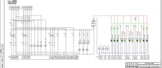
You can install and turn on the device yourself, but this requires a project, for example, a single-line diagram of a distribution board (for example, RShch-16). The device passport includes a diagram according to which the device must be put into operation, but before installing it, you need to study the requirements of the PUE for the existing network.
Photo - single line diagram
This scheme is developed individually for each enterprise or residential building. It can be ordered from special design bureaus. With the existing project, in the future it will be easier not only to connect the device, but also to assemble the necessary circuit.
Electrical panel elements
The apartment panel consists of the following components:
- Circuit breaker. A two-row device is placed at the input and can de-energize the neutral and phase wires.
- RCD. It is a differentiated type relay. Necessary for quickly de-energizing the line when a voltage leak occurs.
- Additional auto switches that control the circuit with powerful appliances - electric stove, washing machine, water heater, air conditioner.
- Zero and ground buses. Copper strips with a dielectric base ensure the safety of the grounding contact and the working neutral.
- Frame. It contains all the nodes. It can be metal or plastic. Depending on the installation method, a distinction is made between wall-mounted and built-in models.
- DIN rail. A metal plate fixed to the body. Automatic machines are mounted to it with special fasteners.
- Connecting cables with a cross-section corresponding to the power rating of the equipment.
The outer box should not allow current to pass through, so it is better to buy models made of heat-resistant plastic or metal with a polymer coating.
What should be in the electrical panel
In a private house, the electric meter is installed on a pole.
The layout of the distribution board in an apartment or private house comes in several options. The main difference is the presence of a counter and a machine at the input. In private houses, meters are placed on a pole, and machines are placed on the wall. The meter can also be located inside the house, and then a shield is required.
In multi-apartment buildings, electrical boxes are installed on the staircase. In this case, a cabinet is required for RCDs and automatic machines. Installation inside an apartment is also allowed, but this requires a compact and roomy product.
Nuances of choosing modular equipment for an electrical panel
Electrical resistance of PUGV wires
Before installing an electrical panel in the apartment, you will need to make a diagram of it and coordinate it with the energy sales company. The drawing indicates each module and its purpose. When selecting devices, you need to consider the following points:
- Use of modules from the same manufacturer and series. Depending on the manufacturer, the width of the modules varies by several millimeters. The difference leads to inconsistency of parts.
- The cross-section of the PuGV installation wire is selected to match the cross-section of the input cable. Optimally – from 4 to 6 mm2.
- To mark zero, ground and phase, you will need a thermal tube of white, black, red (phase) and black (working zero) colors.
- Bus combs with one to three strips will provide connection of modular devices. The combs will also need end caps.
- Each group RCD will need a separate zero bus or cross-modules with good insulation.
- A DIN rail stop will prevent a number of modules from spreading to the sides.
- Plugs are used to close the formed cavities in the shield.
To secure the wires inside the shield, you should buy plastic clamps.
Stage four: power supply to the top row of automation
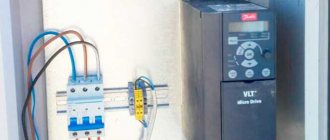
First of all, I connected the input machine and the UZM. For this, 2 pieces of wire with a cross section of 6 mm2 were used. As expected by color marking, the blue conductor was used as a neutral conductor, and the black conductor as a phase conductor. The ends, stripped using a stripper, were crimped with a crimper.
Supplying power from the input circuit breaker to the UZM
Initially, it seemed to me that it would be better to make the wire sections a little longer, but when the installation began, it became clear that this would look sloppy. As a result, a small reserve remained, but it was insignificant.
Next, a similar connection was made of residual current devices connected to each other using buses and a residual current circuit breaker. And here all the advantages of the absence of jumpers manifest themselves. There is more than enough free space left in the box. To an uninitiated person it may seem that RCDs and RCBOs are not connected to the network at all.
The top row of automation is assembled - testing can be carried out
After performing these operations, I decided to check the functionality of the top row of automation. For this, a wire with a plug was used (in the photo above you can see that it is connected to the input machine).
I will take the liberty of giving advice on testing. When voltage is applied, all RCDs and RCBOs must be turned on. After the plug is inserted into the socket and the input machine is turned on, you should press the “TEST” buttons one by one. In this case, the RCD or RCBO detects the leakage current and turns off. This is what indicates that at this stage there are no errors and the equipment is operational.
Option for a simplified apartment panel diagram
A simple diagram of an apartment electrical panel.
You can independently assemble a small electrical panel and install it in the apartment. To avoid confusion, you should choose the simplest possible scheme. It must comply with the requirements of GOST 32395-2013.
It is advisable to use the diagram of an electrical apartment panel presented below for a one- or two-room apartment with a total cable length of 300-400 m. The work is carried out as follows:
- An input voltage switch with a current rating of 40 A or more is installed if the apartment has a single-phase load and has an electric stove.
- The wires are routed into groups, the brand and type of cable cross-section are indicated. For lighting, a 1.5 mm2 cable and a 10 A circuit breaker will be optimal; for sockets, a 2.5 mm2 wire and a 16 A device will be suitable.
- The bathroom can be connected to a difavtomat with a current leakage of 10 mA, combining consumers and lighting into one group.
- The hob and oven are powered as two different consumers.
- To protect against voltage fluctuations and equipment malfunctions, you can choose a voltage relay with the simplest connection system (phase + zero at the input and output).
The advantage of the scheme is the low cost of the components and the possibility of use in a small apartment. The downside of the disconnection is the lack of protection against current leakage in all groups, with the exception of the bathroom.
How to choose a circuit breaker?
The selection of circuit breakers is carried out according to a number of criteria:
Rated current. When this parameter is exceeded, the switch trips, thereby protecting the circuit from damage due to overload. It should be selected based on the cross-section of the cables that are connected to the AB. The rated current for the protective device should be 85-90% of the value that the wiring can withstand.
- Selectivity. The current rating should be selected based on the load value of a particular line. Current ratings for major appliances and components are typically 10 A for lighting fixtures, 16 A for electrical outlets, 25 A for high-power electrical appliances, 32 A for electric stoves, and 40 A for main switches. These are general figures and may vary. For example, if a 25 A device is connected through an electrical outlet, then it is selected for a similar current value.
- Operation current. The nominal value of this parameter should be selected based on the load. The switching device for electronic devices must be brand A or Z, a circuit breaker for a powerful electric motor with a high starting current - D, a protective device for an electric heating boiler - C, and for lighting devices - B. If the brands of machines are selected correctly, then the equipment included into the circuit, will be reliably protected, and the AV will not operate when, for example, a welding machine or motor is turned on.
- Number of poles. To protect a single-phase household network, to which high-power devices are not connected, a one- or two-pole circuit breaker will be sufficient. If, for example, a heating boiler or a three-phase electric motor is included in the circuit, then the AB must be three-pole.
Manufacturers. Both in Russia and abroad, the production of automatic switches has been established, and in order to select a high-quality machine, you need to focus not only on the declared parameters. It is unlikely that you will be able to buy good equipment on the market, “under the counter.” Therefore, it is better to buy protective devices at specialized points where they are sold with accompanying documentation. Leading manufacturers value their company's brand and high rating, so you don't have to worry about running into a low-quality product.
About the nuances of choosing a circuit breaker in the video:
Scheme of a panel with an RCD for individual groups
Electrical panel diagram with RCD for individual groups
The RCD device is triggered at a load from 1 A to 80 mA, which prevents electric shock and death in cases of leakage. The device is suitable for residential premises where the electrical wiring has a total length of 400 m.
You can disable the apartment as follows:
- Installation of the device at the input. An RCD with a response limit of up to 30 mA is suitable for an apartment with a single-phase load of 11 kW.
- Protection against current leakage is also installed on the outlet lines and the split system group.
- One device is located on an integrated system, where each group has a circuit breaker.
- Installation of a standard circuit breaker with metal housings for lighting fixtures.
Each RCD must be placed on a separate bus.
Automatic circuit breakers
Automatic switches must withstand the current in the electrical network of the premises when connecting consumers. Therefore, when choosing machines, we must carry out simple calculations.
First you need to calculate the total power of all electrical appliances that will be connected to a specific machine, for example:
- electric kettle – 2 kW;
- dishwasher – 1.8 kW;
- microwave oven – 1.5 kW;
- toaster – 1.1 kW;
- coffee maker – 1.5 kW.
We sum up these values, we get 7.9 kW. We convert this value into W, which turns out to be 7900 W. We divide 7900 W by 220 Volts, we get 35.9 A. Accordingly, we will choose the machine that can withstand the current with a reserve, say 40 A.
Assembly and connection algorithm
Regardless of which shield design is chosen, assembly activities are carried out sequentially. They are produced only in a clean and dry room.
Housing Installation
Mounting the housing in the wall
Wall-mounted models are placed on special fasteners, and built-in models are placed in a niche. Boxes can be assembled in a well-lit room near the exit. The humidity of the room should be 15%, the distance to the nearest ledge should be 15 cm, to the gas pipeline – from 1 to 1.5 m, from the floor – not lower than 1.4 m and not higher than 1.8 m.
Further instructions for assembling the built-in model include the following steps:
- Marking using the level of the area where the electrical panel will be located. A line is drawn along the edge of which the body is applied and outlined.
- Making cuts according to the drawing with a grinder. The disc should sink 1/2 into the wall.
- Using a chisel or hammer drill to make a niche along the thickness of the box.
- Checking the compliance of the body dimensions with the depth of the niche.
- Installing the standard mount on the body, marking the points for screwing in the screws.
- Drilling holes for fasteners with a hammer drill.
- Installation of DIN rail with modules.
- Filling cavities with polyurethane foam.
If the wall-mounted model does not come with fasteners, it can be nailed to the wall with dowels. To strengthen the fastening, the box sits on alabaster.
Proper cable management
An example of correct cable entry into the panel.
The cable organization is as follows:
- Removing the shield cover and making holes in it for a corrugated pipe with a diameter of 16 to 20 mm.
- Trimming the corrugated pipe before output.
- Removing the plug and connecting the input wire to the corresponding machine.
- Installing the cable on a bar with eyes, securing it with a plastic clamp. The screed is cut to the required length with wire cutters.
- Marking the wire with felt-tip pens.
- Laying the wire in a heat-shrinkable tube, designated by letters.
- Making notches on the plug for tight fixation in the holes.
- Place the plug in the installation location and secure it with screws.
Alabaster should be used to secure the input cable in the groove.
Wire cutting sequence
Removing insulation from a wire
To remove the insulation, use a special knife with a heel. Each core is marked after removing the insulating layer. Further actions:
- Splitting the wire from left to right at the top and right from the left corner at the bottom.
- Stripping the insulation from the end of the input cable.
- Wrap the wires 10 cm to the tip with masking tape.
- Cable marking.
It is necessary to leave a reserve length of the conductor 2 times larger than the segment from the box fastening to the entrance.
Ways to protect the internal filling of the shield
Insulating wires with electrical tape
Internal parts are the most expensive part of the system. To prevent dust and debris from getting into it, you can cover the ends of the wires with caps from pens, felt-tip pens or electrical tape. The moving elements are removed from the case, and the cables are located inside without sharp bends. The laying pattern is implemented in a clockwise or counterclockwise direction, from left to right. Bends are not allowed.
At the end of the work, you will need to close the box with a cardboard cover or the supplied lid and seal the gaps between the joints with paper tape.
Advice from professionals
Now it would be useful to seek advice from professional electricians who will help you more competently connect the electrical panel and simplify its operation.
When installing a distribution board in an apartment or house, it is advisable to create a diagram of all connections with clear symbols. It can be drawn or printed on paper and glued to the inside of the panel housing door. This will allow, in the event of an emergency and the owner’s absence, almost anyone to quickly turn off or turn on the power.
For ease of maintenance and repair work, all wiring groups inside the distribution board are grouped according to the purpose of the lines. Grouping can be done using insulating tape or plastic clamps. Tags with appropriate inscriptions are attached to each group. When repairing wiring, you won’t have to rack your brains about which wire is responsible for what and avoid unpleasant mistakes.
Once again we remind you of the importance of correct connection of circuit breakers - the input conductors are inserted from the top. For reliability, inspect the markings on the devices; most manufacturers place on them a diagram of the correct connection and the question of how to connect the machine in the panel disappears by itself
Model shield
With proper assembly and calculations, there should not be an increased temperature. Otherwise, you need to turn off the shield and look for the source of the problem. If this is not done, a short circuit is inevitable.
Approximately once every six months it is necessary to tighten all the screws inside the distribution board
This is especially important when using aluminum wires in the network.
Professionals recommend not sparing three places for installing a modular socket in the panel. This will allow you to connect various tools and lighting to the panel, completely de-energizing all lines.
To create a high-tech distribution panel, it is recommended to install a voltage relay in it. This device will monitor network performance and, in the event of a critical surge or drop in voltage, will automatically turn off the load. After restoring the nominal parameters, it will turn on. In this way, you can reliably protect electrical appliances that have increased requirements for network voltage.
Outdated machines - “traffic jams” Once again, pay attention to the dimensions of the case, as mentioned above, it should be “expandable”, providing the possibility of expanding the system. A more spacious housing reduces mutual overheating of elements and increases their service life.
Pulling the contact fastenings can be combined with cleaning the inside of the switchboard housing. Dirt causes the shield elements to heat up more, and dust and cobwebs can become sources of short circuits.
Final installation of the electrical panel. Connecting consumer groups
Pre-assembly and testing work allow you to install the electrical panel by placing it in a prepared niche, hanging it externally, and connecting groups of consumers. You should wait until finishing work is completed, which may contaminate the device, increase the humidity around it, or get it wet.
The procedure is as follows:
- Secure the installation process by excluding the supply of current to the equipment input. In an apartment building, it is worth hanging a special sign on the control panel or the distributor on the floor.
- Remove the protective cardboard or special cover, remove all contents from the box, take the wires out and secure them, and clean the case if necessary.
- Insert the DIN rails with installed modules inside, secure with screws or clamps.
- The protective and working zero busbars are mounted in standard places and insulated in a metal box.
- Zero protective, neutral and phase wires are divided into separate bundles, fixed with plastic clips, and the presence of markings is checked.
- The protective zero cables are attached to the PE bus; the additional length of the reserve is tightened with couplings.
- After entering, all groups of consumers from the protective bundle are connected in series, the ends of the multi-core wires are crimped with the NShVI tip, the rest are stripped with a stripper to 1 cm, the excess is cut off.
- Final marking before clamping into terminals using heat shrink tubing or cable markers.
- The metal door is connected with a green-yellow cable to the protective zero bus.
- Cables connected to the buses of group RCDs are separated from the working zero bundle and brought out into a separate bundle. They are connected to the appropriate bus with a right angle bend, they are stripped, marked and fastened as in the previous group.
- The location of the phase cables should be on the opposite side of the box from the zero side. If there are special niches in the box, they are inserted and secured, branches and bundles of wires are secured with ties.
- In accordance with the diagram, the necessary cables are inserted into each circuit breaker. Marked and trimmed as necessary, secured.
- The working zero and input phase are connected to an automatic switch or input load switch to the upper terminals.
- The correct installation and cable markings are checked according to the working diagram, and all terminals are tightened with a force of 0.8 Nm.
Selection of electrical installation equipment
Before starting installation, you need to buy the electrical panel itself and all the electrical installations and devices that will make up its contents. It should be taken into account that each item occupies a certain number of mounting spaces on a DIN rail - a metal strip 3.5 cm wide. One or several DIN rails can be located in one box.
One “mounting point” includes a section on the profile 1.75 cm long - a module. The passport of the electrical panel must indicate how many modules it is designed for.
Three devices are fixed on one DIN rail: the first two occupy 3 modules each, the third – one module. It is not recommended to leave spaces between adjacent devices to save space.
Before choosing a shield, you should add up the number of all modules, and then add to the resulting sum several places that may be useful in the future. As an example, let’s calculate which box is needed for a 1-room apartment.
Using the diagram, we determine how many modules each device occupies: 4-pole input circuit breaker - 4 spaces, counter - 6, RCBO - 2 x 2, circuit breakers - 4. The result is 18 modules
For 18-20 seats, an electrical panel with 24 modules is suitable. But if the apartment is large, and in the future you plan to purchase new equipment, install a heated floor, or make repairs with replacement wiring, then it is better to purchase a box with 36 seats.
If you want to simplify further work, maximize network protection, and make the arrangement of modules convenient, try to choose a panel with a complete set, and this is:
- removable frame with DIN rails;
- entry holes and holders for fastening cables;
- two tires, working and protective zero - with stands and installation sites;
- set of fastenings for installation;
- organizers for wires.
Shields can be metal or plastic, built-in or mounted.
Let's look at how they differ fundamentally.
Experienced electricians recommend working with one shop. The advantages of purchasing from a large supplier are a large assortment of goods and a guarantee of receiving original products and not counterfeits. Therefore, it is better to purchase both the shield and the rest of the electrical installation products in one place.
In addition to the metering device and protective devices, you will need:
- combs for several poles with end caps - to connect modules to each other, simplify installation and save space;
- 2-3 meters of PV1 wire with a cross-section similar to the input cable and color-coded insulation;
- zero busbars or cross-modules for group RCDs;
- clamps and ties for organizing conductors;
- limiters for DIN rails;
- plugs for masking empty spaces.
If financial capabilities allow, then it is better to select equipment from one trusted manufacturer - Hager, ABB, Legrand, Schneider Electric. Devices of the same brand are easier to install, and the shield will look much more aesthetically pleasing.
General information
There are many types of such equipment on sale. Prices, sizes, materials of manufacture will be found for any buyer and purpose. But first you need to understand what this electrical installation component is.
Purpose of the mounting box
Most people, when buying such equipment, pay attention only to the appearance of the product.
How it will look in the surrounding environment is, of course, important. But first of all, such boxes must meet the following requirements: But first of all, such boxes must meet the following requirements:
But first of all, such boxes must meet the following requirements:
- All installation and maintenance work is carried out under conditions that meet safety conditions.
- Metal enclosures are grounded.
- The material of the box must withstand temperature fluctuations, precipitation of all types, and solar radiation.
Plastic boxes are safer and look more attractive than metal ones. Such electrical installation devices go by different names. Some call them meter cabinets, others call them boxes. There is no single standard, and manufacturers define products in their own way. However, they all must be practical and convenient.
Most support mounting internal components using a standard DIN rail, allowing you to mount the equipment yourself. In addition to the meter, it is installed by trained specialists after receiving permission from the supervisory company.
Features of the box design
According to the rules, all protective boxes suitable for installation must comply with security levels from IP 20 to IP 65. In addition to size and color, they can be:
- Open installation.
- Secret.
- For floor mounting.
- For inline location.
- Invoices.
- Solid or collapsible.
Quality requirements
Even for such a simple-to-manufacture device as a box for an electricity meter in an apartment or on the street, high-quality execution of all its components is important. This will enable the owner to take readings comfortably and safely
When purchasing a metal cabinet, you need to pay attention to the following points:
To make the box itself, steel with a thickness of at least 1.2 millimeters is used. Thin iron will not provide sufficient strength and long-term use. Practice shows that the door of such shields is the first to sag. This violates the tightness of the structure and threatens the destruction of electrical devices installed inside. Industrial production involves testing finished samples in installations that simulate the most difficult weather conditions. If they pass the test, this means that the quality of the paint application is good and the sample will last a long time. Large manufacturers guarantee a service life of up to 15 years. Availability of a locking device. An outdoor box for an electricity meter must be selected with a lock that can be locked with a key. Its design can be any, the main thing is that there is a seal between the metal of the door and the cylinder. The thickness of the constipation is also important. The hole must be sealed. If there is a window for data control, then a seal is also needed here. Fastening must be provided with screws or self-tapping screws, since even the best glue dries out and the glass falls out. The cabinet door must be grounded. Since the first touch falls on it, if it is energized, you can get an electric shock with its help. Except for the door, the entire body is grounded
It is best if several bolts are provided for these purposes. Particular attention should be paid to the quality of seals. They are made of plastic rubber in the shape of a ring. There should be no breaks in it to avoid leakage. Semicircular bends along the edges of the door and body ensure a tight fit of the sealing gaskets, and if they break, they prevent water from getting inside.
There should be no breaks in it to avoid leakage. Semicircular bends along the edges of the door and body ensure a tight fit of the sealing gaskets, and if they break, they prevent water from getting inside.