Since I resumed my amateur radio activities, the thought of a high-quality and universal laboratory power supply has often crossed my mind. The power supply available and manufactured 20 years ago had only two output voltages - 9 and 12 volts with a current of about one Ampere. The remaining voltages necessary in practice had to be “twisted” by adding various voltage stabilizers, and to obtain voltages above 12 Volts, a transformer and various converters had to be used.
I got pretty tired of this situation and started looking for a lab diagram on the Internet to repeat. As it turned out, many of them are the same circuit on operational amplifiers, but in different variations. At the same time, on the forums, discussions of these schemes on the topic of their performance and parameters resembled the topic of dissertations. I didn’t want to repeat and spend money on dubious circuits, and during my next trip to Aliexpress I suddenly came across a linear power supply design kit with quite decent parameters: adjustable voltage from 0 to 30 Volts and current up to 3 Amps. The price of $7.5 made the process of independently purchasing components, designing and etching the board simply pointless. As a result, I received this set in the mail:
Regardless of the price of the set, I can call the quality of the board's manufacturing excellent. The kit even included two extra 0.1 uF capacitors. Bonus - they will come in handy)). All you need to do yourself is to “turn on the attention mode”, place the components in their places and solder them. The Chinese comrades took care to mix up what only a person who first learned about a battery and a light bulb could do - the board was silk-screened with the component values. The final result is a board like this:
Laboratory power supply specifications
- input voltage: 24 VAC;
- output voltage: 0 to 30 V (adjustable);
- output current: 2 mA - 3 A (adjustable);
- Output voltage ripple: less than 0.01%
- board size 84 x 85 mm;
- short circuit protection;
- protection for exceeding the set current value.
- When the set current is exceeded, the LED signals.
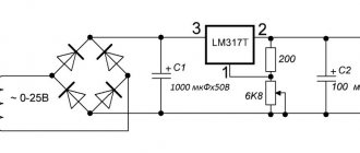
To obtain a complete unit, you should add only three components - a transformer with a voltage on the secondary winding of 24 volts at 220 volts at the input (an important point, which is discussed in detail below) and a current of 3.5-4 A, a radiator for the output transistor and a 24-volt cooler for cooling the radiator at high load current. By the way, I found a diagram of this power supply on the Internet:
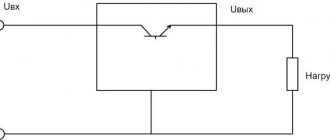
The main components of the circuit include:
- diode bridge and filter capacitor;
- control unit on transistors VT1 and VT2;
- the protection node on transistor VT3 turns off the output until the power supply to the operational amplifiers is normal
- fan power supply stabilizer on 7824 chip;
- A unit for forming the negative pole of the power supply of operational amplifiers is built on elements R16, R19, C6, C7, VD3, VD4, VD5. The presence of this node determines the power supply of the entire circuit with alternating current from the transformer;
- output capacitor C9 and protective diode VD9.
Separately, you need to dwell on some components used in the circuit:
- rectifier diodes 1N5408, selected end-to-end - maximum rectified current 3 Amperes. And although the diodes in the bridge work alternately, it would still not be superfluous to replace them with more powerful ones, for example, 5 A Schottky diodes;
- The fan power stabilizer on the 7824 chip was, in my opinion, not very well chosen - many radio amateurs will probably have 12-volt fans from computers on hand, but 24-volt coolers are much less common. I didn’t buy one, deciding to replace the 7824 with a 7812, but during testing the BP abandoned this idea. The fact is that with an input alternating voltage of 24 V, after the diode bridge and filter capacitor we get 24 * 1.41 = 33.84 Volts. The 7824 chip will do an excellent job of dissipating the extra 9.84 Volts, but the 7812 has a hard time dissipating 21.84 Volts into heat.
In addition, the input voltage for microcircuits 7805-7818 is regulated by the manufacturer at 35 Volts, for 7824 at 40 Volts. Thus, in the case of simply replacing 7824 with 7812, the latter will work on the edge. Here is a link to the datasheet.
Taking into account the above, I connected the available 12 Volt cooler through the 7812 stabilizer, powering it from the output of the standard 7824 stabilizer. Thus, the cooler’s power supply circuit turned out to be, although two-stage, reliable.
Operational amplifiers TL081, according to the datasheet, require bipolar power +/- 18 Volts - a total of 36 Volts and this is the maximum value. Recommended +/- 15.
And this is where the fun begins regarding the 24 Volt variable input voltage! If we take a transformer that, at 220 V at the input, produces 24 V at the output, then again after the bridge and filter capacitor we get 24 * 1.41 = 33.84 V.
Thus, only 2.16 Volts remain until the critical value is reached. If the voltage in the network increases to 230 Volts (and this happens in our network), we will remove 39.4 Volts of DC voltage from the filter capacitor, which will lead to the death of the operational amplifiers.
There are two ways out: either replace the operational amplifiers with others, with a higher permissible supply voltage, or reduce the number of turns in the secondary winding of the transformer. I took the second path, selecting the number of turns in the secondary winding at the level of 22-23 Volts at 220 V at the input. At the output, the power supply received 27.7 Volts, which suited me quite well.
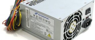
As a heatsink for the D1047 transistor, I found a processor heatsink in the bins. I also attached a 7812 voltage stabilizer to it. Additionally, I installed a fan speed control board. A donor PC power supply shared it with me. The thermistor was secured between the fins of the radiator.
When the load current is up to 2.5 A, the fan rotates at medium speed; when the current increases to 3 A for a long time, the fan turns on at full power and reduces the temperature of the radiator.
Principle of operation
Let's start with the fact that the laboratory power supply uses a transformer with a secondary winding of 24V/3A, which is connected through input terminals 1 and 2 (the quality of the output signal is proportional to the quality of the transformer). The AC voltage from the secondary winding of the transformer is rectified by a diode bridge formed by diodes D1-D4. The ripples of the rectified DC voltage at the output of the diode bridge are smoothed by a filter formed by resistor R1 and capacitor C1. The circuit has some features that make this power supply different from other units in its class.
Instead of using feedback to control the output voltage, our circuit uses an op-amp to provide the required voltage for stable operation. This voltage drops at the output of U1. The circuit operates thanks to the D8 - 5.6 V Zener diode, which here operates at zero temperature coefficient of current. The voltage at the output of U1 drops across the diode D8 turning it on. When this happens, the circuit stabilizes and the voltage of the diode (5.6) drops across resistor R5.
The current that flows through the opera. the amplifier changes slightly, which means the same current will flow through resistors R5, R6, and since both resistors have the same voltage value, the total voltage will be summed up as if they were connected in series. Thus, the voltage obtained at the output of the opera. amplifier will be equal to 11.2 volts. Chain from oper. amplifier U2 has a constant gain of approximately 3, according to the formula A = (R11 + R12) / R11 increases the voltage of 11.2 volts to approximately 33 volts. Trimmer RV1 and resistor R10 are used to set the voltage output so that it does not drop to 0 volts, regardless of the value of other components in the circuit.
Another very important characteristic of the circuit is the ability to obtain the maximum output current that can be obtained from the psu. To make this possible, the voltage drops across the resistor (R7), which is connected in series with the load. The IC responsible for this circuit function is U3. An inverted signal to input U3 equal to 0 volts is supplied through R21. At the same time, without changing the signal of the same IC, you can set any voltage value through P2. Let's say that for a given output the voltage is several volts, P2 is set so that there is a signal of 1 volt at the input of IC. If the load is amplified, the output voltage will be constant and the presence of R7 in series with the output will have little effect due to its low magnitude and due to its position outside the feedback loop of the control circuit. As long as the load and output voltage are constant, the circuit operates stably. If the load is increased so that the voltage on R7 is greater than 1 volt, U3 is turned on and stabilizes to its original parameters. U3 operates without changing the signal to U2 through D9. Thus, the voltage through R7 is constant and does not increase above a predetermined value (1 volt in our example), reducing the output voltage of the circuit. This device is capable of maintaining the output signal constant and accurate, which makes it possible to obtain 2 mA at the output.
Capacitor C8 makes the circuit more stable. Q3 is needed to control the LED whenever you use the limiter indicator. To make this possible for U2 (changing the output voltage down to 0 volts) it is necessary to provide a negative connection, which is done through the circuit C2 and C3. The same negative connection is used for U3. Negative voltage is supplied and stabilized by R3 and D7.
To avoid uncontrollable situations, there is a kind of protection circuit built around Q1. The IC is internally protected and cannot be damaged.
U1 is a reference voltage source, U2 is a voltage regulator, U3 is a current stabilizer.
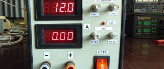
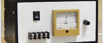
Digital indicator for the block
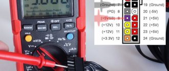
To visualize the voltage and current readings in the load, I used a DSN-VC288 voltammeter, which has the following characteristics:
- measuring range: 0-100V 0-10A;
- operating current: 20mA;
- measurement accuracy: 1%;
- display: 0.28" (Two colors: blue (voltage), red (current);
- minimum voltage measurement step: 0.1 V;
- minimum current measurement step: 0.01 A;
- operating temperature: from -15 to 70 °C;
- size: 47 x 28 x 16 mm;
- operating voltage required for operation of the ampere-voltmeter electronics: 4.5 – 30 V.
Considering the operating voltage range, there are two connection methods:
- If the source of the measured voltage operates in the range from 4.5 to 30 Volts , then the connection diagram looks like this:
- If the source of the measured voltage operates in the range 0-4.5 V or above 30 Volts , then up to 4.5 Volts the amperevoltmeter will not start, and at a voltage of more than 30 Volts it will simply fail, to avoid which you should use the following circuit:
In the case of this power supply, there is plenty to choose from for powering the ampere-voltmeter. The power supply has two stabilizers - 7824 and 7812. Before 7824, the wire length was shorter, so I powered the device from it, soldering the wire to the output of the microcircuit.
PSU circuit with current and voltage adjustments
Schematic diagram
| R1 = 2.2 KOhm 1W |
| R2 = 82 Ohm 1/4W |
| R3 = 220 Ohm 1/4W |
| R4 = 4.7 KOhm 1/4W |
| R5, R6, R13, R20, R21 = 10 KOhm 1/4W |
| R7 = 0.47 Ohm 5W |
| R8, R11 = 27 KOhm 1/4W |
| R9, R19 = 2.2 KOhm 1/4W |
| R10 = 270 KOhm 1/4W |
| R12, R18 = 56KOhm 1/4W |
| R14 = 1.5 KOhm 1/4W |
| R15, R16 = 1 KOhm 1/4W |
| R17 = 33 Ohm 1/4W |
| R22 = 3.9 KOhm 1/4W |
| RV1 = 100K trimmer |
| P1, P2 = 10KOhm linear pontesiometer |
| C1 = 3300 uF/50V electrolytic |
| C2, C3 = 47uF/50V electrolytic |
| C4 = 100nF polyester |
| C5 = 200nF polyester |
| C6 = 100pF ceramic |
| C7 = 10uF/50V electrolytic |
| C8 = 330pF ceramic |
| C9 = 100pF ceramic |
| D1, D2, D3, D4 = 1N5402,3,4 diode 2A – RAX GI837U |
| D5, D6 = 1N4148 |
| D7, D8 = 5.6V Zener |
| D9, D10 = 1N4148 |
| D11 = 1N4001 diode 1A |
| Q1 = BC548, NPN transistor or BC547 |
| Q2 = 2N2219 NPN transistor |
| Q3 = BC557, PNP transistor or BC327 |
| Q4 = 2N3055 NPN power transistor |
| U1, U2, U3 = TL081, operational amplifier |
| D12 = LED diode |
Here is another version of this scheme:
About the wires included in the kit
- The wires of the three-pin connector are thin and made of 26AWG wire - thicker is not needed here. Colored insulation is intuitive - red is the power supply for the module electronics, black is ground, yellow is the measuring wire;
- The wires of the two-contact connector are current measuring wires and are made of thick 18AWG wire.
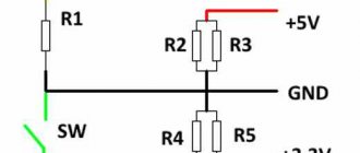
When connecting and comparing the readings with the multimeter readings, the discrepancies were 0.2 Volts. The manufacturer has provided trimmers on the board to calibrate voltage and current readings, which is a big plus. In some instances, non-zero ammeter readings are observed without load. It turned out that the problem can be solved by resetting the ammeter readings, as shown below:
The picture is from the Internet, so please forgive any grammatical errors in the captions. In general, we’ve finished with the circuit design - let’s move on to making the box...
BP forum
- LABORATORY PSU 1-24 V
- POWER SUPPLY FOR PRACTICUM
- PSU DIAGRAM 0-25 VOLTS 0-5 AMPERES
- SEQUENCER DIAGRAM