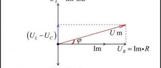
Types of vector diagrams and rules for their construction
Definition 1
A vector diagram is a set of vectors on a complex line that corresponds to complex parameters and/or quantities of an electrical circuit.
Vector diagrams can be:
- Chiseled.
- High quality.
The construction of scatter plots is carried out in compliance with the scale of all quantities according to the results of numerical analysis. The main purpose of scatter plots is to check the calculation results. High-quality vector diagrams are constructed taking into account the relationships between complex quantities. The construction of this type of diagrams, as a rule, replaces or precedes calculations. In high-quality vector diagrams, the values of parameters (or quantities) and the image scale are unimportant. The main requirement for them is that all relationships between quantities are displayed correctly. This type of diagram is one of the main tools for analyzing AC circuits.
Are you an expert in this subject area? We invite you to become the author of the Directory Working Conditions
Vector diagrams are divided into circular and linear. In a circular vector diagram, the locus of the moving points of the end of the vector is a circle or semicircle. In linear vector diagrams, the locus of the end points of a vector is a straight line.
Before constructing a phasor diagram, an equivalent circuit, which is equivalent to a circuit diagram of an electrical circuit, is first drawn and analyzed. On this diagram, each element of the electrical circuit must be marked, and the directions of all voltages and currents are plotted. Vector diagrams of currents and voltages should be drawn on a large scale, the choice of which is made based on the largest calculated or measured value of electric current or voltage.
What is a vector diagram of currents and voltages? How to build a graph
The use of vector diagrams in the analysis and calculation of alternating current circuits makes it possible to consider the processes occurring in a more accessible and visual way, and also, in some cases, significantly simplify the calculations performed.
A vector diagram is usually called a geometric representation of directed segments varying according to a sinusoidal (or cosine) law - vectors that display the parameters and values of the operating sinusoidal currents, voltages or their amplitude values.
Vector diagrams are widely used in electrical engineering, vibration theory, acoustics, optics, etc.
There are 2 types of vector diagrams:
- accurate;
- quality.
Watch an interesting video about vector diagrams below:
Accurate ones are depicted based on the results of numerical calculations, provided that the scales of the actual values correspond. When constructing them, it is possible to geometrically determine the phases and amplitude values of the desired quantities.
Vasiliev Dmitry Petrovich
Professor of Electrical Engineering, St. Petersburg State Polytechnic University
Qualitative diagrams are depicted taking into account the mutual relationships between electrical quantities, without indicating numerical characteristics.
They are one of the main means of analyzing electrical circuits, allowing you to clearly illustrate and qualitatively control the progress of solving a problem and easily establish the quadrant in which the desired vector is located.
For convenience, when constructing diagrams, stationary vectors are analyzed for a certain point in time, which is selected in such a way that the diagram has a form that is easy to understand. The OX axis corresponds to the values of real numbers, the OY axis to the axis of imaginary numbers (imaginary unit). The sinusoid displays the movement of the end of the projection on the OY axis. Each voltage and current corresponds to an eigenvector on the plane in polar coordinates. Its length displays the amplitude value of the current, with the angle being equal to the phase.
The vectors depicted in such a diagram are characterized by an equal angular frequency ω. In view of this, when rotating, their relative position does not change.
Another useful video about vector diagrams:
Therefore, when depicting vector diagrams, one vector can be directed in any way (for example, along the OX axis).
And the rest should be depicted in relation to the original one at different angles, respectively equal to the phase shift angles.
Thus, the vector diagram gives a clear idea of the advance or lag of various electrical quantities.
Let's say we have a current, the value of which varies according to a certain law:
i = Im sin (ω t + φ).
From the origin of coordinates 0 at an angle φ we draw the vector Im, the value of which corresponds to Im. Its direction is chosen so that the vector makes an angle with the positive direction of the OX axis - corresponding to the phase φ.
Abrahamyan Evgeniy Pavlovich
Associate Professor, Department of Electrical Engineering, St. Petersburg State Polytechnic University
The projection of the vector onto the vertical axis determines the value of the instantaneous current at the initial moment of time.
Basically, vector diagrams are depicted for effective values, and not for amplitude values. Vectors of effective values differ quantitatively from amplitude values - in scale, because:
I = Im /√2.
The main advantage of vector diagrams is the ability to simply and quickly add and subtract 2 parameters when calculating electrical circuits.
Visualization of participant connection data on a ray diagram
Let's start first by constructing gray dotted lines to represent all the weak ties between the participants. And then we will do the same actions for the gray solid lines of strong connections. Select the range of cells I3:J43 and select the tool: “INSERT” - “Charts” - “Spot Line”.
The following items should be removed from the diagram: grid, coordinate axes, title and legend.
Then from the additional menu: “WORKING WITH DIAGRAMS” - “CONSTRUCTOR” - “Select data” in the “Select data source” window, use the “Add” button to add the remaining 20 series:
Each line must be assigned the same format. It is convenient to select rows of lines from the additional menu: “WORKING WITH DIAGRAMS” - “FORMAT” - “Current fragment”. From the drop-down list, select the row we need, and below click the “Format Selected” button to start formatting:
Next, add 2 more rows to highlight the selected participants with color. To do this, we use the values of the last table:
Don't forget to change the line colors to green and blue, respectively.
All that remains is to add data signatures. To do this, we use the second table with the base coordinates of the participants’ points when creating another row:
Select the last row, click on the pole next to the diagram and check the “Data Labels” option. It is better to hide the row itself by removing the curl for its lines.
Interactive ray diagram control panel
To create a control panel, we will use a regular slice for an already created smart table. Go to any cell of the smart table on the “Processing” sheet and select the tool: “INSERT” - “Filters” - “Slice”. In the soldered window, check only the “Name” option.
Copy the slice and ray diagram onto the “CHART” sheet and enjoy the finished result:
As you can see in the figure above, only 43 rows were created for the ray diagram of the relationships between market participants. To add a large number of series to the chart, you can create macros; in this case, you can add everything manually.
Preparing data for a ray diagram
As mentioned above, this template will have the ability to visually build connections for up to 20 participants (companies, branches, counterparties, etc.). The template worksheet "Data" provides a table for populating incoming values. For example, let’s fill it out for 14 market participants:
On the same sheet we will create an additional table, which is a matrix of connections of all possible participants, generated by the formula:
With the data preparation completed, we move on to processing.
A set of radius vectors depicting sinusoidally varying emfs, voltages, currents, etc. is called a vector diagram.
Vector diagrams clearly illustrate the progress of solving the problem. With precise construction of vectors, it is possible to determine the amplitudes and phases of the desired quantities directly from the diagram. Approximate (qualitative) construction of diagrams during an analytical solution serves as a reliable control of the correctness of the solution progress and makes it possible to easily determine the quadrant in which the vectors being determined are located.
When constructing vector diagrams for circuits with a series connection of elements, the current vector should be taken as the base (starting) vector (see lecture No. 8), and the voltage vectors on individual elements should be adjusted to it at appropriate angles. For circuits with parallel connection of elements, the voltage vector should be taken as the base (starting) vector (see lecture No. 8), orienting the current vectors in parallel branches relative to it.
To visually determine the magnitude and phase of voltage between different points of an electrical circuit, it is convenient to use topographic diagrams.
They represent points connected according to the electrical circuit diagram on the complex plane, displaying their potentials. On a topographic diagram, which is basically a vector diagram, the order of the voltage vectors strictly corresponds to the order of the elements in the circuit, and the voltage drop vector on each subsequent element is adjacent to the end of the voltage vector on each previous element.
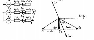
As an example, we will construct a vector diagram of currents, as well as a topographic diagram of potentials for the circuit, the calculation of which was given in lecture No. 5 (see Fig. 1).
Scheme parameters:
With these parameters and a given voltage at the input of the circuit, the found current values (see lecture No. 5) are equal to: ; ; .
When constructing a vector diagram, we will set the scales of currents and voltages (see Fig. 2). A vector diagram can be constructed by having a record of the complex in exponential form, i.e. by modulus and phase values. However, in practice, it is more convenient to carry out constructions using an algebraic form of notation, since in this case the real and imaginary components of a complex quantity are directly plotted on the corresponding axes of the complex plane, determining the position of a point on it.
The construction of a vector diagram of currents is carried out directly on the basis of the known values of their complexes. To construct a topographic diagram, we first carry out the calculation of complex potentials (another option for constructing a topographic diagram involves calculating stress complexes on the circuit elements with subsequent summation of stress vectors along the contour directly on the complex plane).
When constructing a topographic diagram, contours can be traversed in the direction of the current or against it. The second option is used more often.
In this case, taking into account the fact that in electrical engineering it is accepted that current flows from a higher potential to a smaller one, the potential of the desired point is equal to the potential of the previous one plus the voltage drop across the element between these points. If a source of EMF is encountered on the bypass path, then the potential of the desired point will be equal to the potential of the previous one plus the value of this EMF if the direction of the bypass coincides with the direction of the EMF, and minus the value of the EMF if it does not coincide. This follows from the fact that the voltage at the EMF source has the direction opposite to the EMF.
Labeled on the diagram according to Fig. 1 points between the circuit elements e and a and taking the potential of point a as zero ( ), we determine the potentials of these points:
or
Thus, as a result of the calculations performed, it was found that . But the potential difference of points e
and
a is
equal to the voltage U applied to the circuit, and it is equal to 120 V. Thus, Kirchhoff’s second law is satisfied, and therefore the calculations are performed correctly. In accordance with the results obtained, a topographic diagram is constructed in Fig. 2. You should pay attention to the orientation of the vectors that make up the topographic diagram relative to the current vectors: for resistive elements the corresponding vectors are parallel, for inductive and capacitive elements they are orthogonal.
In conclusion, we note that the voltage vectors are oriented relative to the points of the topographic diagram opposite to the positive directions of the voltages relative to the corresponding points of the electrical circuit. In this regard, it is permissible not to indicate the directions of stress vectors on the topographic diagram.
Potential diagram
The potential diagram is used in the analysis of DC circuits. It is a graph of the potential distribution along a section of a circuit or circuit, with the resistance of resistive elements encountered along the path of the branch or circuit being plotted along the abscissa axis, and the potentials of the corresponding points along the ordinate axis. Thus, each point of the section or contour under consideration corresponds to a point on the potential diagram.
Let's consider constructing a potential diagram using the example of the circuit in Fig. 3.
With circuit parameters ; ; ; ; and the currents in the circuit branches are equal to: ; ; .
Let's construct a potential diagram for the contour abcda
.
To select a scale along the abscissa axis, we sum up the resistor resistances along the contour under consideration: after which we determine the potentials of the contour points relative to the potential of an arbitrarily selected point a
, the potential of which is taken to be zero:
Thus, the coordinates of the points of the potential diagram: a(0;0);b(4;-20); c(4;17); d(7;2)
. Taking into account the selected scales in Fig. 4 a potential diagram is plotted for the selected circuit.
Converting Linear Electrical Circuits
To simplify the calculations and increase the clarity of the analysis of complex electrical circuits, in many cases it is rational to subject them to preliminary transformation. Obviously, the transformation should lead to a simplification of the original circuit by reducing the number of its branches and (or) nodes. Such a transformation is called expedient.
In this case, with any transformation methods, the condition of constant currents in the branches of the circuit sections not affected by these transformations must be met. It follows from the latter that if sections of the circuit that do not contain energy sources are subject to transformation, then the powers in the original and equivalent circuits are the same. If the converted sections include energy sources, then in general the powers in the original and converted circuits will be different.
Let's consider the most important cases of transforming electrical circuits.
1. Conversion of series-connected elements
Consider the section of the circuit in Fig. 5, a. When calculating the circuit external to this section, this branch can be reduced to the form in Fig. 5b, where
| (1) |
or
| . | (2) |
In this case, when calculating the equivalent EMF, the kth EMF is taken with a “+” sign if its direction coincides with the direction of the equivalent EMF, and “-” if it does not coincide.
2. Conversion of parallel connected branches
Let us have the diagram in Fig. 6, a.
According to Ohm's law for a section of a circuit with an EMF source
,
Where .
Then
where _
| ; | (3) |
| , | (4) |
Moreover, the EMF and current are written with the “+” sign in (4) if they are directed to the same node as the EMF; otherwise they are written with a “-” sign.
3. Mutual transformations “triangle-star”
In some cases, there may be circuits in which the connections cannot be classified as either serial or parallel (see Fig. 7). In such cases, the transformations are more complex: converting a triangle into a star and vice versa.
To transform a triangle into a star means to replace three resistances connected into a triangle between some three nodes with another three resistances connected into a star between the same points. At the same time, in areas of the circuit not affected by these transformations, the currents should remain unchanged.
Without derivation, we write the formulas for equivalent transformations
| Triangle star | Star triangle |
Literature
- Fundamentals
of circuit theory: Textbook. for universities / G.V. Zeveke, P.A. Ionkin, A.V. Netushil, S.V. Strakhov. –5th ed., revised. –M.: Energoatomizdat, 1989. -528 p. - Bessonov
L.A. Theoretical foundations of electrical engineering: Electric circuits. Textbook for students of electrical engineering, energy and instrument engineering specialties of universities. –7th ed., revised. and additional –M.: Higher school, 1978. –528 p.
Test questions and tasks
- What are vector diagrams?
- What are topographic diagrams and what are they used for?
- What are the similarities and differences between topographic and potential diagrams?
- What is the practical meaning of transforming electrical circuits?
- What is the principle of equivalence of transformations?
- Construct potential diagrams for the left and external contours of the circuit in Fig. 3.
- Assuming in the circuit in Fig. 8 known current and parameters of all its elements, qualitatively construct a vector diagram of currents and a topographic diagram of potentials for it.
- Determine the input resistance of the circuit in Fig. 8 if .
- Determine the resistance of the branches of a triangle equivalent to a star between nodes a, c and d in the circuit in Fig. 8.
- Determine the resistance of the branches of a star equivalent to a triangle in the circuit in Fig. 8, consisting of elements , and .
Answer: .
Answer: ; ; .
Answer: ; ; .
How to Make a Ray Vector Link Diagram in Excel
First, let's take a look at what we are trying to build and visually estimate the amount of work. Looks interesting? Then read on to find out how to create it.
To create a ray diagram in Excel to visually analyze relationships in a network, we need to first understand its different components.
As you can see, the diagram contains the following parts:
- A set of points, each of which represents one stakeholder - network participants.
- A set of grayish thick solid and thin dotted lines representing all relationships between people. Solid lines are strong connections (for example, friends), dotted lines are weak connections (acquaintances).
- A set of green thick and blue dotted lines representing relationships for a selected specific network group member.
- A slicer for selecting a participant's analysis - like a ray diagram control panel.
- A table with summary statistics of the selected person.
Rationale for vector diagram
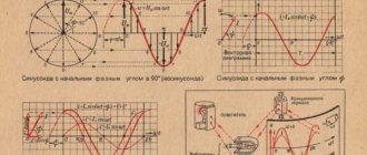
Let us assume that the current is given by the equation
i = Imsin(ωt +Ψ)
Let us draw two mutually perpendicular axes and from the point of intersection of the axes we draw a vector Im , the length of which on a certain scale Mi expresses the amplitude of the current Im :
Im = Im/Mi
We choose the direction of the vector so that with the positive direction of the horizontal axis the vector makes an angle equal to the initial phase Ψ (Fig. 12.10).
The projection of this vector onto the vertical axis determines the instantaneous current at the initial time: i0 = ImsinΨ .
Let's imagine that the vector Im rotates counterclockwise with an angular velocity equal to the angular frequency ω . Its position at any time is determined by the angle ωt + Ψ ,
Then the instantaneous current for an arbitrary moment of time t can be determined by the projection of the vector Im onto the vertical axis at this moment of time.
Next article addition and subtraction of vectors in a vector diagram.
For example, for t = t1
i1 = Imsin(ωt1 +Ψ)
in general
i = Imsin(ωt +Ψ)
We obtained the same equation as the alternating current was specified, which indicates the possibility of depicting the current as a rotating vector when applied to the drawing in the initial position.