Home » Useful tips » Homemade products » Making a control panel for your home and car with your own hands
Now there are special indicator screwdrivers that allow you to determine the voltage in the network. But not every person has such screwdrivers. In this article we decided to tell you how to make a control with your own hands for 12 and 220 volts. With their help, you can easily determine whether there is voltage in the socket, or determine which fuse has failed in the car. In this article you will find basic methods, diagrams and video instructions.
Varieties
There are two types of controls: for home and car. They differ significantly from each other; for a home you can use 220 Volts, while for a car you can only use a 12 Volt control. They are assembled in a similar way, the only difference is the light source that is used. Let's figure out how to make a control with your own hands, and what we need for this. Also read: automatic cabinet lighting
Transistor circuit
For most designs, a generator is used that produces a frequency of 50-56 Hz. It is not recommended to exceed this value.
It depends on the characteristics of the parts used:
- transistors;
- RC or LC filter;
- matching transformer, if provided;
- microcircuits.
The generator produces alternating voltage and controls (switches) power switches from pairs of field-effect transistors. They are connected to a special step-up transformer. When 12 V is supplied to the device, the transistors will begin to swing. An alternating component will appear at the outputs, which will be increased by a transformer to 220-260 V.
The power of the device depends on the number of transistors. It is not recommended to achieve 300 watts of output with only one pair. For normal operation you will need radiators and cooling. It is better to use at least 4 transistors.
Such an inverter does not require adjustment and starts working immediately. Without load, the no-load current does not exceed 300 mA. It is recommended to install transistors through mica (or other) gaskets on radiators. If the device is made on a printed circuit board, then the tracks must be made thick.
Review of a good inverter from 12 volts to 220 volts with a power of 2000 watts. If you have been choosing an inverter for a long time, we recommend that you take a closer look at this model, POWER INVERTER 2000w.
We do home inspections
To make a test for home use, you need to prepare the following materials:
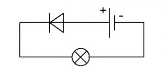
The control connection diagram is as follows.
You just need to connect the wires to the socket and screw in a regular lamp. As you can see, a homemade 220-volt control light has a fairly simple design; even a small child can assemble it with his own hands.
Remember! It is necessary to make high-quality insulation, preferably winding it at the end, so it will be convenient to use. Do not make the tips too large, as they can be accidentally caught by your hand.
See how the professionals do it.
Control circuit using LEDs with a 3.7 V battery with a buzzer
Features of this scheme:
- LEDs are soldered in parallel and counter.
- This control circuit is based on LEDs with a tweeter. Convenient feature.
- The switch is needed to charge the batteries. To do this, you need to connect both the probe and the crocodile to the battery and the charge will go. The switch also prevents self-discharge of batteries in the event of spontaneous contact between the probe and the crocodile.
- The buzzer signals the circuit
- A light bulb and another switch create a load on the desired wire. We can easily find the power “plus”, by analogy with the first control scheme that we discussed above.
For auto
An automobile tester, unlike a household one, performs measuring operations in DC circuits with a supply voltage of 12 V. Therefore, you cannot use a 220 V tester as an automobile probe. But the manufacturing principle will be identical, although it is very convenient to use LED controls instead of light bulbs to diagnose a car.
Due to the technical features of the car's electrical wiring, testing at 12 V, performed according to the principle described above, does not provide complete information about the state of affairs in the circuit. Because of this, auto electrician control can be equipped with the following functional additions:
Rice. 2: modernized auto control
Such a circuit, in addition to monitoring the state of the circuits, allows you to determine the plus or minus at the terminals and the signal intensity. Thanks to the multi-polarity of the LEDs, one of them will light up when touching the positive terminal, and the second will signal when contacting the negative terminal.
To implement such autotest control you will need:
- Connecting wires are selected according to your needs, but professional auto electricians recommend making the length at least 2 m, since the probe has to be installed in hard-to-reach places;
- The probes can be plugs or alligators; for one-time use, you can simply strip the edges of the wires from insulation and do without probes;
- The socket for the light bulb and the light bulb itself are 12V , if the lighting device has a different connection principle, a socket of the appropriate type is installed or the wires are soldered to the terminals of the lamp (LED);
- Button – designed for switching in the control circuit, selected according to the value of the switched current;
- Two LEDs - in this example, multi-colored models are used (red for signaling the positive terminal and blue for the negative);
- Housing – designed to accommodate all the parts and install indicator lights in a visible place; a marker, felt-tip pen or plastic tube of glue can be used as a housing.
The choice of auxiliary elements is limited only by your imagination and the available tools that you find in your garage, apartment or workshop. If you are making a car tester for a specific purpose, you can exclude certain elements from the circuit, thereby greatly simplifying the device. Thus, the simplest control is considered to be a model with one light bulb or low-voltage LED.
Polarity tester
This is a more complex option, for such control you will need two LEDs, you can use smart LEDs (take different colors for convenience), a housing (in this case, use a non-working indicator screwdriver), a soldering iron, and a 1000 Ohm resistor. The control manufacturing process consists of the following stages:
- solder the LEDs and resistor as shown in the figure;
Rice. 6: LED connection diagram - fix the structure on contact springs (the ones that held the light bulb in the screwdriver are perfect);
Rice. 7: Fix the LEDs on the springs - Install the upgraded warning light back into the indicator screwdriver.
Rice. 8: ready control in the indicator
The tester is ready, now when you touch the positive contact, one LED will light up, and when you touch the negative contact, the second one will light up. But remember, the operating rating of such a control is not suitable for 220V household networks - it is determined by the operating rating of the light elements.
An automobile continuity probe (also known as a probe) is a diagnostic device that is widely used in servicing electrical equipment of cars. The main area of application of a continuity probe is as a probe for electrical circuits of a car with high input resistance.
For home network
A distinctive feature of the household network and the devices connected to it is the supply voltage of 220V. Therefore, all spare parts for testing should be selected based on this value.
For spare parts you will need:
- two wires - if you need the control for one-time use, you can also use aluminum wires. If you plan to use it repeatedly, it is better to take stranded copper wire, as it is not afraid of kinks and is more convenient to use.
- light bulb socket - choose only closed models made of insulating material; there should not be any exposed current-carrying elements to which access would be open.
- control light - selected according to the size of the socket base, and if there is a protective casing, according to the dimensions of the cap.
- Probes are not a mandatory element of the control lamp, but they greatly simplify the work, and if there are stops, they also increase safety. As a probe, you can install not only factory products, but also any available means - bolts with screwed nuts, knitting needles, etc.
- a cap or protective casing is also not a mandatory element, but reduces the likelihood of damage to particularly fragile parts. The design can be solid or lattice.
The last two points are relevant for reusable testing; if you want to test the electrical circuits once, you can assemble the tester without probes and a casing.
Production of control for 220V
To assemble the control, you will need the following tools: a screwdriver, a soldering iron, wire cutters or pliers. Depending on the situation, you may only need some of these tools. For example, if soldering is not expected, you can do without a soldering iron. It should be noted that the wires can be soldered to the cartridge rather than screwed, this will make it more reliable.
The manufacturing process consists of the following stages:
- Disassemble the cartridge into its component elements to gain access to the connection points;
- Connect the wires to the terminals of the cartridge, to do this, insert them into the terminal clamp and clamp them tightly with a screwdriver, and if such a connection is not possible, solder the wires to the terminals;
- Assemble the cartridge, lead the control wires into a hole specially designed for this;
- Connect or solder the probes to the wire terminals, insulate the connection or soldering points, the probes themselves must have sufficient insulation to prevent the possibility of touching exposed live parts during work;
- Screw the lamp into the socket and, if necessary, cover it with a protective cover.
Rice.
1: Ready test for 220V The test for 220 V is ready for use for testing wires and electrical circuits. When constantly operating such a control, do not forget to periodically check its functionality in a known-good network that is energized.
Why is control dangerous?
An incandescent lamp is an electrical product that requires careful handling. Therefore, it is installed in lamps that are permanently attached to building structures or have a stable base, for example, in a tabletop version.
The control is portable and easily damaged. She can:
- explode from increased tension;
- slip out of the hands of an electrician, fall and break (often while connected);
- make a short circuit;
- cause a person to be exposed to electric current.
Experienced electricians have tried to take these risks into account and adopted various technical tricks to increase their own safety. But they are all prohibited by modern rules.
Technical background
When connected to voltage, the resistance of the filament changes according to a nonlinear law. At the initial moment, transient processes occur briefly, and then the nominal operating mode is established.
This is explained by the fact that tungsten in a cold and heated state has different electrical resistance. Let's consider this using the example of a popular 60-watt light bulb. It consumes a current of 0.27 amperes, and its filament has a resistance of 815 ohms.
If you measure its resistance in a cold state, the ohmmeter will show about 59 Ohms. The difference is almost 14 times. This property of tungsten eliminates the need for complex ballast control equipment for the lamp, simplifies the design, but requires consideration during operation.
When the voltage exceeds a linear value of 380, the thread most often burns out, but in a worn-out structure it can explode. There are many examples of such damage. They arise where apartment owners save on protection such as voltage control relays.
Human factor
Electricians who use controls at enterprises worked not only on 220-volt networks, but also on 36-volt networks, which are used to illuminate hazardous areas.
The design of the socket and the shape of the bulbs are interchangeable: when working in control, the bulbs were simply twisted to the appropriate voltage. If, when changing workplaces in a 220-volt network, they forgot about this, then the flask exploded. And for some reason small fragments fly straight into your eyes.
Mechanical damage
The glass of the flask is fragile and breaks easily, especially in a portable design. If a stationary lamp has a lamp screwed in and secured, then the control is usually held in the hands. She might slip out.
And a person does not always follow safety rules when working with a tool; he can slip and drop it from his hands or fall with it and cut himself on the glass.
A particular danger is falling with a lamp to which voltage is applied. The filament will break, and the electrodes for its attachment may short-circuit through a random conductive object or the human body. A short circuit immediately occurs with all aggravating circumstances.
Possibility of touching live parts
To create an electrical contact when connecting a control, they usually leave the bare end of the metal on the wire or solder a simple tip with an alligator clip.
This point is under mains voltage and poses a danger.
Homemade warning lamp protection
Considering the risks of working with the controller, experienced electricians tried in every possible way to protect its design:
- put a tin or other lampshade on the cartridge:
- wrapped the flask with tape or rags;
- adapted a hook for suspension;
- a fuse was installed in front of the cartridge to protect against short circuits;
- used to connect wires with a high degree of insulation protection;
- used for connection were probes with safety limiting rings from measuring instruments designed to operate under voltage.
However, even a complete set of all these measures does not allow you to safely perform work with a control lamp. It is more reliable to work with an indicator and a voltmeter.
Connection via adapter/charging
Most chargers or adapters for small appliances provide 12 volts. But you also need to select the current that this device produces. If you have a passport for the radio or a nameplate on it, look at the exact data there.
The car radio requires 12 V and 5-6 A to operate.
Most chargers or adapters for small appliances provide 12 volts. But you also need to select the current that this device produces. If you have a passport for the radio or a nameplate on it, look at the exact data there.
If there is nowhere to get the data, you can focus on the “average”. Typically, a car radio in normal operating mode consumes 5 A. At maximum load, perhaps, the consumption is 10 A. But with such a connection, you cannot squeeze the maximum out of it. So, we are looking for a network adapter or charger that produces 12 V and 5–6 A.
If you find an adapter or charger with suitable parameters, after five to ten minutes the car radio will work from the 220 network
Most of the procedure for connecting a car radio at home is outlined above. We will describe only the immediate actions.
If you find an adapter or charger with suitable parameters, after five to ten minutes the car radio will work from the 220 network
- Cut off the plug. The part that we insert into the equipment from the charger/adapter/adapter/power supply.
- We separate the conductors, being careful not to damage the insulation.
- Use a multimeter to determine plus and minus. You can often find a central wire and braid in the cable. Everything here is just a braid - this is a minus.
- We connect them to the power inputs of the car radio.
- We plug in 220 volts and check how it works.
If you don’t want to cut off the plug, you can simply strip the wires at some distance and draw conclusions. But after checking it is better to insulate the connections.
Another option is not to cut or clean anything. You can simply connect the wires to the plug. The “+” wire is stuck into the central hole, and the minus is the external contact.
Other connection examples, or how to fix them
Another, no less incorrect connection of 12V LEDs can be observed in more complex and powerful devices. With an increase in the number of diodes, manufacturers still continue to rely on battery resistance by simply connecting the elements in series. The most common reason when such devices and crafts are sent in for repair is that a single LED or their entire bunch has burnt out.
You can try to complete the diagram in several ways:
- Connecting one resistor. Such a connection will also not bring the expected result. The thing is that even semiconductor devices produced in the same batch have very noticeable differences. The point is not even that there may be a noticeable difference in the brightness of the LEDs. Here we will talk about such a parameter as voltage drop. Each device is characterized by its own current. The LED with the highest rating will most likely burn out when its current exceeds its rated current. After this, the remaining LEDs powered by 12V will not last long. Then the LED with the next highest current rating will burn out, followed by the remaining one.
- One resistor for each LED. Such a connection of a 12 volt zener diode does not conflict with the rules of circuit design. The currents become independent, but the obvious disadvantage of such a chain is its bulkiness and inappropriate load of elements.
- Chains of series-connected LEDs. Only this option for connecting devices will make it possible to simultaneously achieve maximum compactness with high performance. The only thing worth considering is increasing the supply voltage.
The parameters of LEDs also depend on their color, which must be taken into account when thinking about connecting devices to 12V.
Detailed analysis
The circuit contains a stabilizer that powers the A1 chip. It consists of a chain: R3-VD1-C3, while any similar device with a stabilization indicator of 8-10 volts can be used as a zener diode (VD1).
Please note that capacitors C4 and C5 are installed in parallel. If you do not find them with the same capacity as shown in the diagram, then you can replace them with similar ones (preferably imported) with a capacity of 4700 uF
Capacitor C6 is an element that suppresses high-frequency pulses at the output. It is best to use the K 73-17 brand of domestic production or a similar foreign one for this purpose.
And one last recommendation or nuance. Since a 12-volt network with a consumption of 400 W will generate a current of 40 A, it will be necessary to calculate the cross-section of the wires used. This is especially true for the cable connecting the battery and the converter. Please note that the wire length should be kept to a minimum.
As you can see, making a converter from 12 volts to 220V with your own hands is not very difficult. The circuit is simple, it minimizes the number of parts, which reduces the cost of the device as a whole. Plus its work is more efficient.
Wiring check
Testing conductors using a multimeter is functionally provided in most digital devices of this class. To set the dialing mode, just set the switch to the position marked with the “Buzzer” icon and prepare the measuring chain shown in the figure.
If current flows through the piece of wire being tested, the multimeter will produce an audible signal (buzzer). Naturally, to test a section of a circuit several meters long, you will need an additional wire used to expand the measuring circuit.
Another option for testing phase and neutral linear conductors of considerable length involves twisting them at the remote end of the electrical wiring.
In this case, to check the circuit for an open circuit, it is enough to connect the multimeter's test leads to the free contacts of those ends of the electrical line that are located closer to the device.
The last of the proposed options has the following advantages:
- using this method, you can use a multimeter to immediately test both wires of electrical wiring connected in a series chain;
- checking the wire in this way is much easier than the first way, since you can do without an additional segment that allows for extension of the measuring circuit.
Before checking the electrical wiring hidden in the thickness of the walls, you should first carefully read the wiring diagram. In addition, it is necessary to remove the operating voltage from it by turning off the circuit breaker corresponding to this line.
Video description
This video talks about the useful functions of simple probes and their disadvantages:
It is permissible to work only with a working tool. This doesn't just apply to batteries. It is important that there is no damage to the case. For safe use, experts recommend discarding the insulating tape and replacing the screwdriver with a new one.
As for the network, it needs to be de-energized. Even after a power outage, exposed areas of wiring can only be touched with a testing tool. Moisture in any form must be excluded to eliminate the risk of electric shock.
When checking the electrical wiring, do not touch the metal tip. A voltage with parameters that are characteristic of the network under study passes through it. The body of the pen is made of plastic that can protect a person from electric shock. Otherwise, the manufacturer writes in the instructions how to use the indicator screwdriver. Let's take a closer look at these recommendations.
Checking the serviceability of the tool
In addition to identifying external damage, you need to know how to check the indicator screwdriver for functionality. To do this, just insert the tip into each socket of a known working socket. A working device turns on the indication during contact with the phase.
How to operate different devices
A simple device needs to be applied with a tip to one of the conductors. If there is a contact plate, then you need to touch it with your finger. This is where the work ends, there are no other instructions.
How to use an indicator screwdriver with an LED - the rules are similar to the simplest tool for a contact sample. Only the contact plate is touched to check the serviceability of the tool.
Non-contact testers do not provide for closing the internal circuit. Here the indication is triggered at a distance from the network if there is voltage in a specific area. However, the diode can also light up at an open circuit, which is important to consider during testing. But you can work with low-voltage systems.
Universal testers are a little more complicated. There is a contact plate and a light indication that works when the internal circuit is closed. In addition, there may be a built-in toggle switch for setting one or another operating mode. The marking implies the following:
- O. _ Network testing is performed using the principle of a simple screwdriver with a contact pad.
- L. _ The operating principle is identical to a contactless battery-powered device.
- H. _ High sensitivity mode. You can work with a low response threshold, which helps detect hidden wiring.
There are a few things worth noting. When operating a battery-powered contactless screwdriver, the working part is the so-called heel. This is the end part of the handle. It is carried out over the area under study. If the diode light comes on, there is a phase conductor here.
"Control" for cars. Why a voltmeter will never replace it
We will not consider all these reasons, since we mean that everything was and is in good order, and the problem with the lamp arose precisely after replacing the standard voltage regulator with any other new one, in our case with a three-level voltage regulator. Moreover, if you increase the engine speed, then the control The battery charge lamp immediately goes out, meaning the generator is charging. Since, in principle, this malfunction is not officially a malfunction, you don’t have to do anything; if you accelerate and the warning light goes out, then everything is in order. You can go and not bother.
Yangzhou Pengying Imp.
Principle of operation, what is it for?
The transformer works like this:
- The current passes through the primary coil, which creates a magnetic field.
- All power lines are closed near the coil conductors. Some of these power lines close near the conductors of another coil. It turns out that both are connected to each other using magnetic lines.
- The farther the windings are located from each other, the less force the magnetic coupling occurs between them, since fewer power lines of the first cling to the power lines of the second.
- An alternating current passes through the first (which changes in time and according to a certain law), which means that the magnetic field that is created will also be variable, that is, change in time and according to the law.
- Due to the change in current in the first, a magnetic flux enters both coils, which changes magnitude and direction. An induction of alternating electromotive force occurs. This is stated in the law of electromagnetic induction.
- If the ends of the second are connected to electricity receivers, then a current will appear in the chain of receivers. The first will receive energy from the generator which is equal to the energy given to the second chain. Energy is transmitted through alternating magnetic flux.
A step-down transformer is necessary to convert electricity, namely to reduce its performance, so that the combustion of electrical equipment can be prevented.
Warning lamp
With the advent of cheap multimeters among the testers among the common people, car enthusiasts somehow forgot about an important car enthusiast device - the control lamp. Let's figure out why a multimeter does not replace a control. The simplest example: any lamp in your car stops glowing. Install a new one - it doesn’t light up either. Measure it with a tester - everything is fine, the voltage at the contacts of the headlight socket is 12 volts. The thing is that when measuring voltage, the tester consumes very little current, a fraction of a microampere. And such a current can be generated by dust settling on the contacts.
Features of the probe and its operating principle
The continuity probe is structurally a plastic capsule, inside of which a resistor with a high resistance is placed. A metal rod extends from the plastic base, the end of which is used for direct contact with the contacts of electrical equipment. The device shows the presence of voltage; green and red LED lights located on the plastic case act as indicators. The green LED indicates low circuit resistance, the red LED indicates the presence of voltage.
A car test probe, which is essentially a voltmeter, is indispensable when identifying faults in a car's electrical equipment, as well as when installing new electrical equipment on a vehicle.
The diagnostic device makes it possible to determine the integrity of an electrical circuit or a separate section of it, identify locations of broken connections, unreliable contacts, the location of failed parts, as well as identify a number of other damages. To carry out a quick check of current-carrying equipment, the use of a continuity probe is the most rational and expedient solution.
Car probe 6-24V 110mm “needle” brass AVTODELO
Automotive probe for checking the ignition spark JTC
Automotive probe for checking the ignition spark TEST-M
Car probe for checking the ignition spark 0.5m FORSAGE
Automotive probe 6-24V ROCKFORCE
Automotive probe 6-24V FORSAGE
Car probe 6-24V 120mm “needle” TECHNICIAN
Automotive probe 6-24V 120mm plastic case SPARTA
Automotive probe for checking the ignition spark FORSAGE
Automotive probe 6-24V FORSAGE
How to find phase and zero
Let us recall the voltage distribution diagram in a three-phase network, made.
During military service, during exercises, I had to practically solve a similar problem in the field conditions of a training ground. It was necessary to find phase and zero in a six-core power cable connected to voltage in order to power the lighting circuit from them.
There was no indicator or measuring instruments. A messenger was sent for the light bulbs, and we made do with an ordinary electric razor and a piece of insulated wire.
The test was carried out in two stages:
- determination of phase ends;
- search for zero.
Measurement of phase voltages
The work proceeded according to the following scheme:
- they hammered a piece of metal into the ground next to the cable;
- they attached one contact of an electric razor plug to it;
- a piece of wire was screwed to the second pin and secured with threads;
- with the free end of this conductor we touched all the cores of the cable in turn;
- We marked the three wires on which the razor motor started working - this is how we identified the phase ends and chose the one where it would be easier to install the subsequent circuit.
Search for zero
The electric razor plug was removed from the homemade grounding and, using the freed pin, a contact for current was created alternately on the remaining three wires of the cable with a section of wire connected to the selected phase.
When the engine started, it indicated a working zero, and the other two ends were simply in reserve.
Experienced electricians will see many safety violations in our actions. But this example is given for a different purpose - to show the technical feasibility of solving such a task and its implementation with awareness of the risks and dangers. And in a critical situation, a warning lamp or indicator can be replaced with any power tool, for example.
To better understand the principles of troubleshooting in electrical wiring, I recommend watching the owner’s video “Tips from an Electrician” about the practice of searching for short circuits with a test lamp. I think that they will be useful when using an ordinary voltmeter.
How to use a screwdriver indicator
Well, we looked at three types of indicator screwdrivers, now we’ll look at how to use an indicator screwdriver and test them in operation.
Regular indicator
The pointer of this indicator screwdriver is equipped with two working areas. The first one looks like a flat-head screwdriver - it comes into contact with electrical wiring elements that are energized. The second provides sufficient resistance and is located on the handle of the screwdriver. It also has a two-pole switch.
Let's consider an example in which a phase wire is connected to the first contact, and a neutral wire is connected to the second. The voltage indicator determines which wire the phase is going through.
To determine, it is enough to hold the contact on the handle of the voltage indicator with your thumb, and then bring the working area of the indicator alternately to both contacts of the circuit breaker. In this case, you need to make sure that your thumb remains bare - you should not wear gloves when using the device.
How to use an LED indicator screwdriver
As mentioned above, these indicators are distinguished by the presence of a function not only for contact, but also for non-contact use in the presence of a light warning.
If you are using the classic contact method and you need to find out where the phase is, it is enough to bring the working part closer to both contacts of the circuit breaker. When you bring the device to the zero contact, you will not notice any changes. When you check the phase one, the signal light will immediately light up, which will allow you to immediately find out that there is voltage at this contact.
Do-it-yourself auto electrical repairs
Auto electrics is not a difficult matter at all, you just need to understand a little about electricity and be able to recognize faults. They must be eliminated in time so that the car can move unhindered.
A common problem with a car's electrical system is faulty fuses. If the fuse fails, it must be replaced with a new one. The duplicate must be exactly the same denomination as the new one.
You can also fix some other simple breakdowns yourself. If you cannot cope with more complex problems, then it will be easier to seek help from the nearest auto repair shop, where specialists will diagnose and identify all breakdowns. Afterwards they will make a quality repair.
You can do it yourself:
- Charge the battery;
- Extend the operation of the electric generator;
- Replace some parts;
- Install fog lights.
If there is a burning smell in the car interior, it means that there is a short circuit or fire in the electrical wiring. You cannot move in this state; you must stop and open the hood. After this, disconnect the terminals from the battery and call a tow truck, which will take you to a car service center.
How to do a test: necessary materials
You can check the car yourself or contact the nearest service center. You can do it yourself only with the help of a homemade control. There are two types: for home and car, they differ significantly from each other. If a 220 volt control is suitable for a home, then only 12V is suitable for a car.
The control system for home and car performs the same functions, namely, it detects voltage in the electrical network and some malfunctions of one or another element.
These two types of homemade ones are assembled almost identically, with one difference - the light source. For home testing, a regular 220V lamp is suitable, and a car tester uses a low-power lamp. A diagram is also drawn up that will make it easier to assemble the intended device.
For home control, you also need an electric cartridge, but the wires must be 50 cm long. To take measurements inside the car, you need wires of at least 2 m. For the body of the device, you can purchase a regular cigarette lighter, which can be found in any auto store, but the dipstick can be replaced with a regular self-tapping screw. This device is very easy to use.
Error codes
A group of errors is highlighted separately. Codes exist for timely detection and elimination of breakdowns. When you turn on the ignition, three or four-digit numbers supported by alphabetic abbreviations may appear on the instrument display.
Service equipment is usually used for detailed reading and decoding of errors. The technician, using a computer with a special program, can determine what each symbol means and where to look for a breakdown.
It is impossible to decipher the designations for different cars in one article; each car model has a unique set of combinations that are not duplicated by analogues.
The use of a continuity probe for testing various types of electrical equipment
Battery check
Using a probe, you can check the presence of voltage at the battery terminals. To do this, using an alligator clip, you need to connect to the battery terminal with the “-” sign, and attach the end of the probe to the terminal with the “+” sign.
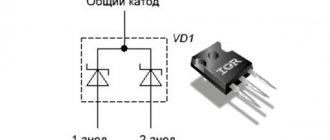
Checking the fuse
To check the fuse, touch one end of its terminal to the positive terminal of the battery, and the end of the probe to its second terminal.
Checking the incandescent lamp
To check an incandescent lamp with a continuity probe, place one terminal of its base to the positive terminal of the battery, and attach the end of the probe to the second. When testing a light bulb with two filaments (such as a car headlight bulb), test them one at a time.