The flow of current in an electrical circuit is carried out through conductors, in the direction from the source to the consumers. Most of these circuits use copper wires and electrical receivers in a given quantity, having different resistances. Depending on the tasks performed, electrical circuits use serial and parallel connections of conductors. In some cases, both types of connections can be used, then this option will be called mixed. Each circuit has its own characteristics and differences, so they must be taken into account in advance when designing circuits.
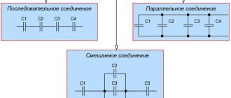
Series connection of conductors
In electrical engineering, the series and parallel connection of conductors in an electrical circuit is of great importance. Among them, a series connection scheme of conductors is often used, which assumes the same connection of consumers. In this case, inclusion in the circuit is performed one after another in order of priority. That is, the beginning of one consumer is connected to the end of another using wires, without any branches.
The properties of such an electrical circuit can be considered using the example of sections of a circuit with two loads. The current, voltage and resistance on each of them should be designated respectively as I1, U1, R1 and I2, U2, R2. As a result, relations were obtained that express the relationship between quantities as follows: I = I1 = I2, U = U1 + U2, R = R1 + R2. The data obtained are confirmed in practice by taking measurements with an ammeter and a voltmeter of the corresponding sections.
Thus, the series connection of conductors has the following individual features:
- The current strength in all parts of the circuit will be the same.
- The total voltage of the circuit is the sum of the voltages in each section.
- The total resistance includes the resistance of each individual conductor.
These ratios are suitable for any number of conductors connected in series. The total resistance value is always higher than the resistance of any individual conductor. This is due to an increase in their total length when connected in series, which also leads to an increase in resistance.
Examples of calculations
As practical examples, we can consider several options for calculating circuit parameters in different connection schemes.
For resistors
The simplest example of a calculation would be a chain of two resistances - 10 Ohms and 100 Ohms, connected in a chain. 12 volts are applied to the circuit.
A series circuit of two resistors.
First you need to find Rtotal, it is equal to the sum of R1 and R2. Rtot=100+10=110 Ohm. Hence the current in the circuit is I=U/R=12/110=0.109 amperes. The drop on each element can be calculated based on the equalities U1=I*R1 and U2=I*R2. Hence U1=1.1 V, and U2=10.9 V. Obviously, U1/U2=R1/R2. The first element will dissipate power P1=U1*I=1.1*0.109=0.12 watts (for practice, a standard component of 0.125 watts is suitable), and the second one will dissipate P2=U2*I=10.9*0.109=1 .19 watts (for practical implementation you will need a two-watt power supply).
If you connect these same two resistors in parallel and apply the same voltage, the parameters will be distributed differently.
Connecting elements in parallel.
First you need to determine Rtot=R1*R2/(R1+R2)=110*10/(110+10)=1100/120=9.17 Ohm (less than the smallest value of 10 Ohm). The total current will be I=U/Rtotal=12/9.17=1.31 amperes. Through the first element I1=U/R1=12/10=1.2 amperes will flow, through the second I2=U/R2=12/100=0.12. Obviously, I1+I2=I (taking into account rounding errors). The power required is:
- P1=I1*U=1.2*12=14.2 watts;
- P2=I2*U=0.12*12=1.42 watts.
If there is a mixed connection of elements, you must first convert the circuit to the same type - parallel or serial. Let there be a diagram of the following type.
Conversion of a mixed circuit.
In this case, it is convenient to replace the parallel assembly of R1 and R2 with a resistor with an equivalent resistance of R12, and R3 and R4 with R34. First, R12=R1*R2/(R1+R2)=9.17 Ohm is found. Using the same method, R34=150*5/(150+5)=4.8 Ohm is calculated. Then the total resistance of the equivalent circuit will be equal to R12+R34=9.17+4.8=13.97 Ohms.
Hence I=U/R=12/13.97=0.86 amperes. On the “garland” R1R2 the drop is U12=I*R12=0.86*9.17=7.87 volts, and on R3R4 the drop will be U34=I*R34=0.86*4.8=4.13 volts. Next, we need to return to the original circuit and consider separately the section of the R1R2 circuit with the found parameters.
Section of the circuit containing R1 and R2.
Hence I1=U/R1=7.87/10=0.787 amperes, I2=U/R2=7.87/100=0.0787 amperes. By power – P1=U*I1=7.87*0.787=6.2 watts, P2= U*I2=7.87*0.0787=0.62 watts.
The section containing the R3R4 elements is calculated in the same way.
For light bulbs
Using exactly the same methods, you can calculate the parameters of a circuit consisting of two or more incandescent light bulbs - in practice, this situation can be encountered more often. But there are two problems. The first of them is that the filament resistance is not indicated on the light bulbs and in the technical data on them. It will have to be recalculated based on the rated voltage and power. Since P=U*I, and I=U*R, then P=U2/R, and R=U2/P. So, for a 10-watt, 12-volt light bulb, the filament resistance will be 122/10=144/10=14.4 ohms. You can calculate the characteristics of a circuit for two light bulbs connected in series and in parallel.
Connecting lamps in a chain.
In the first case, the current flowing through each lamp will be common and equal to I=U/Rtotal=12/(14.4+14.4)=12/28.8=0.42 A. U/2 will drop at each lamp =6 volts. And the electrical power of each element will be 0.42 * 6 = 2.5 W, which is ¼ of the nominal value of the light bulb. This decrease was due to a twofold decrease in current and a twofold decrease in voltage. Naturally, the light bulbs will not glow at full intensity. To bring the brightness of the glow to normal, you will have to double the voltage, which will simultaneously double the current.
Connecting two light bulbs in parallel.
If the light bulbs are connected in parallel, then the nominal level of 12 volts will drop on each of them. I=U/R= 12/14.4=0.83 A will flow through each element, and the power on each light bulb will be equal to P=U*I=12*0.83=10 watts, that is, the nominal value. And each thread will shine at full intensity. But the entire circuit will consume 20 watts and 0.83 * 2 = 1.66 A will flow through it, which is twice the value for one lamp.
There is a second problem. In general, resistance depends on current and applied voltage, but for incandescent lamps this dependence is pronounced. The thread in the cold state has a low resistance, and reaches the nominal value when warmed up in the nominal mode. Therefore, the above calculations are correct only for a standard voltage of 12 volts . Under other conditions, the characteristics of the lamp will be different, and, by and large, the calculation for the parallel case is inaccurate - the filament resistance will be less than 14.4 Ohms. But this property allows the lamp to be used as a current stabilizer - as its value increases, the filament will heat up, the resistance will increase, and the current will drop to approximately the previous level. When it decreases, the reverse process will occur with a decrease in the filament level of the light bulb.
We recommend watching the video lesson “Simply Physics”
For LEDs
The situation with LEDs is even more complicated. Unlike light bulbs, they stabilize the voltage, and not always, but only after opening. In other words, first, when the voltage on the series circuit (LED + resistor) increases, it behaves according to Ohm’s law. After the LED opened (and began to glow), the increase in drop across it stopped, and the increase in voltage on the circuit leads to an increase in current and an increase in U across the resistor. On the semiconductor device, the voltage remains stable (depending on the manufacturing technology - from 1.2 to 3 volts or higher), although the current through it also increases.
Distribution of drops before opening and after opening the LED.
As you master calculation techniques, you can learn to analyze increasingly complex circuits containing both parallel and series connections of elements. Then you can move on to the next stage - analysis and calculation of devices containing reactive (and subsequently nonlinear) components.
Parallel connection of conductors
In electrical networks, conductors can be connected in various ways: in series, in parallel and in combination. Among them, a parallel connection is an option when the conductors at the starting and ending points are connected to each other. Thus, the beginnings and ends of the loads are connected together, and the loads themselves are located parallel to each other. An electrical circuit may contain two, three or more conductors connected in parallel.
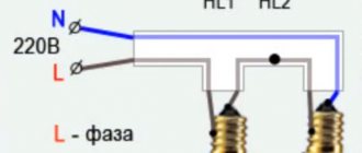
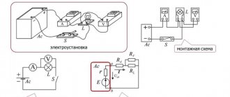
If we consider a series and parallel connection, the current strength in the latter can be studied using the following circuit. Take two incandescent lamps that have the same resistance and are connected in parallel. For monitoring, each light bulb is connected to its own ammeter. In addition, another ammeter is used to monitor the total current in the circuit. The test circuit is supplemented by a power source and a key.
After closing the key, you need to monitor the readings of the measuring instruments. The ammeter on lamp No. 1 will show the current I1, and on lamp No. 2 the current I2. The general ammeter shows the current value equal to the sum of the currents of individual, parallel-connected circuits: I = I1 + I2. Unlike a series connection, if one of the bulbs burns out, the other will function normally. Therefore, parallel connection of devices is used in home electrical networks.
EXAMPLES OF TASKS
Part 1
1. The figure shows a diagram of a section of the electrical circuit AB. Two resistors with resistances \( R_1 \) and \( R_2 \) are connected in parallel to this circuit. The voltages across the resistors are \( U_1 \) and \( U_2 \), respectively.
Which formula can be used to determine the voltage U in section AB?
1) \( U=U_1+U_2 \) 2) \( U=U_1-U_2 \) 3) \( U=U_1=U_2 \) 4) \( U=\frac{U_1U_2 }{U_1+U_2} \)
2. The figure shows a diagram of an electrical circuit containing two resistors connected in parallel with resistance \( R_1 \) and \( R_2 \). Which of the following relationships is true for such a connection of resistors?
1) \( I=I_1=I_2 \) 2) \( I=I_1+I_2 \) 3) \( U=U_1+U_2 \) 4) \( R=R_1+R_2 \)
3. The figure shows a diagram of an electrical circuit. Two resistors with resistance R} and R2 are connected in series to this circuit. Which of the following relationships is true for such a connection of resistors?
1) \( U=U_1+U_2 \) 2) \( I=I_1+I_2 \) 3) \( U=U_1=U_2 \) 4) \( R=\frac{R_1R_2}{R_1+R_2 } \)
4. The figure shows a diagram of an electrical circuit. Two resistors with resistances \( R_1 \) and \( R_2 \) are connected in series to this circuit. Which of the following relationships is true for such a connection of resistors?
1) \( U=U_1=U_2 \) 2) \( I=I_1+I_2 \) 3) \( I=I_1=I_2 \) 4) \( R=\frac{R_1R_2}{R_1+R_2 } \)
5. The figure shows a diagram of an electrical circuit. Two identical resistors with resistance \( R_1 \) are connected in parallel to this circuit. Which formula can be used to determine the total resistance of the circuit \( R \)?
1) \( R=R_1{}^2 \) 2) \( R=2R_1 \) 3) \( R=\frac{R_1}{2} \) 4) \( R =\sqrt{R_1} \)
6. The total resistance of the circuit section shown in the figure is 9 ohms. The resistances of resistors \( R_1 \) and \( R_2 \) are equal. What is the resistance of each resistor?
1) 81 Ohm 2) 18 Ohm 3) 9 Ohm 4) 4.5 Ohm
7. What is the resistance of a section of a circuit containing three series-connected resistors of 9 ohms each?
1) 1/3 Ohm 2) 3 Ohm 3) 9 Ohm 4) 27 Ohm
8. What is the total resistance of the circuit section shown in the figure, if \( R_1 \) = 1 Ohm, \( R_2 \) = 10 Ohm, \( R_3 \) = 10 Ohm, \( R_4 \ ) = 5 Ohm?
1) 9 Ohm 2) 11 Ohm 3) 16 Ohm 4) 26 Ohm
9. What is the total resistance of the circuit section shown in the figure if \( R_1 \) = 1 Ohm, \( R_2 \) = 3 Ohm, \( R_3 \) = 10 Ohm, \( R_4 \) = 10 Ohm?
1) 9 Ohm 2) 10 Ohm 3) 14 Ohm 4) 24 Ohm
10. If the rheostat slider (see diagram) is moved to the left, then the current strength
1) in the resistor \( R_1 \) will decrease, and in the resistor \( R_2 \) will increase 2) will increase in both resistors 3) in the resistor \( R_1 \) will increase, and in the resistor \( R_2 \) will decrease 4) will decrease in both resistors
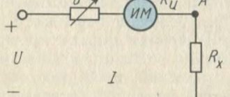
11. The figure shows an electrical circuit consisting of a current source, a resistor and a rheostat. How do its resistance, the current in the circuit and the voltage across resistor 1 change when the rheostat slider is moved to the right?
For each physical quantity, determine the corresponding nature of change. Write down the selected numbers for each physical quantity in the table. The numbers in the answer may be repeated.
PHYSICAL QUANTITY A) resistance of rheostat 2 B) current in the circuit B) voltage across resistor 1
NATURE OF CHANGE 1) increases 2) decreases 3) does not change
12. Establish a correspondence between physical quantities and the correct electrical circuit for measuring these quantities when two resistors \( R_1 \) and \( R_2 \) are connected in series. Write down the selected numbers in the table under the corresponding letters. The numbers in the answer may be repeated.
PHYSICAL QUANTITIES A) current in the resistor \( R_1 \) and \( R_2 \) B) voltage across the resistor \( R_2 \) B) total voltage across the resistors \( R_1 \) and \( R_2 \)
Part 2
13. Three resistors are connected as shown in the figure. Resistor resistances \( R_1 \) = 10 Ohm, \( R_2 \) = 5 Ohm, \( R_3 \) = 5 Ohm. What is the voltage across resistor 1 if the ammeter shows a current of 2 A?
Laws of series and parallel connection of conductors
These laws concerning both types of conductor connections have been partially discussed earlier.
For a clearer understanding and perception in a practical sense, series and parallel connection of conductors, formulas should be considered in a certain sequence:
- A series connection assumes the same current in each conductor: I = I1 = I2.
- Ohm's law explains the parallel and series connection of conductors in each case in its own way. For example, with a series connection, the voltages on all conductors will be equal to each other: U1 = IR1, U2 = IR2. In addition, with a series connection, the voltage is the sum of the voltages of each conductor: U = U1 + U2 = I(R1 + R2) = IR.
- The total resistance of a circuit in a series connection consists of the sum of the resistances of all individual conductors, regardless of their number.
- With a parallel connection, the voltage of the entire circuit is equal to the voltage on each of the conductors: U1 = U2 = U.
- The total current measured in the entire circuit is equal to the sum of the currents flowing through all conductors connected in parallel: I = I1 + I2.
Mixed
Parallel and series connections of conductors can be combined in the same circuit. For example, elements connected in parallel can be connected in series with another resistor or group of resistors. This is a mixed compound. The total resistance of the circuits is calculated by separately summing the values for the parallel connected unit and for the series connection.
Moreover, the equivalent resistances of series-connected elements are first calculated, and then the total resistance of parallel sections of the circuit is calculated. Serial connection in calculations takes priority. These types of electrical circuits are quite common in various devices and equipment.
Having familiarized yourself with the types of connections of circuit elements, you can understand the principle of organization of circuits of various electrical devices. Parallel and serial connections have a number of features in the calculation and operation of the entire system. Knowing them, you can correctly use each of the presented types to connect elements of electrical circuits.
What happens to a circuit if it includes capacitors rather than resistors?
When they are connected in series, the following situation is observed: charges from the pluses of the power source are supplied only to the outer plates of the outer capacitors. Those that are between them simply transfer this charge along the chain. This explains the fact that identical charges appear on all plates, but with different signs. Therefore, the electric charge of each capacitor connected in series can be written as follows:
In order to determine the voltage on each capacitor, you will need to know the formula: U = q / C. In it, C is the capacitance of the capacitor.
The total voltage obeys the same law that is valid for resistors. Therefore, replacing the voltage with the sum in the capacitance formula, we get that the total capacitance of the devices must be calculated using the formula:
You can simplify this formula by reversing the fractions and replacing the voltage-to-charge ratio with capacitance. The result is the following equality: 1 / C = 1 / C 1 + 1 / C 2.
The situation looks somewhat different when the capacitors are connected in parallel. Then the total charge is determined by the sum of all charges that accumulate on the plates of all devices. And the voltage value is still determined according to general laws. Therefore, the formula for the total capacitance of parallel-connected capacitors looks like this:
C = (q 1 + q 2) / U.
That is, this value is calculated as the sum of each of the devices used in the connection:
Total resistance Rtotal
To calculate the total resistance of a mixed connection:
- The circuit is divided into sections with only parallel or only serial connections.
- The total resistance is calculated for each individual section.
- Calculate the total resistance for the entire mixed connection circuit.
This is what it will look like for Scheme 1:
There is also a faster way to calculate the total resistance for a mixed connection. You can, in accordance with the diagram, immediately write the formula as follows:
- If the resistors are connected in series, add them together.
- If resistors are connected in parallel, use the symbol “||”.
- Substitute the formula for a parallel connection where the symbol “||” appears.
This is what it will look like for Scheme 1:
After substituting the parallel join formula instead of “||”:
Total resistance Rtotal
With this connection, a separate current will flow through each resistor. The strength of this current will be inversely proportional to the resistance of the resistor. As a result, the total conductivity of such a section of the electrical circuit increases, and the total resistance, in turn, decreases.
Thus, when connecting resistors with different resistances in parallel, the total resistance will always be less than the value of the smallest individual resistor.
Formula for total conductivity when connecting resistors in parallel:
Formula for equivalent total resistance when connecting resistors in parallel:
For two identical resistors, the total resistance will be equal to half of one individual resistor:
Accordingly, for n identical resistors, the total resistance will be equal to the value of one resistor divided by n.
Types of connections
There are several ways to connect conductors to each other. This or that case is used depending on the type of chain being assembled. It is accepted that the current moves from the positive pole of the energy source to the negative one. This is a conditional position, it is due to the fact that scientists learned about electric current earlier than about the particle involved in charge transfer - the electron. Therefore, any circuit will consist of at least three elements: source, conductor, load. The latter is understood as a receiver that converts electricity into useful work.
Connecting the elements of an electrical circuit can be done in two ways:
- Parallel - all elements are connected with one of the terminals to one point, and with the second to a common one, but a different one.
- Serial - all conductors are connected in series one after another, that is, in a straight line. The input of one element is connected to the input electrode of the other.
You can determine what type of information is used quite simply using a multimeter turned on in diode testing mode. If, during measurement, two points of the conductor are short-circuited with two others, it means that the connection is made in parallel.
From a physics point of view, the connection of conductors determines the path of charge carriers. So, when a potential difference occurs, the work of moving charges, free electrons begin to move in one direction. At the same time, in some places, branching points of the conductive line, their redistribution occurs. This process can be quite simply understood by imagining the circulation of water through closed pipes. So the electric current passes through all the branches and collects at one point.
Thus, the current source will always be connected in parallel to the electrical circuit. Briefly, the path of a charged particle can be described as follows. A charge comes out of the generator, which, under the influence of electromagnetic force, enters the conductor. Next, the generated current begins to move through all conducting parts of the circuit, bifurcating and reconnecting at various points. Afterwards it goes to the load. Electricity is converted in it, and its remains again flow through the conductor to the other terminal of the generator.
Calculation of the inductive reactance of the coil
Any inductance, incl. coil provides some resistance to alternating current. How to calculate it was described above. From the formula XL=2pfL it is clear that the resistance of the inductor primarily depends on the frequency of the current flowing through it and its inductance. Moreover, the relationship with both parameters is directly proportional.
Frequency is a characteristic of the external environment; the inductance of the coil depends on a number of its geometric properties:
Where:
- u0 – magnetic permeability of vacuum – 4p*10-7 H/m;
- ur – relative permeability of the core;
- N – number of throttle turns;
- S – its cross section in m2;
- l is the length of the coil in meters.
Having the above-described formulas and information about the material and dimensions of the coil, you can fairly accurately estimate its inductive reactance without any measuring instruments.
Additional Information. Some digital multimeters have an inductance mode. This feature is rare, but sometimes it turns out to be very useful. Therefore, when choosing a device, you should pay attention to whether it is capable of measuring inductance.
General information
The directed movement of charge carriers is called electric current. In order for it to appear, a source of electromotive force—energy—is needed. But bringing the material under the influence of an external force is not enough. For example, metals conduct electricity well, but plastics do not.
Any physical body consists of electrons and atoms. In turn, the latter are formed with the help of protons and neutrons. Conventionally, it is believed that an electron has a negative charge, and an atom has a positive charge . In this case, the minus particle rotates in an orbital and is held in place by the forces of interatomic interaction. The so-called nucleus is generally neutral due to the fact that the number of negatively charged particles coincides with the number of positive protons.
But in some materials there are electrons that are not attached to atoms. They are called free. It is their quantity that determines the conductivity of a substance. When an electromagnetic field is applied, free carriers begin to move in one direction. This changes the potential energy and current begins to flow.
All substances in physics are divided into three large classes:
- dielectrics - materials that do not conduct electric current;
- semiconductors - substances in which conductivity appears only when certain additional conditions are created;
- conductors are physical bodies that have a large number of free electrons and, because of this, conduct electric current well.
In addition, conductors are also called parts of electrical circuits that connect various radio components to each other. For example, copper, aluminum, silver and platinum materials can be used.
The characteristic of reverse conductivity is electrical resistance. This value determines the ability of the conductor to prevent the passage of current. In addition, there is also a radio component called a resistor. It is used specifically for introducing active resistance into an electrical circuit.