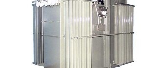
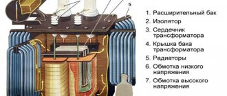
Oil-filled transformers are a special type of device that are used primarily when operating in areas with unusual temperatures and high humidity.
They are demanding in terms of voltage, current and load, so the question of what load is allowed for oil transformers is quite common among specialists. It is not possible to determine it in absentia; it is necessary to pay attention to the technical characteristics and conditions, features of its use, and individual nuances.
What are oil transformers and where are they used?
Oil transformers are used to operate in unusual environmental conditions. They will be the best choice when you have to work at low or high temperatures, in environments with high humidity characteristics. In particular, the oil transformer operates at temperatures up to 40 degrees with a plus sign and 60 degrees with a minus sign.
The device with oil inclusions is placed in the open air, since it will not be spoiled by environmental precipitation. The mechanism parts are reliably protected from the aggressive effects of snow, rain, and lightning by a special thick case. The temperature regime for the operation of the transformer is extended, so devices of this type are used for combination with mast and pole type substations.
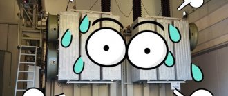
The quality of transformer oil determines the uninterrupted operation and efficiency of equipment. The addition of non-original fluid, the ingress of impurity particles or dust, dirt leads to a decrease in the characteristics of electrolytes. As a result, holes appear between the equipment housing and the winding. Due to the minimum oil level, it begins to exceed the maximum temperature. Whether or not overloading standard oil transformers in emergency modes is allowed is a controversial issue. This is possible, but it will have a detrimental effect on the operation of the device.
Important characteristics during the operation of the equipment are the presence of correct insulation of the oil and the windings themselves, the establishment of the correct temperature and humidity conditions. Special installed monitoring systems cope with this. Online technology monitors the set temperature, analyzes the content of impurities in oil and gas, and monitors humidity. Emergency mode is activated if the parameters do not meet the standards. You cannot turn on the load - this will lead to failure.
5.3. RULES FOR TECHNICAL OPERATION OF POWER PLANTS AND NETWORKS OF THE RUSSIAN FEDERATION
5.3. Power transformers and oil shunt reactors
5.3.1. When operating transformers (autotransformers) and shunt oil reactors, the conditions for their reliable operation must be met. Loads, voltage levels, temperatures of individual elements of transformers (reactors), oil characteristics and insulation parameters must be within the established standards; cooling devices, voltage regulation, and other elements must be kept in good condition.
5.3.2. It is necessary to monitor the correct installation of transformers (reactors) equipped with gas protection devices. The cover must have a rise towards the gas relay of at least 1%, and the oil line to the expander must have a rise of at least 2%. The exhaust pipe cavity must be connected to the expander cavity. If necessary, the membrane (diaphragm) on the exhaust pipe must be replaced with a similar one supplied by the manufacturer.
5.3.3. Stationary fire extinguishing equipment, oil receivers, oil drains and oil collectors must be in good condition.
5.3.4. The station (substation) numbers must be indicated on the tanks of outdoor transformers and reactors. The same numbers should be on the doors and inside transformer points and chambers.
The phase colors must be applied to the tanks of single-phase transformers and reactors. Transformers and reactors for outdoor installations should be painted in light colors with paint that is resistant to weathering and oil.
5.3.5. The electric motors of cooling devices for transformers (reactors) must be powered, as a rule, from two sources, and for transformers (reactors) with forced oil circulation - using an automatic transfer switch.
5.3.6. Load voltage control devices (OLTC) of transformers must be in automatic mode. By decision of the technical manager of the power system, it is allowed to install a non-automatic voltage regulation mode by remotely switching the on-load tap changer from the control panel, if voltage fluctuations in the network are within the limits that satisfy the requirements of electricity consumers.
Switching the on-load tap-changer device of a transformer under voltage manually (with a handle) is not allowed.
5.3.7. Ventilation of transformer substations and chambers must ensure the operation of transformers in all rated modes.
5.3.8. On transformers and reactors with forced circulation of air and oil (DC type cooling) and on transformers with forced circulation of water and oil (C type cooling), cooling devices must be automatically turned on (off) simultaneously with the transformer or reactor on (off). Forced oil circulation must be continuous regardless of the load. The procedure for turning on (off) cooling systems must be determined by the factory instructions.
It is not allowed to operate transformers and reactors with artificial cooling without switched on alarm devices for stopping the circulation of oil, cooling water or stopping the fans.
5.3.9. On transformers with forced air circulation and natural oil circulation (cooling system D), the fan motors should automatically turn on when the oil temperature reaches 55 degrees. C or rated load, regardless of oil temperature and switches off when the oil temperature drops to 50 degrees. C, if the load current is less than the rated one.
The operating conditions of transformers with the blower switched off must be determined by the factory instructions.
5.3.10. When oil-water cooling of transformers, the oil pressure in the oil coolers must exceed the pressure of the water circulating in them by at least 0.1 kgf/cm2 (10 kPa) at a minimum oil level in the transformer expander.
The water circulation system must be turned on after turning on the working oil pumps at a temperature of the upper layers of oil not lower than 15 degrees. C and turns off when the oil temperature drops to 10 degrees. C, unless otherwise specified in the factory technical documentation.
Provisions must be made to prevent oil coolers, pumps and water lines from freezing.
5.3.11. The oil in the conservator of an idle transformer (reactor) should be at the level of the mark corresponding to the temperature of the oil in the transformer (reactor).
5.3.12. At rated load, the temperature of the upper layers of oil should be (unless other temperature values are specified by the manufacturers) for the transformer and reactor with DC cooling - no higher than 75 degrees. C, with natural oil cooling M and cooling D - no higher than 95 degrees. WITH; For transformers with C cooling, the oil temperature at the inlet to the oil cooler should be no higher than 70 degrees. WITH.
5.3.13. Continuous operation of transformers is allowed (with a power not exceeding the rated one) at a voltage on any branch of the winding that is 10% higher than the rated voltage for a given branch. In this case, the voltage on any winding should not be higher than the maximum operating voltage.
For autotransformers with neutral taps for voltage regulation or intended to operate with series regulation transformers, the permissible voltage increase must be specified by the manufacturer.
5.3.14. For oil transformers, long-term overcurrent of any winding is allowed by 5% of the rated branch current, if the voltage on the branch does not exceed the rated one.
In addition, for transformers, depending on the operating mode, systematic overloads are allowed, the value and duration of which are regulated by the standard operating instructions for transformers and the manufacturers' instructions.
In those autotransformers, to the low voltage windings of which a generator, synchronous compensator or load is connected, the current control of the common part of the high voltage winding must be organized.
5.3.15. In emergency modes, short-term overload of transformers above the rated current is allowed for all cooling systems, regardless of the duration and value of the previous load and the temperature of the cooling medium within the following limits:
Oil transformers Current overload, %………………. 30 45 60 75 100 Overload duration, min. ……….. 10 Dry transformers Current overload, % ………………. 20 30 40 50 60 Overload duration, min. ……….. 60 45 32 18 5
Permissible long-term overloads of dry-type transformers are established by the factory instructions.
5.3.16. In case of emergency shutdown of cooling devices, the operating mode of transformers is determined by the provisions of the factory documentation.
5.3.17. Turning on transformers at rated load is allowed:
with cooling systems M and D at any negative air temperature;
with DC and C cooling systems at ambient temperatures not lower than minus 25 degrees. C. At lower temperatures, the transformer must be preheated by switching on a load of about 0.5 rated without starting the oil circulation system until the temperature of the upper oil layers reaches minus 25 degrees. C, after which the oil circulation system must be turned on. In emergency conditions, it is allowed to turn on the transformer at full load, regardless of the ambient temperature;
with a cooling system with directed oil flow in the windings of transformers NDC, NTs in accordance with factory instructions.
5.3.18. The on-load tap-changer switching devices of transformers are allowed to be put into operation at a temperature of the upper oil layers of minus 20 degrees. C and above (for submersible resistor on-load tap-changers) and minus 45 degrees. C and higher (for on-load tap-changer devices with current-limiting reactors, as well as for switching devices with a contactor located on the support insulator outside the transformer tank and equipped with an artificial heating device).
The operation of on-load tap-changer devices must be organized in accordance with the provisions of the manufacturers' instructions.
5.3.19. For each electrical installation, depending on the load schedule, taking into account the reliability of power supply to consumers and the minimum of energy losses, the number of simultaneously operating transformers must be determined.
In distribution power networks with voltages up to 15 kV inclusive, measurements of loads and voltages of transformers must be organized during periods of maximum and minimum loads. The timing and frequency of measurements are established by the technical manager of the power facility.
5.3.20. The neutrals of the windings of 110 kV and higher autotransformers and reactors, as well as transformers of 330 kV and higher, must operate in solid grounding mode.
It is allowed to ground the neutral of transformers and autotransformers through special reactors.
Transformers of 110 and 220 kV with a neutral test voltage of 100 and 200 kV, respectively, can operate with an ungrounded neutral provided it is protected by a surge arrester. When justified by calculations, it is allowed to work with an ungrounded neutral of 110 kV transformers with a neutral test voltage of 85 kV, protected by a surge arrester.
5.3.21. When a gas relay is triggered by a signal, an external inspection of the transformer (reactor) must be carried out, gas must be selected from the relay for analysis and testing for flammability. To ensure the safety of personnel when sampling gas from the gas relay and identifying the reason for its operation, the transformer (reactor) must be unloaded and turned off. The time it takes to unload and disconnect the transformer should be minimal.
If the gas in the relay is non-flammable, there are no signs of damage to the transformer (reactor), and its shutdown caused a lack of electricity supply, the transformer (reactor) can be immediately put into operation until the reason for the gas relay triggering the signal is determined. The duration of operation of the transformer (reactor) in this case is established by the technical manager of the power facility.
Based on the results of gas analysis from the gas relay, chromatographic analysis of the oil, and other measurements (tests), it is necessary to establish the reason for the gas relay to respond to a signal, determine the technical condition of the transformer (reactor) and the possibility of its normal operation.
5.3.22. In the event of automatic shutdown of the transformer (reactor) due to the action of protection against internal damage, it can be put into operation only after inspection, testing, gas and oil analysis and elimination of identified violations.
If a transformer (reactor) is switched off by protections whose operation is not related to its damage, it can be switched on again without checks.
5.3.23. Transformers with a capacity of 1 MVA or more and reactors must be operated with a system of continuous oil regeneration in thermosyphon or adsorption filters.
The oil in the transformer conservator (reactor), as well as in the tank or conservator of the on-load tap-changer, must be protected from direct contact with ambient air.
For transformers and reactors equipped with special devices that prevent oil moisture, these devices must be constantly turned on, regardless of the operating mode of the transformer (reactor). The operation of these devices must be organized in accordance with the manufacturer's instructions.
The oil of oil-filled bushings must be protected from oxidation and moisture.
5.3.24. The transformer (reactor) must be connected to the network by pushing to full voltage.
Transformers operating in a block with a generator can be turned on together with the generator by raising the voltage from zero.
5.3.25. Inspections of transformers (reactors) without shutdown are carried out within the time limits established by the technical manager of the power facility, depending on their purpose, installation location and technical condition.
5.3.26. Repair of transformers and reactors (overhaul, current) and their components (on-load tap-changer, cooling system, etc.) is carried out as necessary, depending on their technical condition, determined by measurements, tests and external inspection.
Repair periods are set by the technical manager of the energy system (energy facility).
5.3.27. Preventive testing of transformers (reactors) must be carried out in accordance with the scope and standards of electrical equipment testing and factory instructions.
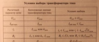
Permissible loads and overloads in transformers
Technical characteristics are determined depending on the nominal values at which the wear of structural parts will occur within 20 years. As a result of using the device within wide limits, it will not only not show efficiency and will work intermittently, but will also fail. Natural wear is observed in the windings, which will no longer show their nominal values when an electrical impulse passes through.
An oil transformer can be used when the highest temperature of its winding does not exceed 98 degrees. If the air temperature increases by 8 degrees, then the service life is reduced by half (Montzinger’s rule). The point is located on the winding layer of the coil, which is at the top.
It is clear that achieving ideal values is not possible due to a number of factors. Transformers operate under variable load, and operating parameters are changed using a special cooling medium. Increased wear of the insulation is observed if an overload is applied. It is not present when the characteristics are set smaller, but then there is no point in using insulation in oil transformers.
Experts clearly answer the question of which modern transformers can be switched on at rated load - almost all oil transformers. But a number of mandatory conditions must be met:
- the rated temperature of the highest point of the winding should not exceed the set value;
- overload is allowed to exceed the nominal maximum by 5 percent;
- for windings with branches, the coefficient is 1.05 of the established one.
Often, staff do not have the ability to track and build an individual schedule. In this case, use the developed tables. They carry out a calculation according to which, if there are systematic overloads, the characteristics are calculated depending on the temperature of the upper layers of oil and the temperature of the natural environment.
For oil engines, in the winter season it is possible to exceed by 1 percent the percentage of underload in the warm season. Indicators are determined in summer - plus 15 degrees, in winter - 5 degrees. Negative temperatures are calculated according to the same schedule.
Due to the fact that the equipment is used in natural conditions, that is, in nature, in the city, specialists are interested in the answer to the question of which transformers can be turned on at the rated load at any negative air temperature. Although the operating sheet states that the procedure can be done up to 60 degrees with a minus sign, in practice this turns out not to be the case.
The overload indicators that occurred and air humidity are taken into account. If the equipment has already been systematically switched on and off in emergency mode, then failures and breakdowns are already observed in the structure of the windings. Using the windings at full power leads to negative consequences.
To avoid equipment breakdown and possible emergency shutdown, it is recommended to calculate the oil TM indicators in advance, taking into account the degree of its wear.
The duration of the overload in minutes is allowed if an overload is observed in terms of current strength as a percentage of the rated possible:
- 30 — 120;
- 45 — 80;
- 60 — 45;
- 75 — 20;
- 100 — 10.
The voltage of any part of the winding of oil equipment should not exceed the highest operating voltage on the parts. During an overload, specialists take a set of measures aimed at replacing a worn-out device with a backup one. At the same time, they are unloaded to their nominal characteristics - the most necessary ones, which are not essential, are turned off.
POWER TRANSFORMERS
Long-term operation of transformers is guaranteed if the standardized operating conditions are observed. The design service life of transformers of 25 years is ensured if a number of conditions are met.
Actual operating conditions of transformers may differ significantly from the standardized ones. This raises the question of permissible overloads of transformers, which arise when one or several conditions are not met simultaneously that ensure the standard service life of the power transformer.
Voltage overloads should normally be excluded by the circuit and mode of operation of the electrical network, as well as by protective devices. Therefore, only the admissibility of power (current) overloads under conditions of changing temperature of the cooling medium is usually considered.
There are systematic and emergency overloads . The former can occur systematically with an uneven daily load schedule of the transformer, the latter - in an emergency situation when it is necessary to ensure power supply to consumers, despite the presence of a transformer overload.
The load capacity of transformers is a combination of permissible loads and overloads.
The permissible load is a long-term load that is not limited in time, at which the wear of the winding insulation from heating does not exceed the wear corresponding to the nominal operating mode.
Transformer overload is a mode that causes accelerated wear of the insulation. This mode occurs if the load on a given transformer is greater than its rated power or the temperature of the cooling medium is greater than the accepted design temperature of +200 C.
Overloads can be emergency and systematic.
Emergency overloads are divided into two types:
¾ short-term (regardless of the previous load, the temperature of the cooling medium and the location of the transformer);
¾ long-term (depending on the previous load, introduced into the state standard taking into account the needs and requirements of power systems).
Emergency overload is permitted in emergency cases, for example, when a parallel-connected transformer fails. The permissible overload is determined by the maximum permissible temperatures of the winding + 140 ° C and oil + 115 ° C. According to the GOST 11677-75 standard, short-term emergency overload in excess of the rated current is allowed (regardless of the duration and value of the previous load, coolant temperature and installation location) within the following limits:
Long-term, emergency overload for transformers with cooling systems is allowed by 40% for no more than 5 days, lasting no more than 6 hours per day, subject to a number of additional conditions.
This overload can lead to significant overheating of the windings, so it is necessary to take measures to enhance the cooling of the transformer (sprinkling the tank with water, turning on backup coolers, blast fans, etc.).
Systematic overloading of transformers is possible due to uneven load throughout the day. From the daily graph of the transformer load, as a rule, it is clear that at night, morning and daytime the transformer is underloaded, and during the evening maximum (from 18 to 22 hours) it is overloaded. With underload, insulation wear is small; with overload, wear increases significantly. The permissible systematic overload is determined from the condition that the wear of the insulation during the maximum load and the previous underload is the same as when the transformer operates at a constant rated load, when the temperature of the hottest point of the winding does not exceed +98°C.
The permissible systematic overload depends on the initial load, the duration of the overload, the cooling system and transformer power and the temperature of the cooling medium.
If the load does not have significant daily or seasonal fluctuations, then take =+20°C; if seasonal load fluctuations coincide with the period of maximum average daily temperatures, then the equivalent temperature is determined (methods for determining it are given in the state standard).
Taking into account all the listed factors, load capacity graphs were constructed, from which permissible systematic overloads can be determined. There are only such graphs in GOST.
Overload of more than 50% must be agreed with the manufacturer.
In addition to systematic overload due to daily load fluctuations, overload due to seasonal fluctuations is allowed; if the maximum of a typical load schedule in the summer is less than the rated power of the transformer, then in the winter months an additional one percent overload of the transformer is allowed for each percent of underload in the summer, but not more than 15%.
The total load should not be more than 150% of the rated load. If the transformer's forced cooling system fails, the load must be reduced.
Permissible loads for general purpose equipment
According to GOST 14209 - 85, permissible loads for oil transformers are established by the equipment manufacturer. Previously there was GOST 14209 - 69, which was replaced by the specified one. It saves the load calculation model using the insulation wear indicator, the heated point of the winding layers, and the type of diagram. What is saved is that:
- the base winding temperature (maximum) does not exceed 98 degrees;
- emergency overloads are possible up to 115 degrees;
- the permissible maximum for systematic overloads is 95 degrees (a graph for determining operation is constructed);
- There is a six-degree rule for insulation wear.
Other provisions regarding permissible heating rates for points have changed. For overloads, the indicator is 140 (standard model for transformers from 110 kV and below), 160 (equipment with emergency overloads of 110 kV and below). For equipment 110 kW and above, a threshold of 140 degrees is maintained for systematic and emergency conditions. Values subject to conditions (the temperature of the heating point corresponds to the nominal technical characteristics) for systematic - 1.5, for emergency - 2.
Environmental parameters are taken into account. The duration of the load curve is considered if the change in temperature indicators does not exceed 12 degrees and the characteristics are positive. An adjustment schedule is entered if changes exceed the set threshold of 12 or the temperature has become negative.
Graphical methodology is used to determine the oil temperature rise (depending on the characteristics of the hottest point of the winding and the environment). The graph clearly demonstrates a departure from the rated power and load, which allows you to correct the results by introducing additional cooling.
Insulation wear is determined by calculation tables - the experimental method does not work.
The use of electronic computers monitors the performance of the windings and the performance characteristics of the transformer oil.
Online electrical magazine
When operating power transformers, it is necessary to overload them at certain hours of the day so that, due to underload at other hours, the daily wear of the winding insulation from overheating is not higher than the wear that corresponds to the nominal operating mode of the transformer, since a change in the insulation temperature by 6 °C causes a change its service life is doubled.
The duration t times per day of the permissible periodic overload of the transformer, estimated by the excess load coefficient K2, depends on the initial load coefficient K1 of the transformer, its rated power Snom, the cooling system, the constant heating time and the equivalent temperature of the cooling air corresponding to a given period of the year.
Coefficients K1 and K2 are determined by the ratios of the equivalent initial and maximum currents to the rated current of the transformer, while equivalent values are understood as their root mean square values before the arrival of a larger load and during the period of its maximum.
Graphs of the load capacity of transformers K2 (K1), corresponding to different durations t of periodic overload (Fig. 1), allow for a given initial state of the transformer, characterized by the coefficient K1 determined from the daily load schedule I(t) 10 hours before the arrival of its maximum, and this duration t of periodic overload, find the permissible overload coefficient K2 for the period of the highest load of the transformer.
Rice. 1. Graphs of the load capacity of three-phase transformers with a rated power of up to 1000 kVA with natural circulation of air and oil and a constant heating time of 2.5 hours at an equivalent cooling air temperature of 20 °C.
The equivalent temperature of the cooling air is its constant temperature, at which the same wear of the insulation of the windings of a transformer carrying a constant load occurs, as with the existing variable air temperature. With a virtually constant load and the absence of periodic daily and seasonal fluctuations, the equivalent cooling air temperature is assumed to be 20 °C.
If the maximum of the average load curve I(t) in the summer is less than the rated power of the transformer, then in the winter months an additional 1% overload of the transformer is allowed for each percentage of underload in the summer, but less than 15%, while the total load should be less than 150 % nominal.
In emergency cases, short-term overload of transformers above the rated value is allowed, which is accompanied by increased wear of the winding insulation and a decrease in the service life of the transformers (see table).
Permissible short-term overloads of transformers during emergency conditions
| Transformers | |||
| oil-filled | dry | ||
| excess current overload, % | duration of transformer overload, min. | excess current overload, % | duration of transformer overload, min. |
| 30 | 120 | 20 | 60 |
| 45 | 80 | 30 | 45 |
| 60 | 45 | 40 | 32 |
| 75 | 20 | 50 | 18 |
| 100 | 10 | 60 | 5 |
| 200 | 1,5 | ||
Such overloads are permissible for all cooling systems, regardless of the previous mode, the temperature of the cooling air and the location of the transformers, provided that the oil temperature in the upper layers is not higher than 115 ° C. In addition, for oil-filled transformers operating with an initial load coefficient K1 < 0.93, an overload of 40% above the rated current is allowed for less than 5 days during peak loads with a total duration of less than 6 hours per day, while taking all measures to enhance the cooling of the transformer.
When there is a variable load on a substation with several transformers, it is necessary to draw up a schedule for turning on and off parallel operating transformers in order to achieve economical modes of their operation.
In real conditions, it is necessary to deviate somewhat from the design mode so that the number of operational switchings of each transformer does not exceed 10 during the day, i.e., it would not be necessary to turn off the transformers for at least 2 - 3 hours.
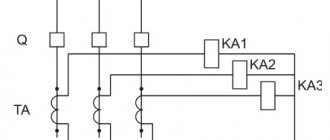
When operating transformers in parallel, the total load on the transformer substation must provide sufficient load to each of them, as judged by the evidence of the corresponding ammeters, the installation of which is mandatory for transformers with a rated power of 1000 kVA and above.
Modern transformers operating at high magnetic induction should not be in operation with a significant increase in the primary voltage, because this is accompanied by an increase in the loss of electronic energy due to heating of the magnetic circuits. A long increase in the primary voltage when the transformer load is not higher than the rated one is allowed up to 5% of the voltage of this branch, and when it is loaded at 25% of the rated power - up to 10%, which can be allowed at a load not higher than the rated duration for up to 6 hours per day.
The degree of load unevenness across the transformer phases should not exceed 20%. It is defined like this:
Kn = (Imax - Iav / Iav) x 100,
where, Imax is the current of the overloaded phase at the moment of greater load on the transformer, Iav is the average current of the 3 phases of the transformer at the same moment.
Electrician school
The influence of loads on the operation of an oil transformer
If the maximum temperature of a winding turn and environmental parameters are taken into account, then systematic loads on an oil-type transformer do not lead to its wear or failure. Taking into account the graphs created by specialists, you can correlate the necessary values and select the load level that corresponds to stable and uninterrupted operation.
The normal service life will not decrease, since the insulation does not wear out. An oil-type transformer will last at least twenty years.
The main problem is that it is not so easy for a novice specialist to determine on his own using graphs or flowcharts the required degree of load. Therefore, to get started, choose models from modern manufacturers with clear operating sheets. They prescribe design indicators, indicate not only the load parameters under different modes, but also provide independent calculation schemes.
Emergency overloads lead to wear and tear of the insulation. As a result, the transformer windings become unusable. Breakdowns occur within them or at the boundaries of the transformer structure and windings. Electric current cannot flow uninterruptedly and short circuits are possible. The service life specified by the manufacturer is reduced many times over.
Methods are used to compensate for insulation wear (when operating at reduced load parameters), but this does not always lead to positive expected results.