Overload of power transformers (long-term permissible and short-term emergency)
Overload of power transformers is an important parameter required both in the design and operation of power plants and substations
The article presents current regulatory documents on the basis of which permissible overloads of transformers are determined
Permissible long-term overload of power transformers according to PTE
| Type of transformers | Long-term permissible overload* |
| Oily | 5%** [p. 5.3.14 PTE ESS], [p. 2.1.20 PTEP] |
| With liquid non-flammable dielectric | 5%** [p. 2.1.20 PTEP] |
| Dry*** | are installed by factory instructions [5.3.15 PTE ESS] |
Notes:
* — long-term permissible means an arbitrarily long duration of overload;
** - the overload is indicated as a % of the rated current of the branch (if the voltage on the branch does not exceed the rated one)
*** - in practice, dry transformers are tried not to overload;
In addition, for transformers, depending on the operating mode, systematic overloads are allowed, the value and duration of which are regulated by the standard operating instructions for transformers and the manufacturers' instructions [p. 5.3.14 PTE ESS], [p. 2.1.20 PTEP].
Emergency short-term overload of a transformer according to PTE
In emergency modes, short-term overload of transformers in excess of the rated current is allowed for all cooling systems, regardless of the duration and value of the previous load and the temperature of the cooling medium within the following limits [5.3.15 PTE ESiS], [p. 2.1.20 PTE P]:
| Oil transformers | |||||
| Overcurrent,% | 30 | 45 | 60 | 75 | 100 |
| Overload duration, min | 120 | 80 | 45 | 20 | 10 |
| Dry transformers | |||||
| Overcurrent,% | 20 | 30 | 40 | 50 | 60 |
| Overload duration, min | 60 | 45 | 32 | 18 | 5 |
Emergency short-term overload of a transformer according to Order of the Ministry of Energy of the Russian Federation N250 dated May 6, 2014.
In accordance with Appendix No. 1 “Guidelines for determining the degree of load of electric grid facilities commissioned after construction” (approved by Order of the Ministry of Energy of the Russian Federation N250 dated 05/06/2014):
Permissible emergency overloads for power (auto-) transformers of various cooling systems depending on the temperature (°C) of the cooling medium (in fractions of the rated current)
| Temperature (°C) of the cooling medium | Cooling system | |
| M, D | DC, C | |
| For transformers with a service life of less than 30 years | ||
| -20°C and below | 1,5 | 1,5 |
| -10°С | 1,5 | 1,4 |
| 0°C | 1,4 | 1,4 |
| 10°C | 1,3 | 1,3 |
| 20°C | 1,3 | 1,2 |
| 30°С | 1,2 | 1,2 |
| 40°C | 1,1 | 1,1 |
| For transformers with a service life of more than 30 years | ||
| -20°C and below | 1,2 | |
| -10°С | 1,2 | |
| 0°C | 1,15 | |
| 10°C | 1,0 | |
| 20°C | 1,0 | |
| 30°С | 1,0 | |
| 40°C | 1,0 | |
Emergency short-term overload of a transformer according to GOST 14209-97 (simplified tables)
Permissible emergency overloads without taking into account the previous load (according to GOST 14209-97, Table N.1)
| Cont. overloads during the day, h | Overload as a fraction of the rated current, depending on the temperature of the cooling medium during overload | |||
| -25°С | ONAN | ON | OF | O.D. |
| 0,5 | 2,0 | 1,8 | 1,6 | 1,4 |
| 1,0 | 1,9 | 1,7 | 1,6 | 1,4 |
| 2,0 | 1,9 | 1,7 | 1,5 | 1,4 |
| 4,0 | 1,8 | 1,6 | 1,5 | 1,4 |
| 8,0 | 1,7 | 1,6 | 1,5 | 1,4 |
| 24,0 | 1,7 | 1,6 | 1,5 | 1,4 |
| -20°C | ONAN | ON | OF | O.D. |
| 0,5 | 1,9 | 1,7 | 1,6 | 1,5 |
| 1,0 | 1,9 | 1,6 | 1,5 | 1,4 |
| 2,0 | 1,8 | 1,6 | 1,5 | 1,4 |
| 4,0 | 1,7 | 1,6 | 1,5 | 1,4 |
| 8,0 | 1,7 | 1,5 | 1,5 | 1,4 |
| 24,0 | 1,6 | 1,5 | 1,5 | 1,4 |
| -10°C | ONAN | ON | OF | O.D. |
| 0,5 | 1,7 | 1,6 | 1,5 | 1,4 |
| 1,0 | 1,7 | 1,5 | 1,5 | 1,4 |
| 2,0 | 1,7 | 1,5 | 1,5 | 1,3 |
| 4,0 | 1,6 | 1,5 | 1,4 | 1,3 |
| 8,0 | 1,6 | 1,5 | 1,4 | 1,3 |
| 24,0 | 1,6 | 1,5 | 1,4 | 1,3 |
| 0°C | ONAN | ON | OF | O.D. |
| 0,5 | 1,7 | 1,5 | 1,4 | 1,3 |
| 1,0 | 1,7 | 1,5 | 1,4 | 1,3 |
| 2,0 | 1,6 | 1,5 | 1,4 | 1,3 |
| 4,0 | 1,6 | 1,4 | 1,4 | 1,3 |
| 8,0 | 1,6 | 1,4 | 1,4 | 1,3 |
| 24,0 | 1,5 | 1,4 | 1,4 | 1,3 |
| 10°C | ONAN | ON | OF | O.D. |
| 0,5 | 1,7 | 1,4 | 1,4 | 1,3 |
| 1,0 | 1,6 | 1,4 | 1,4 | 1,3 |
| 2,0 | 1,5 | 1,4 | 1,3 | 1,2 |
| 4,0 | 1,5 | 1,3 | 1,3 | 1,2 |
| 8,0 | 1,5 | 1,3 | 1,3 | 1,2 |
| 24,0 | 1,5 | 1,3 | 1,3 | 1,2 |
| 20°C | ONAN | ON | OF | O.D. |
| 0,5 | 1,5 | 1,3 | 1,3 | 1,2 |
| 1,0 | 1,4 | 1,3 | 1,3 | 1,2 |
| 2,0 | 1,4 | 1,3 | 1,3 | 1,2 |
| 4,0 | 1,4 | 1,3 | 1,2 | 1,2 |
| 8,0 | 1,4 | 1.3 | 1,2 | 1,2 |
| 24,0 | 1,4 | 1,3 | 1,2 | 1,2 |
| 30°C | ONAN | ON | OF | O.D. |
| 0,5 | 1,4 | 1,2 | 1,2 | 1,2 |
| 1,0 | 1,3 | 1,2 | 1,2 | 1,2 |
| 2,0 | 1,3 | 1,2 | 1,2 | 1,2 |
| 4,0 | 1,3 | 1,2 | 1,2 | 1,1 |
| 8,0 | 1,3 | 1,2 | 1,2 | 1,1 |
| 24,0 | 1,3 | 1,2 | 1,2 | 1,1 |
| 40°C | ONAN | ON | OF | O.D. |
| 0,5 | 1,3 | 1,2 | 1,2 | 1,2 |
| 1,0 | 1,3 | 1,2 | 1,2 | 1,1 |
| 2,0 | 1,3 | 1,2 | 1,1 | 1,1 |
| 4,0 | 1,2 | 1,2 | 1,1 | 1,1 |
| 8,0 | 1,2 | 1,1 | 1,1 | 1,1 |
| 24,0 | 1,2 | 1,1 | 1,1 | 1,1 |
Permissible emergency overloads without taking into account the previous load, not exceeding 0.8 rated current (according to GOST 14209-97, Table N.2)
| Cont. overloads during the day, h | Overload as a fraction of the rated current, depending on the temperature of the cooling medium during overload | |||
| -25°С | ONAN | ON | OF | O.D. |
| 0,5 | 2,0 | 2,0 | 1,9 | 1,7 |
| 1,0 | 2,0 | 2,0 | 1,7 | 1,6 |
| 2,0 | 2,0 | 1,9 | 1,7 | 1,5 |
| 4,0 | 1,9 | 1,7 | 1,6 | 1,5 |
| 8,0 | 1,7 | 1,6 | 1,6 | 1,4 |
| 24,0 | 1,7 | 1,5 | 1,6 | 1,4 |
| -20°C | ONAN | ON | OF | O.D. |
| 0,5 | 2,0 | 2,0 | 1,8 | 1,6 |
| 1,0 | 2,0 | 2,0 | 1,7 | 1,5 |
| 2,0 | 2,0 | 1,9 | 1,6 | 1,4 |
| 4,0 | 1,8 | 1,6 | 1,5 | 1,4 |
| 8,0 | 1,7 | 1,5 | 1,5 | 1,4 |
| 24,0 | 1,7 | 1,5 | 1,5 | 1,4 |
| -10°C | ONAN | ON | OF | O.D. |
| 0,5 | 2,0 | 2,0 | 1,7 | 1,6 |
| 1,0 | 2,0 | 1,9 | 1,6 | 1,5 |
| 2,0 | 1,9 | 1,8 | 1,5 | 1,4 |
| 4,0 | 1,7 | 1,6 | 1,5 | 1,3 |
| 8,0 | 1,6 | 1,5 | 1,4 | 1,3- |
| 24,0 | 1,5 | 1,5 | 1,4 | 1,3 |
| 0°C | ONAN | ON | OF | O.D. |
| 0,5 | 2,0 | 2,0 | 1.7OF | 1,5 |
| 1,0 | 2,0 | 1,8 | 1,6 | 1,4 |
| 2,0 | 1,9 | 1,7 | 1,5 | 1,3 |
| 4,0 | 1,7 | 1,5 | 1,4 | 1,3 |
| 8,0 | 1,6 | 1,4 | 1,4 | 1,3 |
| 24,0 | 1,5 | 1,4 | 1,4 | 1,3 |
| 10°C | ONAN | ON | OF | O.D. |
| 0,5 | 2,0 | 1,9 | 1,6 | 1,5 |
| 1,0 | 1,9 | 1,7 | 1,5 | 1,4 |
| 2,0 | 1,8 | 1,5 | 1,4 | 1,3 |
| 4,0 | 1,6 | 1,4 | 1,3 | 1,2 |
| 8,0 | 1,5 | 1,3 | 1,3 | 1,2 |
| 24,0 | 1,5 | 1,3 | 1,3 | 1,2 |
| 20°C | ONAN | ON | OF | O.D. |
| 0,5 | 2,0 | 1,8 | 1,5 | 1,4 |
| 1,0 | 1,8 | 1,6 | 1,4 | 1,3 |
| 2,0 | 1,7 | 1,5 | 1,3 | 1,2 |
| 4,0 | 1,5 | 1,3 | 1,3 | 1 ,2 |
| 8,0 | 1,4 | 1,3 | 1,3 | 1,2 |
| 24,0 | 1,4 | 1,3 | 1,3 | 1,2 |
| 30°C | ONAN | ON | OF | O.D. |
| 0,5 | 1,9 | 1,7 | 1,4 | 1,3 |
| 1,0 | 1,8 | 1,5 | 1,3 | 1,3 |
| 2,0 | 1,6 | 1,4 | 1,2 | 1.2 |
| 4,0 | 1,4 | 1,3 | 1,2 | 1,1 |
| 8,0 | 1,3 | 1,2 | 1,2 | 1,1 |
| 24,0 | 1,2 | 1,2 | 1,2 | 1,1 |
| 40°C | ONAN | ON | OF | O.D. |
| 0,5 | 1,8 | 1,6 | 1,3 | 1,3 |
| 1,0 | 1,7 | 1,4 | 1,3 | 1,2 |
| 2,0 | 1,5 | 1,3 | 1,2 | 1,1 |
| 4,0 | 1,3 | 1,2 | 1,1 | 1,1 |
| 8,0 | 1,2 | 1,1 | 1,1 | 1,1 |
| 24,0 | 1,2 | 1,1 | 1,1 | 1,1 |
Transformer cooling system
| Designation | Name |
| D (ONAF) | oil cooling with blast and natural oil circulation |
| M (ONAN) | natural oil cooling |
| DC (OFAF) | oil cooling with blast and forced oil circulation |
| C (OFWF) | oil-water cooling with forced oil circulation |
| ON | denotes cooling types ONAN or ONAF |
| OF | denotes cooling types OFAF or OFWF |
List of normative and technical documentation on the issue of transformer overload
— “Rules for the technical operation of power plants and networks of the Russian Federation”, approved. by order of the Ministry of Energy of the Russian Federation dated June 19, 2003 N 229 (PTE ESS)
— “Rules for technical operation of consumer electrical installations”, approved. by order of the Ministry of Energy of the Russian Federation dated January 13, 2003 N 6 (PTE P)
— “Guidelines for determining the degree of load of electric grid facilities commissioned after construction, as well as for determining and applying coefficients for combining the maximum consumption of electrical energy (power) when determining the degree of load of such objects,” approved. by order of the Ministry of Energy of the Russian Federation dated May 6, 2014 N 250.
— GOST 14209-97 “Guidelines for the loading of power oil transformers”, put into effect as the State Standard of the Russian Federation from 01/01/2002
— STO 56947007-29.180.01.116-2012 “Operating instructions for transformers”, approved. by order of JSC FGC UES dated March 2, 2012 No. 113
— Draft standard “Requirements for the overload capacity of transformers and autotransformers installed at electric power facilities and its maintenance” (prepared by the Ministry of Energy of Russia on July 23, 2018)
It is known that modern dry power transformers are reliable and easy to operate, and do not require additional maintenance costs.Their features are as follows:
- absolutely safe in terms of fire and environmental hazards, so they can be used where increased safety is required, for example in public places, in the subway, in residential buildings, etc.;
- can be installed where there are increased requirements for ecology and environmental protection, for example in resort areas or at water intake stations;
- at industrial enterprises, the installation of dry transformers will eliminate additional costs for the construction of substations and distribution buses and low voltage cables.
There are various series of dry-type transformers.
- Transformers of the TSZGL series are dry power transformers with geofol cast insulation, step-down three-phase two-winding, general purpose, normal design, power from 160 to 2500 kVA, voltage 6, 10, 20 kV. Designed to convert electrical energy in three-phase alternating current power networks with a frequency of 50 Hz. They are installed in industrial premises and public buildings, which are subject to increased requirements in terms of fire safety, explosion protection, and environmental cleanliness. The housings have a degree of protection IP 20.
- Transformers of the TSZN series are dry, with a power from 25 to 1600 kV∙A, with Nomex insulation, voltage up to 10 kV, used in many sectors of the national economy. Designed to convert electrical energy in three-phase alternating current power networks with a frequency of 50 Hz. They can be installed in industrial premises and public buildings, which are subject to increased requirements in terms of fire safety and environmental cleanliness. The most convenient model of explosion-proof casing to maintain. Additional equipment is provided with bus bridges on the YOU and LV sides. With the housing it has a degree of protection IP20.
- Transformers of the TSL series are dry-type, with a power from 25 to 2500 kVA, voltage 6,10 and 20 kV, designed specifically for installation in built-in substations. They are characterized by reduced dimensions, reduced noise levels and minimal operating costs. Fireproof (fire-resistant, self-extinguishing resin is used as a dielectric), environmentally friendly (do not emit harmful substances during a fire, there is no problem of oil release), resistant to dust, moisture and mold.
According to experts, dry transformers with cast resin windings will be used in the future at higher voltage levels, 35 kV. Dry transformers with open windings impregnated under vacuum with polyester resins, in which partial discharges do not occur due to the low mass and thickness of the insulation, will be more in demand for voltages of 6 and 10 kV than other types of dry transformers. The advantages of dry-type transformers are provided not only by new insulating materials, but also by new design principles and manufacturing technologies.
Modern dry-type transformers are characterized by fairly high reliability in operation, but, like other electrical equipment, their service life is influenced by external factors.
Dry-type transformers are susceptible to various chemical and physical factors depending on the quality of the environment. Potential hazards include moisture, physical and chemical contaminants, and wind. During storage, the temperature of the transformer is equal to the ambient temperature. During this period, its insulation is exposed to moisture: penetration into the insulation and condensation on the surface, which can cause discharges (“overlaps”) when voltage is applied. For this reason, it is recommended to store the transformer at a relative air humidity of no higher than 90%, and before putting it into operation, make sure there is no condensation. During operation, dry-type transformers can be exposed to various influences. Although the operating temperature of the windings is higher than ambient temperature, high humidity can cause moisture to penetrate into the winding material and degrade the insulating properties.
It is known that electrostatic fields attract dust particles settling on the surface of high voltage windings. This reduces the resistance to surface leakage currents, increasing the likelihood of transformer insulation flashovers [1]. Hydrocarbon vapors attracted by electrostatic fields can be deposited on the surface of the windings.
Subsequently, under the influence of temperature, hydrocarbons can transform chemically, forming semiconductive or conductive deposits, which can contribute to the flashover of insulation or impair the distribution of the electric field over the surface, promoting the accumulation of conductive dust. In addition to the influence of electrostatic fields, there is corrosion of insulating materials, the rate of which depends on humidity and temperature, and degradation of dielectric properties. The degree of influence of dust, sand and salt depends on the wind speed.
In this case, the following situations are possible:
- deterioration of electrical parameters: quality of contacts, resistance to leakage currents;
- obstruction of fans;
- abrasive effect on the surface of insulators and a decrease in surface resistance;
- accumulation of conductive dust on HV windings;
- clogged ventilation holes.
Since fine dust is hygroscopic, this contributes to the formation of a conductive layer on the surface of the insulator.
For dry transformers operating within a city with industrial facilities or heavy traffic, as well as in dust-unprotected areas (except for those close to dust sources), the following restrictions must be taken into account:
- relative air humidity – no more than 90%;
- S02 concentration – no more than 0.1 mg/m3;
- NOx concentration – no more than 0.1 mg/m3;
- concentration of dust and sand – no more than 0.2 mg/m3;
- concentration of sea salt – no more than 0.3 g/m3.
Recommendations are given in accordance with IEC 60721.
Taking into account these limitations preserves the service life of dry-type transformers for decades.
The thermal operating conditions of a transformer are one of the most important factors affecting the aging of insulation and, as a consequence, its service life.
The following are conditions that are recommended to be met to ensure the required cooling, regardless of the size of the room and the degree of protection of the dry-type transformer (presence of an enclosure).
These recommendations also apply to other types of electrical equipment.
The large volume of space above the transformer promotes better outflow of heated air. In addition, the effectiveness of ventilation depends on its ability to remove air from the upper part of the room. To do this, the supply opening should be located as low as possible, and the exhaust opening should be as high as possible and on the opposite side.
The location of the supply vent (a blow-in fan) above the transformer prevents hot air from escaping from it. This can lead to an increase in the temperature of the transformer above the permissible limit. In the best case, thermal protection will work; at worst, if it is missing, overheating and premature aging of the insulation will occur.
It is known that the purpose of ventilation is to reduce the heat generated by electrical equipment (transformers, motors, heaters, etc.).
In normal mode, the equipment emits power losses P (kW), for removal of which using ventilation it is necessary that there be:
- cold air inlet opening with effective area S (m2), located below near the transformer (the effective area of the opening is its real area, minus all interference - grilles, valves, etc.);
- hot air exhaust hole with effective area S' (m2), located at the top on the opposite side, if possible above the transformer, at a height H (m) relative to the lower hole [1].
The area of the holes can be determined by the formulas: S = (0.18P)/N; S' = 1.1∙S.
These formulas are applicable when installing equipment at an altitude of up to 1000 m above sea level at an average annual temperature of 20 °C.
If it is impossible to provide the above opening areas for natural ventilation of the room, forced ventilation should be used using the installation:
- at the lower hole - a supply fan with a capacity of Q (m3/s), determined by the power loss according to the formula: Q' = 0.1∙Р;
- at the top hole - exhaust fan = 0.11∙R.
If the area of only one of the holes is insufficient, it can be limited to installing the fan only on it. The space above the transformer must remain free up to the ceiling, with the exception of connections.
It should be remembered that the accumulation of dust on the transformer interferes with normal heat dissipation. This is especially true for dusty industries. It is necessary to carry out regular cleaning using a vacuum cleaner (not blowing!).
From the point of view of ventilation of the transformer and the possibility of its overheating, air humidity is not a dangerous factor. However, the presence of heating elements that prevent the formation of condensation should be taken into account when calculating the dimensions of the room and ventilation openings.
Depending on the degree of protection (IP) and the transparency of the mesh on the walls of the casing, the required effective area of the ventilation openings may be quite large. For example, in an IP31 enclosure of a dry-type transformer, the grid perforation area is about 50%. If a dry-type transformer is used in violation of the permissible conditions prescribed for its storage, commissioning and operation itself, then its service life will be reduced.
If other equipment is installed in the room, when calculating ventilation, power P must include its losses at full load.
CONCLUSION
Dry transformers can be used in moderately cold climates, as well as in rooms where climatic conditions are controlled artificially. For normal operation of dry power transformers, it is necessary to maintain a temperature from +1 °C to +35 °C. In addition, they require a non-explosive environment, which must contain dust and other impurities no more than the permissible limit. Dry-type transformers are not designed to operate in adverse conditions, in particular in conditions of shaking, vibration, shock, or in an environment that is chemically active. In addition, dry transformers can only be used at altitudes up to 1000 m above sea level.
Dry transformers are produced by many companies both in the Russian Federation and abroad. Below, as an example, is general information about dry-type power transformers produced by some well-known companies.
The RosEnergoTrans enterprise produces the following dry transformers:
- with cast insulation with a capacity from 25 to 16 thousand kV∙A for voltage classes up to 35 kV;
- with air-barrier insulation with a power from 25 to 12,500 kV∙A for voltage classes up to 35 kV.
These are transformers of the TS and TSZ series, which can replace previously installed oil, sovtol, dry transformers of the series: TSGL, TSZGL, TSZGLF, GDNN, GEAFOL, SGB, RESIBLOC, TRIHAL, TTA-RES and others without additional costs.
produces the following types of dry transformers:
- general purpose power distribution systems;
- converters for powering DC electric drives in metallurgical, drilling, oil and gas production and other industries;
- dry for conversion installations of urban transport (metro, tram, trolleybus);
- dry for the own needs of power plants and other facilities.
Bratislava Electrotechnical Plant BEZ TRANSFORMATORY, as produces the following dry-type transformers:
- with cast insulation of the aTSE series with aluminum windings and natural air cooling. Transformer power range – from 63 to 4000 kV∙A, rated voltage 6,10,20 and 35 kV;
- with cast insulation, copper windings and natural air cooling. The range of transformer capacities is from 630 to 3150 kV∙A, rated voltage 6, 10, 20 and 35 kV.
Dry transformers aTSE and TSE are analogs of dry transformers TSL, TSGL, TSZL.
produces commercially dry three-phase transformers with natural air cooling of the TS and TSZ type with Nomex insulation, which are used to convert electricity in alternating current networks with a frequency of 50 Hz.
Dry transformers provide the possibility of five-stage voltage regulation (PBV type) with a regulation range of ±2 × 2.5% of the rated voltage on the 6 (10) kV side.
The main insulating materials (main and longitudinal insulation) for TS and TSZ transformers are paper and cardboard made of aromatic polyamide, manufactured on the basis of special Nomex technology developed by .
LV winding type – layer, material – copper or aluminum foil. The type of HV winding is continuous coil, the material is rectangular copper or aluminum wire. The heat resistance class of transformers such as TS and TSZ is N (180 °C), but taking into account the fact that the heat resistance of Nomex insulation is 220 °C, the transformers will have a high load capacity.
Nomex insulation and varnish application using a pressure vacuum impregnation process combined with heat curing make the winding resistant to dust, moisture and contaminants.
The selected types of windings and type of materials for transformers of the TS and TSZ series, namely ONN - layer (material - copper or aluminum foil), and OVN - continuous coil (material - rectangular copper or aluminum wire) have a number of advantages over other types of windings:
- high resistance to dynamic shocks from short circuit currents;
- high electrical strength;
- good heat dissipation.
The TS and TSZ series of power transformers have high electrical and mechanical characteristics, including the ability to withstand mechanical stresses caused by sudden and wide temperature changes.
TS transformers are manufactured with protection degree IP00 (without casing). TSZ transformers are manufactured with a degree of protection IP21 (in a casing). Transformers are used in the construction of cottages, small industries, urban neighborhoods, as well as large industrial enterprises and power distribution facilities.
The company produces dry transformers with non-standard power, with increased short-circuit voltage (up to 8–12%), with reduced losses (with copper windings), with split secondary winding (including for outdoor installations), etc. The most commonly produced capacities dry transformers with Nomex insulation: 630, 1000, 1600, 2000, 2500 kV A (6 and 10 kV).
Schneider Electric manufactures Trihal series dry-type transformers with cast epoxy insulation cast under high vacuum. Transformers are designed for distribution electrical networks with voltages of 6,10 and 20 kV.
Trihal series transformers have exceptional fire protection properties due to the addition of aluminum trihydrate to the epoxy casting. In the event of fire, the additive ensures the formation of aluminum oxide, which creates a fireproof reflective layer and a “jacket” of water vapor around the winding, as well as intensive heat removal from the winding.
Table 1. Technical characteristics of Trihal series transformers
Rated power, kVA
| 160 | 250 | 400 | 630 | 1000 | 1250 | 1600 | 2000 | 2500 | |
| Rated voltage of the HV winding, kV | 6, 10 | ||||||||
| Rated voltage of the LV winding, kV | 0,4 | ||||||||
| Method and range of regulation | PBB; +2 × 2.5% | ||||||||
| Losses XX, kW | 0,61 | 0,82 | 1,0 | 1,37 | 2,0 | 2,5 | 2,8 | 3,5 | 4,3 |
| Load loss at 75 °C, kW | 2,3 | 3,1 | 4,5 | 6,7 | 8,8 | 10,5 | 12,3 | 14,9 | 18,3 |
| Load losses at 120 °C, kW | 2,7 | 3,5 | 5,2 | 7,6 | 10,0 | 12,0 | 14,0 | 17,0 | 21,0 |
| Short-circuit voltage, % | 6 | 6 | 6 | 6 | 6 | 6 | 6 | 6 | 6 |
| Operating temperature range, °C | -25… +45 | ||||||||
As a result of these factors, the temperature of the windings never reaches the flash point of the insulation and immediate self-extinguishing occurs. The transformer has a low level of partial discharges thanks to a special winding technology and filling in a deep vacuum, and each commercially produced transformer simultaneously meets the requirements for: fire resistance class (F1); by environmental influences (frequent condensation and severe pollution - E2); on climate impacts (C2).
In table 1 shows the technical characteristics of dry transformers of the Trihal series.
In table 2 shows the weight and size parameters of dry transformers of the Trihal series.
Table 2. Weight and dimensions parameters of dry transformers of the Trihal series
| Rated power (kV∙A) | 160 | 250 | 400 | 630 | 1000 | 1250 | 1600 | 2000 | 2500 |
| Dimensions, mm: | |||||||||
| Length | 990 | 1070 | 1295 | 1395 | 1490 | 1515 | 1605 | 1680 | 1830 |
| Width | 665 | 680 | 795 | 810 | 945 | 945 | 945 | 1195 | 1195 |
| Height | 1330 | 1370 | 1335 | 1520 | 1660 | 1810 | 1880 | 2105 | 2200 |
| Weight, kg | 770 | 950 | 1230 | 1660 | 2200 | 2510 | 2980 | 3600 | 4730 |
GENERAL ELECTRICAL CHARACTERISTICS OF DRY TRANSFORMERS OF THE TRIHAL SERIES
- Maximum installation height 1000 m;
- heat resistance class F (heating 100 °C);
- diagram and connection group of windings ∆/Y0–11 or ∆/Y0–5;
- partial discharge level at 1.3 Unom<10 pC.
One of the important parameters when operating dry power transformers is their overload. Basically, all manufacturers of dry-type power transformers test them for overload capacity, but not all manufacturers provide the overload value of these transformers in their technical characteristics. The latter makes it difficult for operators to correctly select the operating mode of a dry-type transformer at different loads, especially during forced overload.
For example, in the technical specifications for dry transformers TSGL/aTSE, produced within the framework of a joint project between Russian companies, MOSENERGO OJSC and the Slovak company BEZ TRANSFORMATORY, as, the permissible overload is given, which is 1.5. However, the duration of operation of a dry-type transformer under such an overload is not indicated.
At the same time, the following operating conditions for dry transformers TSGL/aTSE are given:
- the height of their installation above sea level should not exceed 1000 m;
- The ambient temperature can be in the range from -45 °C to +40 °C, if the average daily temperature does not exceed +30 °C, and the average annual temperature – +20 °C. Dry-type power transformers are cooled by natural air circulation (AN) and must therefore be installed in such a way that they are effectively cooled during operation.
Against overheating, the transformers are protected by thermal posistor protection built into the low-voltage winding and connected to the thermal relay terminals with a supply voltage of 220 V AC, 110 V or 220 V DC. Thermal protection has two cascades. The first stage is a signaling stage, and the second is set to the highest temperature limit. On request, the transformers are also supplied with thermal protection using Pt 100 resistance thermometers.
SCHNEIDER ELECTRIC, in the technical specifications for dry power transformers of the TRIHAL series, indicates that overloading of transformers without reducing service life is permitted, provided that they are compensated by a working load less than the rated power.
A transformer designed to operate at an ambient temperature of 40 °C can be used at higher temperatures with a reduction in power as shown below:
| Maximum ambient temperature | Permissible load |
| 40 °C | R |
| 45 °C | 0.97R |
| 50 °C | 0.94R |
| 55 °C | 0.90R |
The rated power is determined by natural air cooling (AN-air natural).
A power overload of 40% is possible with forced cooling of the transformer (AF - forced air cooling).
The “Basic Rules for Ensuring the Operation of Nuclear Power Plants” (3rd edition, amended and supplemented, RD EO 0348-02) in section 14.3.16 states that in emergency modes, short-term overload of transformers in excess of the rated current is allowed for all cooling systems, regardless of the duration and values of previous load and ambient temperature within the following limits for dry transformers:
| Overcurrent,% | 20 | 30 | 40 | 50 | 60 |
| Overload duration, min | 60 | 45 | 32 | 18 | 5 |
GOST R 54419-2011 “Power transformers. Part 12: Guidance on Dry Transformer Loading" Section 4 provides a general approach to overloading, namely: it states that there are consequences of overloading a transformer beyond its rated parameters, the consequences and risks of a short-term emergency overload, as well as the results of a long-term emergency overload.
An analysis of directive materials on overloads of power dry transformers shows that these documents provide mainly general information about overloads and recommendations on them.
Specific values of emergency and long-term overloads must be requested from the manufacturers of those dry power transformers that the designer uses in his projects and will subsequently be used by the operator.
This approach will ensure the warranty period for the dry transformer that the manufacturer specifies for this equipment.
BIBLIOGRAPHICAL LIST
- Website https://forsa.ru/ssylki-po-electroe-nergetike/ [Electronic resource].
- Complete reference book on electrical equipment and electrical engineering (with examples of calculations): reference publication / E.A. Kireeva. – M.: KNORUS, 2012. – 864 p.
ads
Spider Web wrote: 2019-04-24 15:15:13
And what I liked about everything about it, specifically and clearly, when to put AOPO on Tr. or ATr.,
Take your time! Everything is much more fun and interesting than you think. I didn’t see in the document that the transformer should be turned off when either overload or temperature is exceeded. The concept “overload is not allowed” does not mean that the equipment should be turned off. Today, even without these tables, there is overload protection on transformers, but it does not always effect a shutdown. I see these tables as changing the overload protection on transformers to digital protection with discrete settings up to 24 hours, with temperature control, with control of the current transmitted to the system operator, with service life counting, etc. I see problems if, during the day, the operating mode was first with excess temperature, then with current, on a transformer that had not yet cooled down. I don’t see who should press the “red button” to turn it off))). After all, after a shutdown, an investigation is underway and someone will have to answer either for disconnecting consumers (manually or automatically disconnected), or for damage to equipment, or for failure to process requests for possible overload of the transformer. And there have been recent cases in my memory when the deputy chief dispatcher for regimes, rushing to the dacha, did not process the requests and simply resolved them. Those who came to replace the dispatcher, they were calculated on the model, they called the deputy chief dispatcher, saying that the regime did not work, and he, in turn, answered them from the dacha that, if anything happens, then I will take everything upon myself. When there was a blackout, “I’ll take everything upon myself” turned into a plan to kill my subordinates because they didn’t convince the summer resident. And these are not isolated cases - only individuals showed negligence, but survived from groups of people who were not at all involved in this. With new algorithms in which the proposed tables will be based, it will become increasingly more difficult. Yes, AOPT can be installed, but it is not the design institute that decides whether to turn off the transformer or not. It is probably up to other people to introduce shutdown protection or not. It’s not very clear who they are)))
Added: 2019-05-04 22:20:55
Spider Web wrote: 2019-04-24 15:15:13
And what I liked about everything about it, specifically and clearly...
How do you look at the following inconsistencies? The PTF EES in paragraph 126 states this: Autotransformers (transformers) allow emergency overload in the amount and duration determined in accordance with the requirements for the overload capacity of transformers and autotransformers installed at electric power facilities and its maintenance, approved by the authorized federal executive body, but not less than 50 percent within 20 minutes .
This Order in tables No. 2, 3, 4, 5, 6, 7 for a time of 20 minutes indicates at some temperatures a load of less than 50%, moreover, even for a time of 10 minutes tables No. 5, 6, 7 indicate an overload of less than 50% at some temperatures.
What to believe and what to focus on?
Permissible current loads can and should be recalculated
Andrey LYANZBERG Deputy Head of the Electrical Modes Department of the Operational and Technological Management Department of PJSC FGC UES, Ph.D. e-mail
Vasily KAPUSTIN Chief expert of the Department of Electrical Modes of the Department of Operational and Technological Management of PJSC FGC UES e-mail
A. LYANZBERG Deputy Head of the Electric Modes Division of the Department of Operational and Technological Management FGC UES, CES e-mail
V. KAPUSTIN Chief Expert of the Electric Modes Division of the Department of Operational and Technological Management FGC UES e-mail
Annotation. The article discusses the problems associated with outdated requirements for the standardization of permissible current loads of the main electrical equipment of substations and power line wires. The possible positive effect of updating these requirements is described. A description of already implemented solutions in this area is provided. Proposals are given for the development of regulatory requirements taking into account technical limitations. Key words: permissible loads, overhead power lines, substation equipment, regulatory requirements, digitalization.
Abstract. The article discusses the existing problems associated with outdated requirements for the standardization of main substation equipment and overhead lines conductor admissible current capacities. A possible positive effect is described when updating these requirements. A description of already implemented solutions in the power energy area is given. Suggestions for the development of regulatory requirements are given, taking into account engineering constraints. Keywords: admissible capacities, overhead lines, substation equipment, regulatory requirements, digitalization.
The electric power industry is experiencing a stage of active development and implementation of digital technologies in the processes of organizing the receipt, transmission, distribution and conversion of electricity. In the context of the progressive development and implementation of automated digital systems and software systems, it is advisable to consider the possibility of updating and improving regulatory documents regulating, in particular, the requirements for the operation of basic electrical power equipment. The first document that approved the updated approaches was the order of the Ministry of Energy of the Russian Federation “On approval of requirements for the overload capacity of transformers and autotransformers installed at electric power facilities” [1] dated February 2022, in which the overload capacity of transformers and autotransformers depends on a number of factors: technical condition , service life, coolant temperature, duration and magnitude of overload. The article discusses the issue of developing regulatory documents that determine the permissible current loads of overhead power lines and power grid equipment, the updating of which will allow us to take another step towards the digitalization of the industry.
Retrospective, present and future
Currently, the permissible current loads of typical overhead power line wires are regulated by the rules for electrical installations. In this document, permissible current loads on wires are determined under fixed conditions (except for outside air temperature) and are calculated based on the inadmissibility of prolonged heating of overhead line wires above 70 °C. For each value of outside air temperature, the permissible current load of the wires is represented by one number, independent of other factors. Exceeding this value even by a few tenths of a percent is unacceptable both at the design stage and during operation, regardless of the duration of such overload. At the same time, GOST states that the long-term permissible temperature of steel-aluminum wires during operation should not exceed 90 °C. Based on this, we can conclude that it is possible to increase the values of permissible current loads specified in the rules, while ensuring compliance with the requirements in terms of permissible distances from the wire to the ground, obstacles and intersections.
Now it is advisable to consider the possibility of updating standards for the operation of basic electrical power equipment
In addition, the values of permissible current loads on wires are regulated in the rules at outdoor temperatures from –5 to +50 °C, although it is known that the maximum loads in the power system occur in the cold season, when temperatures in many regions of Russia are significantly lower than – 5°C. During these periods, it is possible to increase the permissible current loads, taking into account additional cooling of the wire. They do not take into account the rules and design features of the line, the climatic conditions of the region where it is located, including factors such as solar radiation, wind direction and strength. The air line capacity requirements specified in the rules were developed more than forty years ago. The research available today in the field of transmission capacity of power line wires is sufficient to create mathematical models that allow a detailed analysis of the electrothermal and mechanical processes that affect the heating of the wire, and, as a consequence, its permissible current load. In addition, existing emergency control systems aimed at limiting the overload capacity of overhead lines have the ability to set multiple response stages depending on the magnitude of the current and the duration of its flow, which allows minimizing the volume of control actions and increasing the reliability of power supply to consumers.
High-voltage power lines Source: Zaiets Roman / Depositphotos.com
Now we have the technical ability to set the capacity of overhead line wires not as one independent number, but as a function of a number of factors: the duration and magnitude of the flowing current, climatic and design conditions. Some network companies are already using such approaches. For example, in Rosseti, the determination of permissible current loads on overhead lines is regulated by the organization’s internal standard [4], which makes it possible to determine long-term and emergency permissible current loads taking into account various factors. As a rule, the values calculated using the standard are higher than the values specified in the rules, and individual values of the permissible emergency load, on the contrary, exceed the values specified in the rules by more than 50%. To determine permissible current loads, a software package is used that allows for automated calculations taking into account the requirements of current regulatory and technical documents. Detailed experience in using the standard and the positive effects of its use are described in [5]. Regulation of the permissible throughput of high-frequency suppressors, linear switches, linear disconnectors, cable inserts, current-limiting reactors and other primary equipment of substations is limited mainly by setting standard nominal lines, which also represent one value without taking into account factors affecting the heating of current-carrying parts. An exception is GOST on current transformers [6], which contains the concept of “highest operating primary current” for current transformers with an indication of the possibility of its exceeding. Using this value as an emergency value allows you to increase the throughput of an electrical network element. However, here too, the value of the emergency load itself is only one number, independent of other factors (according to GOST on current transformers - 120% of the maximum operating current). The constant task of the industry to increase the reliability of power supply to consumers and the availability of the possibility of refined modeling of thermal processes are pushing us to update data on the throughput of primary equipment of substations. Based on the data received from manufacturers, it can already be stated that for most electrical network equipment it is possible to operate with a time-limited excess of the rated current without consequences for its technical condition. In this case, there is a dependence of the nominal throughput on the ambient temperature.
Practical advantages of the new approach
The current load of power lines and power grid equipment with a voltage of 110 kV and above is one of the key characteristics of the electrical power regime of the Unified Energy System. The tasks of network companies include correct determination of the permissible level of network current loads for various conditions. The prepared information on the permissible current loads of the equipment is sent to control rooms of network companies for planning and maintaining the electric power regime, as well as to design organizations for the development of schemes and programs for the long-term development of the electric power industry and other documents. Accordingly, the higher the directional values, the smaller the restrictions, both generation and consumers, are possible when maintaining the regime. The expected capital costs for network development to ensure the possibility of transmitting electricity in the future are also reduced. The efficiency of using the main electrical power equipment, and, therefore, the profit of network organizations and stations depends on the permissible current loads. Throughput capacity is one of the factors determining the possibility of technological connection of new consumers and electricity producers, and increasing the capacity of existing ones. Therefore, many network companies are interested in increasing the capacity of existing electrical networks by fully using the capabilities of the equipment, without reducing service life and reliability. On the other hand, it must be remembered that an excessive increase in the throughput of the main equipment will inevitably lead to a deterioration in the technical condition, an increase in the number of repairs, failure to operate and technological violations.
The rules do not take into account the design features of the power line, the climatic conditions of the region where it is located, including such factors as solar radiation, wind direction and strength.
In accordance with the rules for the technological functioning of electrical power systems [7], the characteristics of the busbars and busbars of the switchgear, measuring current transformers and other electrical network elements should not limit the permissible current loads of any power lines connected to the switchgear. Before these rules were put into effect, this principle was applied, but was not mandatory, therefore, in fact, power systems operate lines whose capacity is limited by the permissible current load of substation equipment. A significant period of time will pass before the requirements are fully met, since replacing and modernizing the electrical grid requires large material and time costs. However, even now, taking into account existing operating experience, it can be argued that it is possible to increase the permissible current loads of some elements without replacing them. In the Russian energy system, cases are not uncommon when the permissible current load of network elements is the limiting criterion for the maximum permissible active power flows in controlled sections. In accordance with the rules of reliability of power systems [8], when determining the maximum permissible flows of active power in controlled sections, the following criteria are taken into account: 1) in post-emergency modes after standard disturbances, the current load of power lines and electrical network equipment should not exceed the emergency permissible current load for 20 minutes ; 2) in normal mode, the current load of power lines and electrical network equipment should not exceed the permissible (taking into account the permissible value and duration of the overload). Based on the formulations, the use of increased permissible current loads for the two specified requirements can increase the actual throughput of the controlled sections of power systems. To do this, it is necessary to have data on the possibilities of overloading equipment at substations and power lines for 20 minutes, as well as their correlation with ambient temperature. In the near future, expanded dependences of the permissible current loads of network equipment on the time of overload, its magnitude and weather factors can be found in real application, affecting the reliability of power supply to consumers. For example, including overload parameters in automation will minimize the volume of outages. In this case, the automation will not immediately disconnect the consumer when the rated capacity of the equipment is exceeded, but will withstand a certain time depending on the magnitude of the overload. During this time, the mode can change both naturally (the passage of a load peak) and through operational actions of dispatch personnel not related to limiting consumers.
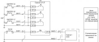
Rice. 1
As a clear example of the advantages of the described approach, let us consider the schematic diagram of an energy district presented in Figure 1. Power supply to consumers is carried out via a 110 kV network from the 220 kV PS-1 substation, on which two 220/110 kV autotransformers with a rated power of 200 MVA are installed. The 220 kV substation PS-1 is powered through the 220 kV overhead line Power System – PS-1 No. 1, No. 2. One of the autotransformers (AT-2) of the supply substation is out for repairs. The values of the permissible current load of the electrical network elements, which can limit the transmission capacity, are presented in Table 1. A possible emergency situation associated with the disconnection of the 220 kV overhead line Power System - PS-1 No. 2 is shown in Figure 2. In post-emergency mode after disconnecting the 220 kV overhead line kV Power system – PS-1 No. 2, AT-1 is loaded at 92% (637 A with a permissible value of 694 A) of the emergency permissible current load at 25 °C, permissible for 20 minutes in accordance with [1]. At the same time, the current transformer at the 220 kV PS-1 substation is loaded at 101% (637 A at the highest operating primary current 630 A).
Table 1. Permissible current load of elements of the electrical network of the energy region under consideration
Rice. 2
In the current circuit-regime situation, in accordance with current standards [9], operation is not permissible. Unacceptable equipment overload must be eliminated immediately by remotely disconnecting consumers to the extent necessary to reduce the current load of electrical network equipment below the emergency permissible value. However, if we take into account the information received from the current transformer manufacturer about the permissibility of overloading above the maximum operating primary current by 20% without a time limit (up to 756 A), then the dispatcher has 20 minutes to load the generating equipment of power plants in the receiving part of the power system, changes in the topology of the electrical network, transfer of load from the receiving part of the power system to adjacent power regions. Thus, the permitted overload of the current transformer will avoid disconnecting the load of consumers. Any equipment connected in series can have a similar effect.
Conclusion
The course of development of the electric power industry taken towards digitalization cannot be limited only to the area of technological processes; in parallel with it, it is necessary to make corresponding rule-making decisions. A logical step in this area could be the regulatory consolidation of an updated procedure for determining the permissible current loads of typical wires of overhead power lines and main substation equipment. This approach will allow: – to reduce the costs of construction and reconstruction of power grid facilities when connecting new consumers; – reduce the number of regime generators, which entails a reduction in the financial burden on end consumers; – reduce the consequences of emergency shutdowns by reducing the volume of the disconnected load; – increase the maximum permissible active power flows in existing controlled sections.