Isolation transformers are those with the same voltage or current characteristics at the output and output. Such devices have the same number of turns on the primary and secondary coils. As a result, the transformation coefficient is equal to unity. The use of such units increases safety, since there are no electrical connections in the secondary circuits with a voltage source or ground.
The separation of the input and output windings is ensured by reinforced double insulation. An additional measure is to place the coils on physically different cores.
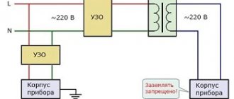
The secondary winding is made without grounding the zero contact, so accidental touching it will not cause an electric shock unless a person simultaneously touches a metal pipe, does not stand in a damp place, or the danger of electric current passing through the body arises in another way.
Principle of operation
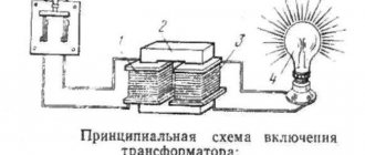
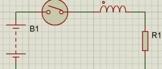
The device operates on a principle similar to a conventional transformer: when current is supplied to the primary coil, a magnetic flux is induced in it, followed by its formation in the secondary winding, which causes the transmission of electric current. Since the characteristics of the coils are identical, the electric current parameters of the primary and secondary windings will be the same.
Isolation transformer circuit
Classification
Currently, several types of isolation transformers are commercially produced, designed for the safe operation of electrical installations. The following types of such devices are distinguished:
- current - the primary coil is used to connect a current source, the secondary is sent to an electric meter or similar device. Installed in a measuring or relay electrical network;
- peak - for converting sinusoidal voltage, in most cases used in digitizing devices;
- pulse type – convert the received signal into a pulse, smooth out high-frequency interference;
- automatic - the design connects the input and output windings together, which forms an electrical connection, together with a magnetic one;
- power ones - with several windings, allowing the characteristics to be transformed simultaneously with transmission;
- portable – used for organizing lighting systems outdoors or indoors.
Also read: KTPN - outdoor complete transformer substation
The devices can provide for highly specialized conditions of use. Such devices are installed in medical institutions to supply power to operating rooms, inpatient departments and other important departments where high safety requirements are imposed.
Isolation transformer
Connections[edit]
Phase to Line Transformer in the UK Primary line to the right towards the front and secondary lines to the rear of this single phase transformer
Both pole and site mounted transformers convert the high "primary" voltage of overhead or underground distribution lines into the lower "secondary" or "service" voltage » tension inside the building. The primary distribution wires use a three-phase system. Main distribution lines always have three "hot" wires plus an additional neutral. In the North American system, where single-phase transformers are connected to only one phase wire, smaller "side" lines branching on side roads may only include one or two "hot" phase wires. (When there is only one phase conductor, the neutral will always be used as the return path.) Primary circuits provide power at the standard distribution voltage used in the area; they range from 2.3 kV to approximately 35 kV depending on local practices and distribution standards; 11 kV (50 Hz systems) and 13.8 kV (60 Hz systems) are often used, but other voltages are also common. For example, in the USA the most common voltage is 12.47 kV. The voltage between phase and neutral is 7.2 kV, which is exactly 30 times greater than the 240 V split-phase secondary side.
Primary[edit]
The primary high voltage windings are brought out to the inputs in the upper part of the housing.
- Single-phase transformers, commonly used in North American systems, are connected to overhead distribution wires using two different types of connections: Star - Star distribution uses a star or phase-to-neutral transformer. A single-phase star transformer usually has only one input at the top, connected to one of the three primary phases. The other end of the primary winding is connected to the transformer body, which is connected to the neutral wire of the star system and is also grounded. A star distribution system is preferred because transformers present unbalanced loads on the lines, which induce currents in the neutral wire and are then grounded. But in a delta distribution system, unbalanced loads can cause voltage fluctuations on the three-phase wires.
- Delta - The delta distribution circuit uses a delta or phase-to-phase transformer. A single-phase delta transformer has two inputs connected to two of the three primary wires, so the primary winding sees phase-to-phase voltage. This avoids the return of the primary current through the neutral, which must be firmly grounded to maintain its voltage close to ground potential. Since neutral is also provided to customers, this is a great safety benefit in dry areas like California where soil conductivity is low. The main disadvantage is the higher cost, for example due to the need for at least two insulated hot phase wires even in a branch circuit. Another smaller disadvantage is that if only one of the primary phases is disconnected upstream, it will remain energized as the transformers try to return current through it. This can be dangerous for line workers.
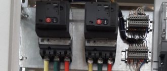
The transformer is always connected to the primary distribution lines through protective fuses and disconnected circuit breakers. For pole-mounted transformers, this is usually the "fuse". If there is an electrical fault, the fuse will melt and the unit will open, providing a visual indication of the fault. It can also be opened manually while the line is fed by linemen using insulated hot sticks. In some cases, completely self-protected transformers are used that have a circuit breaker built into them, so a fuse is not required.
Secondary[edit]
"Transformer bank", commonly used in North America: three single-phase transformers connected to create a three-phase transformer.
The low voltage secondary windings are connected to three or four terminals on the transformer side.
- In homes and small businesses in North America, the secondary winding is most often a 120/240 volt split-phase system. The 240V secondary winding is center tapped and the center neutral wire is grounded, causing the two end conductors to become "hot" relative to the center tap and 180 degrees out of phase with each other. These three wires run down the service line to the electric meter and service panel inside the building. Connecting a load between the hot wire and the neutral produces 120 volts, which is used for lighting circuits. The connection between both hot wires produces 240 volts, which is used for heavy loads such as air conditioners, ovens, dryers, and electric vehicle charging stations.
- In Europe and countries using this system, the secondary is often a 400Y/230 three-phase system. There are three 230V secondary windings, each energized by a primary connected to one of the primary phases. One end of each secondary winding is connected to a "neutral" wire, which is grounded. The other end of the three secondary windings, together with the neutral, is brought out to the service panel. 230 V loads are connected between any of the three phase wires and the neutral. Since the phases are 120 degrees apart, the voltage between any two phases is sqrt(3)*230V = 400V, compared to 2*120V = 240V in the North American split-phase system. While three-phase power is almost unheard of in individual homes in North America, it is common in Europe for heavy loads such as air conditioners and electric vehicle chargers.
Commercial and industrial applications sometimes require higher secondary voltages, such as 480 volts. Some industrial consumers require three-phase power supply with secondary voltage. For this you can use three-phase transformers. In the US, where predominantly single-phase transformers are used, three identical single-phase transformers are often connected to a transformer
using a star or delta circuit to create a three-phase transformer.
Application
The use of isolation transformers is especially necessary in premises whose operation is subject to increased electrical safety requirements. This applies to:
- basements;
- cable wells;
- objects with high humidity levels;
- gas hazardous places;
- when using a power tool of the first electrical safety class.
At home, such devices can be installed in bathrooms, swimming pools and other technical rooms where a higher level of protection against electric shock is required. It is possible to connect them to boiler units.
Purpose
A three-phase or single-phase isolation device is used to minimize risks during the operation of electrical equipment. There are three main areas for which the presented device is used:
Due to the listed qualities, the use of three-phase or single-phase isolation-type transformers is recommended for both domestic and industrial purposes. It can reduce the risk of craftsmen during the operation of electrical equipment. Such units are used in baths, bathtubs, loudspeakers, and other conditions of increased risk of electric shock. In industry, various machines and machines operate on electricity, which is generated by an isolation transformer.
Manufacturers of household appliances recommend installing an RCD before connecting the equipment to the network. This allows you to meet the safety requirements for its operation.
Advantages and disadvantages of the device
The use of isolation transformers allows you to achieve the following advantages:
- increase the service life of electrical appliances;
- reduce the amount of electric current during a short circuit;
- additional protection during operation of electrical equipment;
- improve the quality characteristics of the electrical network;
- filter out high frequency interference.
The disadvantage of these devices is the additional complexity of the home or industrial network and the inability to provide complete protection against electric shock.
Specifications
The industry supplies the market with many models with different characteristics. It is simply impossible to remember them. Yes, this is not necessary. Most of the characteristics will be of interest only to narrow specialists.
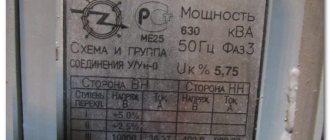
For practical purposes, it is enough to know the basic parameters of the transformer. Typically, these parameters are indicated in the device passport.
When choosing an isolation transformer, pay attention to the following main characteristics:
- rated power;
- current frequency;
- primary stress;
- output (secondary) voltage;
- symbol of the winding connection diagram;
- voltage in short circuit mode;
- heat losses during short circuit;
- no-load current;
- heat losses when operating in idle mode;
- dimensions.
The rated power should be the same as or slightly higher than the load power. The primary voltage must correspond to the parameters of the primary network, and the secondary voltage must correspond to the supply voltage of the connected electrical appliances. When choosing pulse transformers, pay attention to the current frequency.
Characteristics in italics are important, but understanding them requires a more advanced knowledge of electrical engineering.
How to make your own isolation transformer
It is not difficult to make a low-power device yourself, if you have similar skills and basic knowledge in the field of electrical engineering.
Sequence of operations:
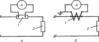
- two half windings are made on two identical cores - the coils are divided in half;
- a pair of half windings are connected in series;
- Additionally, you can equip the device with a throttle or stabilizer.
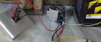
A more detailed diagram of the device and the order of connecting the half-windings is shown in the diagram:
The device can be used to power a workshop or other auxiliary room. Before connecting to a stationary power supply, the device must be tested with a small electric current. An ordinary low-power lamp is suitable as a consuming device.
But if the home handyman does not have enough electrical knowledge and no experience in such work, it is recommended to contact a specialist of the appropriate profile.
Links[edit]
- Jump up
↑ Harlow 2012, p. 3-4. - Jump up
↑ Bakshi 2009, p. 1-24. - Jump up
↑ Bakshi 2009, p. 1-25. - ^ a b
Harlow 2012, pp. 3-17. - Jump up
↑ Harlow 2012, p. 3-10. - De Keulenaer et al. 2001 harvnb error: no target: CITEREFDe_KeulenaerChapmanFassbinderMcDermott2001 (help)
- Kubo, T.; Sachs, H.; Nadel, S. (2001). Opportunities for introducing new efficiency standards for household appliances and equipment
. American Council for an Energy Efficient Economy. item 39, fig. 1 . Retrieved June 21, 2009. - Jump up
↑ Harlow 2012, p. 3-3. - Jump up
↑ Harlow 2012, p. 3-5. - Pansini 2005, p. 63.
- Pansini 2005, p. 61.
- Jump up
↑ Harlow 2012, p. 3-9.