The unpretentiousness and relative physical stability of posistors allows them to be used as a sensor for self-stabilizing systems, as well as to implement overload protection. The principle of operation of these elements is that their resistance increases when heated (unlike thermistors, where it decreases). Accordingly, when checking posistors for performance with a tester or multimeter, it is necessary to take into account temperature correlation.
Various types of posistors and their graphic representation in circuit diagrams
thermistor
A thermistor (NTC thermistor) (thermistor, thermal resistance) is a semiconductor device whose electrical resistance varies depending on its temperature.
The thermistor was invented by Samuel Ruben in 1930.
Thermistors are made from various materials, the temperature coefficient of resistance (TCR) of which is quite high - significantly superior to metal alloys and pure metals, that is, from special, specific semiconductors. Based on the nature of the correlation between the resistance of the element and its temperature, thermistors are divided into two large groups - posistors and thermistors . PTC thermistors have a positive TCS (for this reason, PTC thermistors are also called PTC thermistors), and thermistors have a negative TCR (for this reason they are called NTC thermistors). Thus, with an increase in the temperature of the posistor body, its resistance also increases, and with an increase in the temperature of the thermistor, its resistance correspondingly decreases.
Thermistor based temperature sensor
Thermistor symbol used in circuits
In the diagram, the thermistor has the following designation:
Current-voltage characteristic (volt-ampere characteristic) for a posistor.
Dependence of thermistor resistance on temperature. 1 — TKS < 0 2 — TKS > 0
The thermistor is made in the form of rods, tubes, disks, washers, beads and thin plates mainly by powder metallurgy methods. Their sizes can vary from 1–10 microns to 1–2 cm.
The main parameters of the thermistor are: nominal resistance, temperature coefficient of resistance, operating temperature range, maximum permissible power dissipation.
The thermistor was invented by Samuel Ruben in 1930.
There are thermistors with negative ( thermistors ) and positive ( posistors ) TCS. They are also called NTC thermistors (Negative temperature coefficient) and PTC thermistors (Positive temperature coefficient), respectively. For posistors, as the temperature increases, the resistance also increases, but for thermistors, the opposite is true: as the temperature increases, the resistance decreases.
Negative TCR thermistors are made from a mixture of polycrystalline transition metal oxides (for example, MnO, CoO?, NiO, CuO), doped Ge and Si, AIII BV type semiconductors, glassy semiconductors and other materials.
There are low-temperature thermistors (designed to operate at temperatures below 170 K), medium-temperature (170–510 K) and high-temperature (above 570 K). In addition, there are thermistors designed to operate at 4.2 K and below and at 900–1300 K. The most widely used are medium temperature thermistors with a TCR of −2.4 to −8.4%/K and a nominal resistance of 1–106 ohms .
The operating mode of thermistors depends on which part of the static current-voltage characteristic (volt-ampere characteristic) the operating point is selected for. In turn, the current-voltage characteristic depends both on the design, dimensions and main parameters of the thermistor, and on temperature, thermal conductivity of the environment, and the thermal connection between the thermistor and the environment. Thermistors with an operating point at the initial (linear) section of the current-voltage characteristic are used to measure and control temperature and compensate for temperature changes in the parameters of electrical circuits and electronic devices. Thermistors with an operating point in the descending section of the current-voltage characteristic (with negative resistance) are used as starting relays, time relays, power meters of electromagnetic radiation in the microwave, temperature and voltage stabilizers. The operating mode of the thermistor, in which the operating point is also on the descending section of the current-voltage characteristic (this uses the dependence of the thermistor resistance on the temperature and thermal conductivity of the environment), is typical for thermistors used in thermal control and fire alarm systems, regulation of the level of liquid and granular media; the action of such thermistors is based on the occurrence of a relay effect in the circuit with the thermistor when the ambient temperature changes or the conditions of heat exchange between the thermistor and the environment.
Thermistors of a special design are also manufactured - with indirect heating. Such thermistors have a heated winding, isolated from the semiconductor resistive element (if the power released in the resistive element is small, then the thermal regime of the thermistor is determined by the temperature of the heater, that is, the current in it). Thus, it becomes possible to change the state of the thermistor without changing the current through it. Such a thermistor is used as a variable resistor controlled electrically from a distance.
Of the thermistors with a positive temperature coefficient, the most interesting are thermistors made from solid solutions based on BaTiO3. Such thermistors are usually called posistors. There are known thermistors with a small positive temperature coefficient (0.5–0.7%/K), made on the basis of silicon with electronic conductivity; their resistance changes with temperature approximately linearly. Such thermistors are used, for example, for temperature stabilization of electronic devices using transistors.
Example of a thermistor
The main resistive element itself is obtained through powder metallurgy, processing chalcogenides, halides and oxides of certain metals, giving them various shapes, for example, the shape of disks or rods of various sizes, large washers, medium tubes, thin plates, small beads, ranging in size from a few microns to tens of millimeters .
The materials for thermistors today are: mixtures of polycrystalline oxides of transition metals such as cobalt, manganese, copper and nickel, III-V-type compounds, as well as doped, glassy semiconductors such as silicon and germanium, and some other substances. Notable are posistors made from solid solutions based on barium titanate.
Thermistors can generally be classified into:
- Low temperature class (operating temperature below 170 K);
- Medium temperature class (operating temperature from 170 K to 510 K);
- High temperature class (operating temperature from 570 K and above);
- A separate class of high-temperature (operating temperature from 900 K to 1300 K).
All these elements, both thermistors and posistors, can operate under a variety of climatic external conditions and under significant physical external and current loads. However, in severe thermal cycling conditions, their initial thermoelectric characteristics change over time, such as the nominal resistance at room temperature and the temperature coefficient of resistance.
There are also combined components, for example indirectly heated thermistors . The housings of such devices contain the thermistor itself and a galvanically isolated heating element, which sets the initial temperature of the thermistor and, accordingly, its initial electrical resistance.
These devices are used as variable resistors controlled by voltage applied to the heating element of the thermistor.
Depending on how the operating point is selected on the current-voltage characteristic of a particular component, the operating mode of the thermistor in the circuit is also determined. The website https://intellect.icu talks about this. And the current-voltage characteristic itself is related to the design features and the temperature applied to the component body.
To control temperature variations and to compensate for dynamically changing parameters, such as flowing current and applied voltage in electrical circuits that change following changes in temperature conditions, thermistors are used with an operating point set in the linear section of the current-voltage characteristic.
But the operating point is traditionally set on the falling section of the current-voltage characteristic (NTC thermistors), if the thermistor is used, for example, as a starting device, time relay, in a system for tracking and measuring the intensity of microwave radiation, in fire alarm systems, thermal control, in control installations consumption of solids and liquids.
The most popular today are medium-temperature thermistors and posistors with TCR from -2.4 to -8.4% per 1 K. They operate in a wide range of resistances from units of ohms to units of megaohms.
Decoding the main characteristics
Let's briefly look at the data shown in the table in Figure 3 (for convenience, the lines are numbered).
Figure 3. Table with the main characteristics of the B598 series*1
Short description:
- a value characterizing the maximum level of operating voltage when the device is heated to 60°C, in this case it corresponds to 265 V. Considering that there is no definition of DC/AC, it can be stated that the element operates with both alternating and direct voltage.
- The nominal level, that is, the voltage in normal operation, is 230 volts.
- The estimated number of element operation cycles guaranteed by the manufacturer, in our case there are 100.
- A value describing the value of the reference temperature, after which a significant increase in the resistance level occurs. For clarity, we present a graph (see Fig. 4) of temperature correlation.
Rice.
4. Dependence of resistance on temperature, the point of temperature transition (reference temperature) for C831 is highlighted in red. As can be seen in the graph, R sharply increases in the range from 130°C to 170°C, respectively, the reference temperature will be 130°C.
- Compliance with the nominal R value (that is, tolerance) is indicated as a percentage, namely 25%.
- Operating temperature range for minimum (-40°C to 125°C) and maximum (0-60°C) voltage.
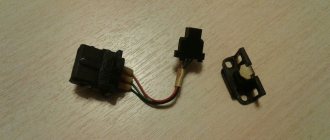
posistor
A posistor (RTS thermistor) is an electronic component that has a positive coefficient of resistance and performs dual functions: a heater and a temperature sensor. When high voltage or current is applied, the electronic component becomes hot. The higher the temperature becomes, the more its internal resistance increases, which means less current will flow through the element. Heating of the RTS component can occur under the influence of the external environment. In this case, it works as a temperature sensor. PTC resistors have a housing design in the form of round washers filled with enamel, or in the form of ceramic elements sequentially installed in a single housing.
posistor symbol used in circuits. In the diagram, a posistor has the following designation:
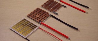
There are posistors with a relatively low TCR from 0.5% to 0.7% per 1 K, made on the basis of silicon. Their resistance changes almost linearly. Such posistors are widely used in temperature stabilization systems and in active cooling systems for power semiconductor switches in a variety of modern electronic devices, especially powerful ones. These components fit easily into circuit diagrams and do not take up much space on boards.
A typical posistor has the shape of a ceramic disk; sometimes several elements are installed in series in one housing, but more often - in a single design with a protective enamel coating. PTC resistors are often used as fuses to protect electrical circuits from voltage and current overloads, as well as temperature sensors and auto-stabilizing elements, due to their unpretentiousness and physical stability.
Example of a posistor
Application of a posistor
Thermistors are widely used in numerous fields of electronics, especially where precise temperature control is important. This is relevant for data transmission equipment, computer equipment, high-performance CPUs and high-precision industrial equipment.
One of the simplest and most popular uses of a thermistor is to effectively limit inrush current. When voltage is applied to the power supply from the network, an extremely sharp charge of a capacitor of significant capacity occurs, and a large charging current flows in the primary circuit, which can burn the diode bridge.
This current is limited here by the thermistor, that is, this component of the circuit changes its resistance depending on the current passing through it, since in accordance with Ohm's law it heats up. The thermistor then restores its original resistance after a few minutes, as soon as it cools down to room temperature.
Since the posistor is a fairly accurate component, its scope of application in radio electronics is as follows:
- protection of primary circuits of transformer windings;
- efficient current starter for electric motors;
- current limiter in heating devices (soldering irons, glue guns, heating radiators);
- demagnetization of old CRT TVs.
Scope of application of NTC thermistors:
- measuring the temperature of radio components of computers and mobile equipment (processors and memory chips, hard drives, video cards, etc.);
- in power supplies and lithium-ion (Li-ion) batteries as protection against overheating;
- in office equipment (laser printers and faxes);
- in 3D printers (for extruders and heated stages).
Thus, both components can control the temperature, but the resistance of the PTC thermistor tends to infinity as it heats up, while the resistance of the NTC thermistor tends to zero under the same conditions. To measure temperature, you need a controller that will calculate the resistance data of the components.
The main disadvantage of the thermistor is the discrepancy between the characteristics when manufactured using the same technical process. Components under the same conditions may produce different data, so when replacing one component with a similar one, recalibration is required. When used for a long time at elevated temperatures, NTC thermistors begin to degrade over time and need to be replaced. The maximum operating temperature of the sensors is 300 degrees Celsius.
We determine characteristics by marking
The wide range of applications of PTC thermistors implies their wide range, since the characteristics of these devices must correspond to various operating conditions. In this regard, for testing it is very important to determine the series of the element; marking will help us with this.
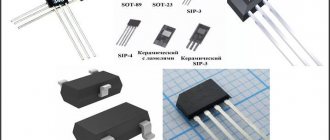
For example, let's take the radio component C831, its photograph is shown below. Let's see what can be determined from the inscriptions on the body of the part.
PTC posistor C831
Considering the inscription “RTS”, we can state that this element is a posistor “C831”. Having generated a request in a search engine (for example, “RTS C831 datasheet”), we find the specification (datasheet). From it we learn the name (B59831-C135-A70) and series (B598*1) of the part, as well as the main parameters (see Fig. 3) and purpose. The latter indicates that the element can play the role of a self-restoring fuse, protecting the circuit from short-circuit protection and overcurrent.
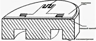
Bolometer device
The principle of operation of a bolometer is based on a change in the electrical resistance of a thermosensitive element due to heating under the influence of an absorbed flow of electromagnetic energy.
A spider web bolometer for measuring the cosmic microwave background radiation. Image courtesy of NASA/JPL-Caltech.
The main component of a bolometer is a very thin plate (for example, platinum or other conductive material) blackened to better absorb radiation. Due to its small thickness, the plate quickly heats up under the influence of radiation and its resistance increases. To measure small deviations in the resistance of the plate, it is included in a bridge circuit, which is balanced in the absence of illumination. Metal bolometers are often connected via a transformer input because they have very low self-resistance.
Conceptual diagram of a bolometer . Power, P, from the incident signal is absorbed and heats the thermal mass with heat capacity, C, and temperature, T. The thermal mass is connected to a reservoir of constant temperature through a connection to thermal conductivity, G. The temperature rise Δ T = P / C, and is measured using a resistive thermometer, which allows you to determine P. Internal thermal time constant τ = C/G
The first semiconductor bolometer was created by Bell during World War II. It was distinguished by its simplicity, reliability and high sensitivity. It was used in IR spectroscopy and thermal direction finding.
The first thermoresistive bolometers operated successfully on artificial Earth satellites, but were later supplanted by pyroelectric receivers.
The materials used for metal bolometers are platinum, nickel, and gold; for semiconductor bolometers, alloys of oxides of nickel, cobalt, and manganese are used.
A semiconductor bolometer consists of two film (up to 10 μm thick) thermistors. One of the thermistors directly exposed to irradiation is active. The second is compensatory. It is shielded from external radiation and is designed to compensate for changes in ambient temperature. Both thermistors are placed in a common sealed housing.
The sensitivity of a bolometer improves as the temperature of the sensing element decreases. Astronomy typically uses bolometers cooled to the temperature of liquid helium.
Main parameters of bolometers:
- resistance of the active thermistor at nominal temperature;
- operating voltage;
- sensitivity at a certain modulation frequency of the light flux;
- sensitivity threshold;
- time constant;
- the level of intrinsic noise - for metal ones, thermal noise predominates, for semiconductor ones - current noise.
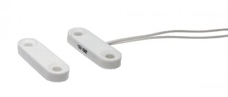
Why do we need a picture tube system?
On TV screens without a demagnetization system, the image would be distorted with a slight influence of the electromagnetic field. It is emitted by all household appliances, the surface of the Earth is penetrated by invisible waves.
Thus, amplifiers, large speakers, and heating elements are often located next to televisions. Without a screen mask, the image would be constantly distorted. During initial operation, a small current flows through the posistor, which does not cause it to heat up. In this case, the mask physically experiences tension from the emerging field.
This applied magnetic field demagnetizes the mask when the TV is turned on. Often this process is accompanied by a sound comparable to hitting a gong. The larger the screen diagonal, the higher the sound pitch. The posistor at this moment passes a high amplitude current through itself, which leads to its heating. The resistance increases and the element closes the circuit.
Hot electron bolometer
The hot electron bolometer (HEB) operates at cryogenic temperatures, typically within a few degrees of absolute zero. At these very low temperatures, the electron system in the metal is weakly coupled to the phonon system. The energy associated with an electron system pushes it out of thermal equilibrium with the phonon system, creating hot electrons. Phonons in the metal are usually well coupled to those in the substrate and act as a thermal reservoir. When describing the characteristics of HEB, the corresponding heat capacity is the electron heat capacity and the corresponding thermal conductivity is the electron-phonon thermal conductivity.
If the resistance of the absorbing element depends on the temperature of the electrons, then the resistance can be used as a thermometer of the electronic system. This is true for both semiconducting and superconducting materials at low temperatures. If the absorber element does not have temperature dependent resistance, as is typical for ordinary (non-superconducting) metals at very low temperatures, then the supplied resistance thermometer can be used to measure the electron temperature. [2
Step-by-step instructions for checking a posistor with a multimeter
For the testing process, in addition to the measuring device, you will need a soldering iron. Having prepared everything you need, we begin to act in the following order:
- We connect the part under test to the multimeter. It is advisable that the device be equipped with “crocodiles”; otherwise, we solder a wire to the terminals of the element and wind it onto different probe needles.
- We turn on the measurement mode of the least resistance (200 Ohms). The device will show the nominal value of R, characteristic of the model being tested (usually less than one to two tens of ohms). If the reading differs from the specification (taking into account the error), it can be stated that the radio component is faulty.
- We carefully heat the body of the tested part using a soldering iron, the R value will begin to increase sharply. If it remains unchanged, the element must be changed.
- We disconnect the multimeter from the part being tested, let it cool, and then repeat the steps described in steps 1 and 2. If the resistance has returned to the nominal value, then the radio component can most likely be considered serviceable.
Bolometric matrices and microbolometers
In the nineties of the 20th century, a real technological breakthrough occurred, dividing thermal imagers into two large groups - cooled and uncooled. This was due to the creation of modern bolometric matrices based on vanadium oxide and amorphous silicon. The resolution has increased over time from 16 x 16 to 640 x 480 elements. Sensitivity reached 0.1 degrees Celsius. Most devices based on bolometric matrices have become wearable by reducing their weight to hundreds of grams.
This was achieved by bolometric matrices, which made it possible to abandon expensive cooling systems that are still used to this day in modern photonic thermal imagers based on indium antimonide.
A microbolometer is a specific uncooled type of bolometer used as a detector in a thermal chamber. This is a thermal sensor grid of vanadium oxide or amorphous silicon on top of a corresponding silicon grid. Infrared radiation of a certain range of wavelengths strikes vanadium oxide or amorphous silicon and changes its electrical resistance. This change in resistance is measured and converted into temperatures, which can be represented graphically. A microbolometer grid typically comes in three sizes: a 640×480 array, a 320×240 array (384×288 amorphous silicon), or the less expensive 160×120 array. The different arrays provide the same resolution, with a larger array providing a wider field of view.
A microbolometer consists of an array of pixels, each of which consists of several layers. The cross-sectional diagram shown in Figure 1 is a generalized view of a pixel. Each company that makes microbolometers has their own unique procedure for making them, and they even use many different absorbent materials. In this example, the bottom layer consists of a silicon substrate and a readout integrated circuit (ROIC). Electrical contacts are deposited and then selectively etched. A reflector, such as a titanium mirror, is created under an IR-absorbing material. Since some of the light may pass through the absorption layer, the reflector redirects this light back to ensure maximum absorption possible, allowing a stronger signal to be generated. A temporary layer is then applied so that a gap can be created later in the process to thermally isolate the IR absorbing material from the ROIC. A layer of absorbent material is then applied and selectively etched to allow the final contacts to be made. To create the final bridge-like structure shown in Figure 1, the removal layer is removed so that the absorbent material is approximately 2 μm above the readout circuit. Because microbolometers are not cooled, the absorbent material must be thermally isolated from the bottom of the ROIC, and a bridge-type design allows this to happen. Once the pixel array is created, the microbolometer is sealed to increase the life of the device. In some cases, the entire manufacturing process is completed without breaking the vacuum.
In 2008, larger 1024×768 arrays were announced.
Rice. 1. Cross-sectional view of a microbolometer.
A microbolometer is a miniature bolometer, a set of sensors compressed to the smallest possible size. Microbolometers are not as “powerful” as photon receivers and do not have the greatest detection distance of cooled thermal imagers, but this disadvantage is more than compensated for by their low weight and convenience. Microbolometers have confidently occupied the niche of short-range observation and automatic control devices, where small dimensions and low power consumption are important.
Today, the size of such a sensor can be up to 11 micrometers. What is especially fascinating is that this microscopic detail also has even smaller elements. The microbolometer elements are suspended at a height of 2.5 µm. The width of the element legs is only 1.5-1.8 microns.
The smaller the structural elements of the matrix, the clearer the image your thermal imager can produce. Therefore, in the future, the main technological race in the field of thermal imaging will move from the macroworld to the microworld.
Most microbolometers contain a temperature-sensitive resistor, making them a passive electronic device. In 1994, one company, Electro-Optic Sensor Design (EOSD), began producing microbolometers that used a thin film transistor (TFT), which is a special type of field-effect transistor, an active microbolometer. The main change in these devices will be the addition of a gate electrode. Although the basic concepts of the devices are similar, using this design allows the advantages of TFT to be taken advantage of. Some benefits include adjusting the resistance and activation energy, and reducing periodic noise. As of 2004, this device was still undergoing testing and had not been used in commercial infrared imaging.
Element in the cooler circuit
If the back of the refrigerator - the radiator - does not heat up, then for self-repair you need to familiarize yourself with how to check the posistor. Two types of starters can be used in the refrigerator: with posistors and with electromagnetic relays. The former spend part of the energy on heat loss in the resistance of the element, the latter are less reliable, but do not heat up.
Most posistors in refrigerators should have a resistance of about 20–30 ohms. When heated, there may be several kiloohms. If the values significantly exceed those given, the element must be replaced. It is important to let the posistor cool to room temperature before taking measurements.
Advantages of microbolometers
- They are small and light. For applications requiring relatively short distances, the physical dimensions of the camera are even smaller. This property allows, for example, the installation of uncooled microbolometer thermal imagers on helmets.
- Provide real video output immediately after switching on.
- Low power consumption compared to thermal imagers with cooled detectors.
- Very high mean time between failures.
- Cheaper compared to cameras with cooled detectors.
Functional check
When devices malfunction, the state of the power circuits is first determined, and the task arises of how to check the varistor. First, an external examination is done.
Check for carbon deposits, blackening or mechanical damage. If any of this is present, the varistor needs to be replaced. Otherwise, unsolder at least one pin.
Without soldering the contacts, it will not be possible to measure the resistance of the varistor, since it is connected in parallel to the entire circuit of the device or some of its modules. Therefore, instead of determining the resistance of the varistor, at best, the total resistance of the entire device will be measured.
To desolder the lead, you need a soldering iron, desoldering pump, and pliers. The area around the terminal is heated with a soldering iron. The molten solder is pumped out using a desoldering pump. Use pliers to remove the varistor lead from the board.
Then a direct test of the varistor begins with a multimeter or ohmmeter. The operating mode switch is set to the “resistance measurement” position. The largest measurement scale (200 MΩ) is selected.
The probes are connected to the varistor terminals. Resistance is measured. Then the probes are swapped and the second value of the measured resistance is recorded.
The multimeter should show values in the tens of megohms. If in at least one measurement the multimeter shows values other than MOhm, it means that the varistor is faulty and needs to be replaced.
Some devices have a fuse in series with the varistor. Then just take it out and we get a version with one free contact. There is no need to solder anything.
Next, you should use a multimeter, and how the varistor is checked and measurements are taken was described above.
Application of a bolometer
The bolometer is sensitive to the entire spectrum of radiation. But it is used mainly in astronomy to detect radiation with submillimeter wavelengths: for this range, the bolometer is the most sensitive sensor. The source of thermal radiation can be the light of stars or the Sun, passed through a spectrometer and decomposed into thousands of spectral lines, the energy in each of which is very small.
Semiconductor bolometers are used, for example, in attitude control systems, for remotely measuring the temperature of objects, in sensors for detecting irradiation of military vehicles (for example, laser beam homing heads) and for the manufacture of bolometer matrices used in thermal imagers.
Used in PONAB systems to determine the heating of car axle boxes.
To demonstrate some of the problems of determining temperature by radiation, a Leslie cube was invented, the sides of which are made of different materials. The images of the Leslie cube on the right show the difference in emissive and reflective properties of different faces of the cube at the same cube temperature.
Heated Leslie cube. It can be seen that the black and white faces of the cube have a high emissivity and the thermal imager shows that the faces are hot. And the polished and matte edges of the cube are made of a material with a low emissivity but a high reflectance, which is why they look cold in the thermal imager and the heat of the hand is reflected in them.
Although bolometers can be used to measure radiation of any frequency, for most wavelength ranges there are other detection methods that are more sensitive. For submillimeter wavelengths (from about 200 μm to 1 mm wavelength, also known as far-infrared or terahertz), bolometers are among the most sensitive detectors available and are therefore used in astronomy at these wavelengths. To achieve the best sensitivity, they must be cooled to a fraction of a degree above absolute zero (typically 50 mK to 300 mK). Notable examples of bolometers used in submillimeter astronomy include the Herschel Space Observatory, the James Clerk Maxwell Telescope, and the Stratospheric Observatory for Infrared Astronomy (SOFIA).
How to fix it yourself
Finding the device is not difficult; it is located behind the back cover, next to the plug, which includes a demagnetization loop.
If the reason is magnetization of the device, it must be demagnetized. To do this, the device is unsoldered from the TV and connected to a demagnetization system.
But in most cases, damage to the device requires its replacement. You need to unsolder the old one and solder in a new one with similar characteristics. If we select the wrong device, it will not work.
Subscribe to our Social networks
Applications in particle physics
The term bolometer is also used in particle physics to refer to an unconventional particle detector. They use the same principle as described above. Bolometers are sensitive not only to light, but also to all types of energy. The operating principle is similar to a calorimeter in thermodynamics. However, proximity, ultra-low temperature and different uses of the device make its operational use very different. In high energy physics jargon, these devices are not called "calorimeters", since that term is already used to refer to another type of detector (see Calorimeter). Their use as particle detectors has been proposed since the early 20th century, but the first regular, albeit innovative, use was only in the 1980s due to the difficulties associated with cooling and operating the system at cryogenic temperatures. They can still be considered under development.
Deciphering the specifications of a specific model
These were the main parameters of the series, now let’s look at the specification for C831 (see Fig. 5).
B598 Series Model Specification*1
Brief transcript:
- The current value for normal operation, for our part is almost half an ampere, namely 470 mA (0.47 A).
- This parameter indicates the current at which the resistance value begins to change significantly upward. That is, when a current of 970 mA flows through C831, the “protection” of the device is triggered. It should be noted that this parameter is associated with the temperature transition point, since the passing current leads to heating of the element.
- The maximum permissible current value for switching to the “protective” mode, for the C831 is 7 A. Please note that the maximum voltage is indicated in the column, therefore, you can calculate the permissible amount of power dissipation, exceeding which will most likely lead to the destruction of the part.
- The response time for the C831 at a voltage of 265 volts and a current of 7 amperes will be less than 8 seconds.
- The amount of residual current required to maintain the protective mode of the radio component in question is 0.02 A. It follows from this that a power of 5.3 W (Ir x Vmax) is required to maintain the triggered state.
- Device resistance at a temperature of 25°C (3.7 Ohms for our model). Note that by measuring this parameter with a multimeter, checking the posistor for serviceability begins.
- The minimum resistance value for the C831 model is 2.6 Ohms. To complete the picture, we will once again present a graph of the temperature dependence, where the nominal and minimum values of R will be marked (see Fig. 6).
Figure 6. Temperature correlation graph for B59831, the values of RN and Rmin are marked in red.
Please note that at the initial stage of heating the radio component, its parameter R decreases slightly, that is, in a certain temperature range our model begins to exhibit NTS properties. This feature, to one degree or another, is characteristic of all posistors.
- Full model name (we have B59831-C135-A70), this information may be useful for searching for analogues.
Now, knowing the specification, you can move on to testing for functionality.
see also
- Thermocouple
- Scintillating bolometer
- Pyrometer
- Radiometer
- Tasimeter
- Thermistor
- Pyrheliometer
- Thermistor
- Microwave
I wrote an article about the thermistor especially for you. If you would like to contribute to the development of theory and practice, you can write a comment or send an article to my email in the contacts section. By doing this you will help other readers, because this is what you want to do? I hope that now you understand what a thermistor, posistor, bolometer, microbolometer is and what all this is needed for, and if you don’t understand, or have any comments, then don’t hesitate to write or ask in the comments, I will be happy to answer. In order to gain a deeper understanding, I strongly recommend that you study all the information from the category Electronics, Microelectronics, Component Base
Options for faults in picture tubes
If, when you first turn it on, the image is distorted or ripples and stripes are observed, then the posistor is most likely to blame. How to check an element in a circuit with a multimeter? It is easier to do this on a cold circuit, because the resistance of the posistor is minimal.
Often the soldered contacts simply fall off due to prolonged use. A posistor refers to circuit elements that constantly operate in a heated state. Using an ohmmeter, check the connection of the screen mask with the output of the second leg of the posistor. If it is minimal, this indicates a reliable connection. Perhaps the element does not trigger the cutoff.
If the posistor is faulty and short-circuited, then the power supply fuse blows when turned on for the first time. Provided that this occurs without a visible short circuit in the circuit, you can check the malfunction by completely disconnecting the screen mask and the posistor.
What is clearance and how important is it?
This value shows the possible deviation of a given series from the specified nominal value. A correctly calculated circuit must take this indicator into account, or appropriate adjustments are made after assembly. As you understand, our friends from the Celestial Empire do not bother themselves with this, which has a positive effect on the cost of their goods.
The result of such a policy was shown in Figure 4; the part works for some time until the limit of its safety margin is reached.
- We make a decision by comparing the readings of the multimeter with the nominal value; if the discrepancy goes beyond the error limits, the part definitely needs to be replaced.
Validation check
If the part is soldered, then this stage will guarantee its functionality. For testing we need to know the denomination. How to identify it by markings was written above.
The algorithm of our actions is as follows:
- We connect the probes as in the previous testing.
- We turn on the resistance measurement (the range is shown in Figure 6) in a mode greater than the nominal value, but as close as possible to it. For example, we need to test a 47 kOhm resistor, therefore, we need to select the “200K” range.
Figure 6. Resistance measurement ranges (marked in red) - We touch the terminals with the probes, take readings and compare them with the nominal value. If they do not match, and this can be guaranteed with a probability close to 100%, do not despair. Both the error of the device and the tolerance of the element itself should be taken into account. A little clarification is necessary here.
Color designation
Now color marking has been adopted, representing from three to six rings of different colors (see Fig. 2). There is no need to see this as the machinations of enemies, since this method allows you to set the denomination even on a heavily damaged part. And this is a significant factor, given that modern household electrical appliances are not equipped with circuit diagrams.
Rice.
2. Example of color marking Information on decoding this designation on components is easy to find on the Internet, so it makes no sense to present it within the framework of this article. There are also many calculator programs (including online) that allow you to obtain the necessary information.