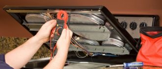
Rewinding an electric motor armature is one of the types of repair of commutator industrial and household DC and AC motors carried out by our company. The need to repair an electric power unit of this type arises during its long-term operation. Unlike asynchronous motors, commutator motors contain rubbing parts - current-carrying brushes and a commutator. This design feature determines the frequency of routine and major engine repairs in accordance with the maintenance plan.
In some cases, before repairing an electric motor armature, it is necessary to identify the causes of the failure using instrumental methods. This could be an interturn short circuit or a break in the lower layers of the armature winding. By checking the resistance, it is possible to determine this reason. The only way to restore functionality in this case is to rewind the armature of the electric motor.
How to determine if an angle grinder's armature is faulty
Signs of a broken armature angle grinder are: increased sparking of the brushes on the motor commutator, vibration of the motor at low speeds, rotation of the working shaft in different directions. If such symptoms are present, you should stop using the tool - this is dangerous. Suspicions can be easily verified using simple tests.
Visual inspection from outside
Troubleshooting should begin with a visual inspection of the angle grinder:
Carry out a general inspection of the instrument. Pay attention to the integrity of the power cord and the presence of voltage in the outlet. Using a voltage indicator, make sure that current is flowing to the motor commutator and the start button.
The indicator checks the integrity of the electrical circuit
Inspection of the device from the inside
If everything is in order with the power supply, but the angle grinder does not work, you will have to open the case to gain access to the motor. As a rule, disassembly is not difficult. But you need to follow simple rules that will help you avoid troubles during reassembly:
- Be sure to disconnect the device from the mains before disassembling.
- Remove the working disk and protective cover from the spindle.
- Open the case in a well-lit place, on a clean table surface.
- Remember the location of all parts and assemblies before disassembling. It is recommended to sketch or photograph the internal structure of the device.
- Place screws and fastening screws in a separate place so that they do not get lost.
It is best to inspect the engine under bright lighting so that all small parts are clearly visible. The armature should rotate freely around its axis; properly functioning bearings should not make any sound during operation. There should be no traces of melted wiring on the armature, the circuit windings should be intact, without breaks. You can smell the rotor. When there is an interturn short circuit, the insulating varnish burns and emits a persistent specific odor. But such a diagnosis requires some experience.
Continuity testing of circuits with a tester
If a visual inspection does not give clear results, it is recommended to continue the examination using a multimeter. Having set the mode switch to the ohmmeter position (200 Ohm range), you need to “ring” two adjacent armature lamellas with two probes. If the resistance on all turns is the same, this means that the windings are working properly. If on some pairs the tester shows a different resistance or an open circuit, there is a malfunction in this coil.
Using a multimeter in resistance measurement mode, check the integrity of the coils
A wire break can occur between the winding and the core. You should carefully examine the junction of the coils with the collector lamellas in the lower part of the armature, and visually check the soldering of the contacts.
Checking contacts with a light bulb
If you don’t have a tester, you can get out of the situation using a simple 12-volt light bulb. The power can be any, optimally 30–40 W. The voltage from the 12 volt battery must be applied to the plug of the angle grinder by inserting a light bulb into the gap in one wire. If the armature is working properly, if you rotate the spindle by hand, the light should light without changing brightness. If the heat changes, this is a sure sign of an interturn short circuit.
If the light does not light, this may indicate the following:
- The brushes may become stuck in the non-working position. The retaining spring has worked.
- There has been a break in the supply circuit.
- There is a short circuit or break in the stator winding.
There are other diagnostic methods, but they require more sophisticated equipment, which is not usually used at home. An experienced technician will determine the breakdown with a high degree of accuracy using a “punch” or a simple transformer with a cut toroidal core and one primary winding.
Working with an ohmmeter
Types of electric motors and their connection diagrams for 220 and 380 V
Sincere could occur due to the loss of electrical contact in one of the lamellas. To measure resistance, it is recommended to place probes on the side of the current collectors. While rotating the motor shaft, observe the dial readings. The screen should show zero values. If the numbers slip by even a few ohms, then this indicates carbon deposits. When an infinite value appears, an open circuit is judged.
Regardless of the results, you should next check the resistance between each adjacent lamellas. It should be the same for each measurement. In case of deviations, you need to inspect all the connections of the coils and the contact surface of the brushes. The brushes themselves should wear evenly. If chipped or cracked, they must be replaced.
The coils are connected to the core by wiring that may have come loose. Solder often does not withstand shock from drops. In a starter, the current through the contacts can reach 50A, which leads to burnout of poor-quality connections. External inspection determines the location of damage. If no malfunction is found, then measure the resistance between the lamella and the coil itself.
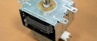
Stator in different types of electric motors
The stator is an integral component of an electric machine that remains stationary while the engine is running. The rotor is the rotating part of an electric motor that transmits mechanical energy to the output shaft. Another name for a rotor is an armature.
Synchronous or commutator motor
Electric current is transmitted to the commutator lamellas by graphite brushes. Such an electric motor will operate in both direct and alternating current networks. The pulsating magnetic field generated by the stator windings will interact with the pulsating magnetic field generated by the armature windings. The rotor will begin to rotate. Such electric motors are widely used in various household and industrial appliances: electric drills, vacuum cleaners, power drives of machine tools, and electric vehicles.
Interesting. Motors of this type have another name - synchronous. This means that the rotation speed of the rotor is equal to the rotation speed of the electromagnetic field arising in the motor.
Asynchronous motors
The overwhelming majority of electric motors used both in industry and in everyday life are asynchronous electric motors with squirrel-cage rotors. Such motors are used in three-phase and single-phase AC networks.
Asynchronous motor
The stator structure is assembled from a large number of steel plates and is located in a base housing cast from non-magnetic metals: cast iron or aluminum.
Stacked motor stator
Plate material – electrical steel. The plates are insulated from each other with a special dielectric varnish. The stator has longitudinal grooves where three windings are placed, shifted relative to the axis of rotation of the electric motor by 120 degrees from each other. The rotor is also made of insulated electrical steel plates. Rods made of aluminum, less often copper, are placed in the grooves of the rotor, connected at the ends by slip rings. Hence the name - squirrel-cage rotor. This design, called a “squirrel wheel,” plays the role of a rotor winding.
Below is a cross-sectional view of an asynchronous electric motor. You can clearly see what a stacked stator is.
Sectional view of an asynchronous motor
The motor windings can be connected to a three-phase electrical network in a delta or star configuration.
Three-phase motor connection options
The circuit is switched in the motor terminal box, called born or brno.
When three-phase voltage is applied, pulsating currents arise in the stator windings, which cause the appearance of a rotating magnetic field in the stator. This field crosses the conductive rods of the rotor, in which secondary pulsating currents are induced. The result is the appearance of a magnetic field in the rotor. The magnetic fields of the stator and rotor interact and cause the rods of the “squirrel wheel” to rotate, along with the rotor itself. The armature rotates at a speed slightly lower than the magnetic field of the stator.
The magnitude of this difference is called slip and can range from 2 to 8%. Due to the presence of slip, motors of this design are called asynchronous. The sliding effect is physically necessary for the operation of an asynchronous motor - there will be no lag in the rotation of the rotor from the magnetic field of the stator, no current will be induced in the rotor rods, and the magnetic field in the armature causing the rotor to rotate will disappear.
Features of direct connection to the power supply
When magnetic starters are used, this will make it possible to control asynchronous electric motors by directly connecting the motor to alternating current networks.
Using magnetic starters, the following circuits are implemented:
- reverse start;
- irreversible start.
When using thermal relays, it will be possible to protect the electric motor from a current that far exceeds the rated value. The disadvantages of direct commutation of the windings of asynchronous motors with the network include large starting currents during the start of the electric motor.
Stator protection with thermal relay
During operation, the electric motor may consume increased current from the network and experience strong heating. The reasons may be different, for example, too much load on the shaft, frequent turning on and off of the motor, increased ambient temperature. Such abnormal operating conditions can lead to overheating of the stator windings and their failure. To prevent damage to the electric motor, one or two bimetallic thermal relays are installed in the stator system - these are thermal switches called klixons.
Klixon thermal switch
When the stator temperature rises above the set value, the bimetallic klixon contact opens. The thermal switch opens the power supply circuit to the control coil of the power contactor, which supplies voltage to the electric motor. The contactor disconnects the electric motor from the power supply. Further switching on of the contactor and, therefore, the electric motor is possible only after cooling the stator windings and closing the bimetallic pair of the thermal switch.
Motor protection options
There are various devices that provide additional protection for the engine and minimize damage.
- Thermal relays and automatic motors. They reliably protect the electric motor from damage due to excess current.
- Electronic relays. It is a microprocessor that analyzes the voltage value.
- Thermal relays and thermistors. They help avoid breakdowns when the thermal protection does not work due to overheating.
- Frequency converter. It carries several functions related to overload protection.
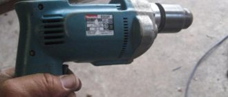
How to determine the integrity of the stator without disassembling the hammer drill
To determine the integrity of the stator, you need to ring its windings, measure the winding resistance and insulation resistance.
Stator and rotor continuity diagram
To measure the winding resistance of a Makita hammer drill, you need to connect one end of the tester to the freed brush holder, and the other to one of the ends of the electric plug. If the device does not show anything, change the other end of the plug. If the resistance is infinity, there is a break in the stator and it requires replacement or repair. Don’t forget, you can’t do without a circuit diagram of a Makita 2450,2470 rotary hammer.
Simple connection diagram for a commutator motor
If some kind of resistance is shown, it is important to measure its exact value. As a rule, the resistance of the stator winding of the Makita-2450 hammer drill at a temperature of +20ºС lies within 25 Ohms
To understand in more detail why the armature commutator sparks and which brushes are better? The video will help you figure it out; at the end of the video review there are important tips on choosing brushes
Video:
How to remove the stator of a Makita 2450 and 2470 rotary hammer for accurate diagnosis and repair
To remove the stator pos. 59, you need to remove the brushes and unscrew the four screws securing the cover of the mechanical unit. They screw into the end of the lid. By pulling the black housing and the green one in different directions, you will release the housing with the stator. The stator is mounted in a green housing.
To remove it, you need to remove the plastic gasket pos. 58 and tap on the end of the body with a wooden mallet or block. The stator will stick out on its own, all that remains is to pull it out, blow it off and check it completely.
And here is the stator
If you have a short circuit tester, you can immediately check the stator for a short circuit. The device is called IK-32. Procedure for checking stator windings For an accurate check, disconnect the two stator windings from each other via an electrical circuit. Check the resistance of each winding, they should be exactly the same. If there is a difference in resistance, the winding with lower resistance most likely has an interturn short circuit.
Checking the stator of the Makita 2470 and 2450 rotary hammer with your own hands. Diagnostics of the armature and stator using a short-circuit device and homemade equipment.
Video:
How to check the suitability of a Makita hammer drill rotor
Checking the suitability of the rotor in a Makita hammer drill begins by removing it from the housing. But first we need to conduct external research. If in the rotor a spark from the brushes on the commutator covers the weight of the commutator, if during operation the hammer drill does not develop speed and its power has dropped, this is the first sign of a rotor malfunction.
How to remove the rotor from the housing To remove the rotor from the housing, you need to separate the black and green housings, as in the case of removing the stator.
We take out the rotor
Having disconnected the stator housing, take the gearbox housing (black) in your right hand, and the rotor in your left hand and pull in different directions until they are completely separated. The rotor is held in the gearbox by friction of helical gears.
And this is the rotor
Carefully inspect the rotor manifold. There should be no traces of scratches from brushes. The collector lamellas must be clean.
Clean collector
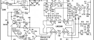
To check the integrity of the collector, you must use a short circuit detection device. It is easiest to test the circuits according to the circuit diagram of the Makita 2470.2450 rotary hammer. By the way, you can make such a device yourself if you know how to use a soldering iron.
Circuit of short-circuit turns probe
If you are convinced that the rotor is faulty, you can install a new one, or you can try to restore the failed one.
Possible malfunctions of the commutator motor
Sometimes even people familiar with the structure of the mechanism have little idea how to check a commutator motor. Below we will talk about all possible malfunctions and ways to identify and eliminate them.
Broken contacts. This is indicated by active sparking. Interturn short circuit (short circuit of windings in the collector). It also causes sparking. Wear of the brush-collector unit. At the same time, it turns black and sparking appears. Usually the problem is solved by replacing old elements with new ones. To remove the assembly, move the lock and unscrew the mounting bolt (depending on the engine model). Darkening of the contact part of the collector. Often it is enough to clean it with fine sandpaper. Formation of a groove at the point of contact of the brushes with the commutator. It is necessary to perform the grooving of the unit on the machine. Bearing wear. This malfunction can be determined by increased vibration of the housing during engine operation and beating of the cartridge. In this case, bearing replacement is required. The armature touches the stator. Sometimes replacing the armature is enough, but in some cases you will have to replace both the armature and the stator. Control failure on the microcontroller. Installing a new microcontroller is the optimal solution to the problem. Burnout or breakage of windings
Pay attention to their color and integrity. Blackening of the entire winding body or part thereof indicates burnout; a break is easily determined by visual inspection
In this case, they need to be replaced or rewinded. Graphite dust in the space between the lamellas. Your appliance just needs cleaning. Burnout of wire insulation. A characteristic odor will indicate this problem.
In all of the above cases, restoring the electric motor manifold with your own hands is quite possible if you have the necessary spare parts and tools. Only if you do not have experience in rewinding windings, it is better to contact the appropriate service. After troubleshooting, reconnect all parts in reverse order.
Rewinding motors of drills and grinders
To begin with, the device should be disassembled and the engine inspected. The winding should not be removed immediately: first of all, you need to find out the number of its turns. This is not difficult to do: just separate the top of the coils and cut it off. After this, you need to burn it with a burner. Now you can count the number of its turns.
If you decide to rewind the rotor yourself, then you do not need to remove the collector. It is worth examining it and measuring the value of its resistance in relation to the body (this value should not be less than 0.2 Mohm). The collector should be cleaned of what remains of the previous winding and grooves should be cut in its contact part. This is necessary in order to then insert the ends of the coils into these places and seal them.
After cleaning, the anchor must be sleeved. The sleeves are made of electrical type cardboard, 0.2 millimeters thick, after which they are inserted into the anchor grooves. Only after completing these procedures can you begin to rewind the motor coils.
If it is decided to use circular winding, then the coil should be laid in a sequential manner until all the slots are filled. The laying direction should be chosen in the direction opposite to the clock hand (if the anchor lies with the shaft towards the winder). This type of installation is called “right-hand installation”.
In the collector area, the winding is fastened with a bandage. This should be done using a thick thread of cotton fabric, laid in several tight turns and tied tightly. There is no need to use nylon threads, since nylon can easily melt during operation of the device.
After this, you need to check the product for the absence of interturn short circuits and breaks in the winding. This is best done before the product goes into impregnation, because before impregnation it is much easier to change the winding on the armature.
To secure the resulting winding, you need to impregnate it. This can be done using regular epoxy, designed to be hot cured with the addition of a plasticizer. If this procedure is performed at home, then any varnish can be used. When the impregnation is completed and dried, it is necessary to perform a grooving. How you do this will determine how much the armature will spark. The amount of beating should not be more than 5 hundredths of a millimeter, and the cutter must be properly sharpened to work with copper. After completing all these procedures, you need to re-check the product for short circuits.
Rules for repairing a rotor with a short-circuited winding
In these parts, the squirrel cage is most often damaged, as a result the rods weaken in the grooves and the contact is broken in the place where the rods are soldered to the short-circuited ring. As a result, a crack forms and the rod breaks. Due to the weakening of the fastenings of the rods in the grooves, its vibration increases. The result will be deformation, and at the end there will be a crack (just in those places where the rod comes out of the grooves and the short-circuited rings are connected). It is they that lead to breaks in the rods, and those ends that break damage the frontal part and its insulation. All this is typical for electric motors that have large starts.
If you identify defects in time, you can save the engine. But for this it will have to be disassembled. If the motor is working, then some signs may indicate the presence of broken rods. For example, vibration increases because the fastenings become loose or the spacer wedges in the winding rods break.
What to do if the startup time has increased
There are units that have difficulty starting the motor and do not develop the rated frequency. If several rods break, it will not even move. The asymmetry of magnetic fluxes causes strong vibration and additional forces appear for the electric motor to work normally.
When a pair of rods break, all of the above signs do not appear so strongly and therefore it is very difficult to detect a possible defect that has arisen in the squirrel cage. You have to inspect the unit visually. And don’t forget about inspecting the short-circuited winding:
- what are the colors of the burns on the short-circuited rings in the places where they are connected to the rod;
- wavy bends of segments that may appear due to unevenly elongated rods;
- burnt bolts connecting some of the launch cage segments;
- in which direction the ends of the rod are bent in the direction of the rotating unit - they arise when twisted into rings.
Each of the above defects can appear in equipment that has high peripheral speeds and a massive short-circuit ring.
You can find deflections that protrude from the end of the active steel rod. These defects are present in many squirrel cell rods. It happens in both synchronous and asynchronous motors. Other faults include a moving squirrel cage along its axis.
If the short-circuited cage does not break during operation, then these damages will not manifest themselves in any way and can only be identified after a careful inspection of the short-circuited windings during preventive repairs. You should look very carefully for cracks at the end of the rod that protrudes. It is better to use a chemical, electromagnetic or optical method to help.
How to remove damaged rods from a groove
It all depends on the design of the rod. If we are talking about bottle profile rods, which sit tightly in the grooves due to the existing caulking along the entire length of the unit, then they need to be removed by drilling, using drills with extended shanks or by first cutting a longitudinal slot two to three millimeters wide in the rods. This operation is performed with vulcanite stones, which were originally designed to cut pipes.
The devices are installed on carriages moved along guides made from angles and attached with a bracket to the shaft cages. Because of this cut slot, the fastening of the rod in the grooves will loosen and it may come out by about 5-8 cm. You need to grab it with a clamp - it will help to completely remove the rod from its groove. The short-circuited winding can be partially repaired not only directly in the workshop itself, but also at the place where the electric motor will be installed. But only in the case where this does not require resorting to machining of rods and short-circuit rings.
How to solder copper rods
If cracks are found on those parts of the rod that protrude from the active parts of the steel, then measures will have to be taken to eliminate them. When the crack is shallow and no more than ¼ of the rod itself, then it can be welded, but before that, cut out a gap in the deepening area that is larger than the size of the crack.
When it comes to deep cracks, the rod is simply cut and the section that is soldered to the short-circuited ring is drilled out. Through the hole that formed in the ring, you need to drill another hole in the end with a diameter of no more than half the diameter of the rod itself. In this place you need to install and solder a copper insert. Before soldering, you need to degrease and etch the end rings. This can be done using a clean rag, previously soaked in washing liquid. Etch for half a minute with a solution of nitric acid at a temperature of twenty degrees. And the etched area should then be rinsed under hot water. Then wipe dry and dry.
Winding repair
Check and enable
Before starting the engine for the first time after repair, it must be thoroughly checked. To begin with, all inserted “coils” ring. This will help you find out if there is a break or poor contact. The resistance is measured between the “layings” so that a short circuit does not occur when turned on.
You should not immediately supply 220 V to the engine; it is better to supply a reduced voltage. Let the rotor spin slowly, the main thing here is to find out if the engine is overheating. If everything went well and no smoke appeared, then the engine repair was successful.
There are many photos on the Internet on rewinding motors. This will help beginners visually familiarize themselves with the process.
How to replace an old gearbox with a new one
Grinders differ in size, power, and manufacturers, but the principle of component layout is the same. The new motor armature for the angle grinder is selected strictly in accordance with the model of your tool.
- After unscrewing all the fastening bolts of the casing, housing and gearbox, remove the gearbox with the armature from the housing.
Usually the gearbox and the armature are rigidly attached to each other. To separate them, you need to disassemble the gearbox. Gearbox with anchor - Unscrew the mounting bolts.
- The rotor shaft is screwed to the gearbox housing with a nut. Unscrew it. Remove the gear.
- Next comes the bearing. To remove it, sometimes it is enough to knock on the gearbox housing with a wooden block. But more often than not, a stuck bearing cannot be removed without some tricks. Between the impeller and the bearing there is a plate, which is bolted to the gearbox with two bolts. To get to them, break off a piece of the plastic impeller or use a heated nail to burn two symmetrical holes. The second hole is necessary for balancing if you are not going to change the impeller.
- Unscrew both bolts, tap the gearbox housing with a wooden block, and the armature will detach from it. In this case, the bearing will remain on the shaft. Remove all bearings from the shaft using a puller.
Video: how to film and what difficulties may arise
Place the new bearing into the gear housing on the rotor side. Screw on the plate that caused the impeller to break. Insert the gear inside the housing and tighten the nut so that it fits into the grooves of the gear. Place the impeller on the new armature and insert the armature into the gearbox housing. Tighten the nut.
Replacing the anchor yourself at home
Practice shows that if you decide to replace the armature of an angle grinder, then it is best to change it together with the support bearings and the engine cooling impeller.
To replace you will need:
- New angle grinder anchor. Must match your model. Interchange with other models is not permitted.
- Screwdrivers, wrenches.
- A soft brush and cloth for wiping the mechanism.
How to remove an anchor
Replacing the anchor begins with disassembling the angle grinder. The following steps are performed:
- Use a screwdriver to unscrew the brush units on both sides. The brushes are removed.
Video: replacing bearings on an angle grinder
How to put an anchor in place
To install a new angle grinder anchor in place, you should take a new part, and then assemble the tool in the reverse order. The sequence of actions is as follows:
- A fixation disk is installed on the armature shaft.
- The bearing is installed using the pressing method.
- The small gear is fitted and secured with a retaining ring.
- The anchor is inserted into the gearbox housing, and the docking holes are aligned.
- The gearbox mounting bolts are tightened.
- The anchor with the gearbox is inserted into the body of the angle grinder and fixed.
- The brushes are deposited in their places and closed with lids.
After completing these steps, the grinder is ready for work. The anchor has been replaced.
Video: how to check an angle grinder
An ancient Sufi wisdom says: “A smart person is one who is able to come out of a difficult situation with dignity. But the one who does not find himself in such a situation is wise.” By following the rules for operating household appliances and preventing the motor from overheating, you can avoid breakdowns and troubles in the operation of the angle grinder. Keeping and storing the tool clean and dry will prevent its mechanisms from contamination and oxidation of current-carrying elements. Timely maintenance of the tool is guaranteed to eliminate unpleasant surprises during operation.
Most household devices (vacuum cleaners, washing machines, meat grinders, hair dryers, tools, etc.) use a commutator motor. Like any unit, it can fail. Repair of commutator electric motors can be carried out at home, without the help of specialists. To do this, it is enough to know what they are and have at least a minimum of experience.
Repair of pole coils
Pole coils are called excitation windings, which, according to their purpose, are divided into coils of the main and additional poles of DC machines. The main shunt coils consist of many turns of thin wire, and the series coils have a small number of turns of heavy gauge wire, wound from bare copper bars laid flat or on edge.
After identifying the faulty coil, it is replaced by assembling the coil at the poles. New pole coils are wound on special machines using frames or templates. Pole coils are made by winding insulated wire directly onto an insulated pole, previously cleaned and coated with glypthal varnish. Lacquered fabric is glued to the pole and wrapped in several layers of micafolium impregnated with asbestos varnish. After winding, each layer of micafolia is ironed with a hot iron and wiped with a clean cloth. A layer of varnished fabric is glued onto the last layer of micafolia. Having insulated the pole, put the lower insulating washer on it, wind the coil, put on the upper insulating washer and wedge the coil onto the pole with wooden wedges.
The coils of additional poles are repaired, restoring the insulation of the turns. The coil is cleaned of old insulation and placed on a special mandrel. The insulating material is asbestos paper 0.3 mm thick, cut into frames according to the size of the turns. The number of gaskets must be equal to the number of turns. On both sides they are coated with a thin layer of bakelite or glypthal varnish. The coil turns are spread apart on a mandrel and spacers are placed between them. Then they tighten the coil with cotton tape and press it. The coil is pressed on a metal mandrel, onto which an insulating washer is placed, then the coil is installed, covered with a second washer and the coil is compressed. By heating the welding transformer to 120 C, the coil is further compressed. Cool it in the pressed position to 25 - 30 °C. After removal from the mandrel, the coil is cooled, coated with air-drying varnish and kept at a temperature of 20 - 25 ° C for 10 - 12 hours.
Rice. 107. Options for insulating pole cores and pole coils:
1, 2, 4 — getinax; 3 — cotton tape; 5 — electric cardboard; 6 - textolite.
The outer surface of the coil is insulated (Fig. 107) alternately with asbestos and micanite tapes, secured with taffeta tape, which is then varnished. The coil is placed on an additional pole and wedged with wooden wedges.
Wire winding
There are several ways to rewind the stator of an asynchronous electric motor, but when choosing any of them, be sure to remember each step during disassembly. This will make the repair easier, and significantly. For winding, you will need a copper wire in varnish insulation; its cross-section should be the same as on the electric motor being repaired.
Make sure that there is no damage to the housing and magnetic circuit of the electric motor. After this, it is necessary to make sleeves and install them in the grooves on the stator. In order not to count the number of turns, or to determine the thickness, strength and heat resistance of materials for the manufacture of sleeves, you can use reference literature. To do this, you need to know the type and model of the asynchronous motor.
All work in specialized workshops is carried out on machines. The machine even calculates the number of turns. But how can you rewind an electric motor at home if there are no such conditions? You will have to calculate everything yourself, or take all the data from the service book for the electric motor.
In what cases can you save an anchor and restore it yourself?
If damage to the armature is determined with guaranteed accuracy, the part must be removed from the electric motor. Disassembling the motor must be done with special care, after removing the brushes and disconnecting the power terminals. The rotor is removed along with the support bearings and the motor cooling impeller; they form a single whole with it.
If most of the wiring in the armature is damaged and the balancing is disrupted as a result of overheating, it is better to replace it entirely. An imbalance is indicated by increased vibration and an uneven hum when the mechanism operates.
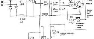
Read also: Welding inverter circuit with 8 23n50 transistors
How to rewind an anchor - step-by-step instructions
If the balancing of the armature is not disturbed, and the problem is only in damaged windings, then such an armature can be restored independently by rewinding the coils. Rewinding a rotor at home requires a lot of patience and accuracy.
The technician must have skills in working with a soldering iron and instruments for diagnosing electrical circuits. If you are unsure of your abilities, it is better to take the engine to a workshop for repairs or replace the entire armature yourself.
To rewind the anchor yourself you will need:
- wire for a new winding. A copper core with a diameter exactly matching the old conductor is used;
- dielectric paper for insulating the winding from the core;
- varnish for filling coils;
- soldering iron with tin-lead solder and rosin.
Before rewinding, it is important to count the number of turns of wire in the winding and wind the same amount of new conductor onto the coils.
The rewinding process consists of the following steps:
- Dismantling old windings. They must be carefully removed without damaging the metal body of the armature. If any burrs or damage are found on the body, they must be smoothed out with a file or sanded with emery. Sometimes, to completely clean the body of slag, craftsmen prefer to burn it with a torch.
- Preparing the collector for connecting a new wire. There is no need to remove the manifold. You should inspect the lamellas and measure the resistance of the contacts in relation to the housing with a megger or multimeter. It should be no more than 0.25 MOhm.
- Removing old wiring on the manifold. Carefully remove the remaining wires and cut grooves in the contacts. In the future, the ends of the coil wires will be inserted into the grooves.
- Installation of sleeves for anchors. The sleeves are made of dielectric material 0.3 mm thick, for example, electrical cardboard. Cut a certain number of sleeves and insert them into the grooves of the cleaned anchor.
- Rewinding reels. The end of the new conductor is soldered to the end of the lamella and wound in successive circular movements, counterclockwise. This laying is called “laying to the right.” Winding Repeat for all coils. Near the collector, tie the wires together with a thick thread of cotton fabric (it is prohibited to use nylon, as it melts when heated).
- Checking the winding quality. After laying all the windings, check with a multimeter for the absence of interturn short circuits and possible breaks.
- Finishing processing. Treat the finished coil with varnish or epoxy resin to secure the winding. In factory conditions, the impregnation is dried in special ovens. You can do this at home in the oven. As an option, use quick-drying varnishes for impregnation, applying the coating in several layers.
Slip of an asynchronous motor. Rotor speed
A distinctive feature of an asynchronous motor is that the rotor speed n2 is less than the synchronous speed of the stator magnetic field n1.
This is explained by the fact that the EMF in the rotor winding rods is induced only when the rotation speed n2 is unequal, where s is the slip of the asynchronous electric motor, n1 is the rotation frequency of the stator magnetic field, rpm, n2 is the rotor rotation speed, rpm,
Let us consider the case when the rotor rotation frequency coincides with the rotation frequency of the stator magnetic field. In this case, the relative magnetic field of the rotor will be constant, thus no EMF, and therefore no current, will be created in the rotor rods. This means that the force acting on the rotor will be zero. This will slow down the rotor. After which an alternating magnetic field will again act on the rotor rods, thus the induced current and force will increase. In reality, the rotor of an asynchronous electric motor will never reach the rotation speed of the stator magnetic field. The rotor will rotate at a certain speed which is slightly less than the synchronous speed.
The slip of an asynchronous motor can vary in the range from 0 to 1, i.e. 0-100%. If s~0, then this corresponds to the idle mode, when the engine rotor experiences practically no counteracting torque; if s=1 - short circuit mode, in which the motor rotor is stationary (n2 = 0). Slip depends on the mechanical load on the motor shaft and increases with its growth.
The slip corresponding to the rated load of the motor is called rated slip. For low and medium power asynchronous motors, the rated slip varies from 8% to 2%.
Energy conversion
An asynchronous motor converts electrical energy supplied to the stator windings into mechanical energy (rotation of the rotor shaft). But the input and output power are not equal to each other since energy losses occur during conversion: friction, heating, eddy currents and hysteresis losses. This energy is dissipated as heat. Therefore, an asynchronous electric motor has a fan for cooling.
Prices for repairing an electric motor armature
| Power, kWt) | Rotation speed, rpm | |||
| 3000 | 1500 | 1000 | 750 | |
| Up to 1.5 | 2740 | 2806 | 3417 | 4057 |
| 2.2 | 3090 | 3245 | 4154 | 4897 |
| 3 | 3642 | 3901 | 4973 | 5179 |
| 4 | 5012 | 4652 | 5413 | 6804 |
| 5.5 | 5296 | 5301 | 5978 | 7511 |
| 7.5 | 6630 | 6919 | 7312 | 11021 |
| 11 | 8139 | 8147 | 9937 | 13182 |
| 15 | 12088 | 12049 | 11737 | 14803 |
| 18,5 | 13001 | 13345 | 15217 | 24450 |
| 22 | 15057 | 15805 | 23408 | 25522 |
| 30 | 17648 | 18202 | 25857 | 29275 |
| 37 | 23803 | 25949 | 30677 | 40080 |
| 45 | 29055 | 28737 | 38389 | 48070 |
| 55 | 34546 | 32811 | 41481 | 60759 |
| 75 | 44670 | 48812 | 64472 | 82899 |
| 90 | 47893 | 51078 | 78166 | 99898 |
| 110 | 67202 | 73052 | 95759 | 122517 |
| 132 | 80848 | 87962 | 114110 | 147423 |
| 160 | 98012 | 106439 | 138740 | 179116 |
| 200 | 123101 | 132548 | 173924 | ———- |
| 250 | 154120 | 167435 | ———- | ——— |
| 320 | 237156 | ————— | ———- | ———— |
| kW | 3000 rpm | 1500 rpm | 1000 rpm | 750 rpm |
COEFFICIENTS USED IN THE CALCULATION:
- Single-phase - 1.5;
- Foreign production -1.5;
- Explosion-proof – 1.3;
- Urgent – 1.5;
- Two-speed – 1.5; Two-speed with independent windings – 2.
- Old model type AO, A, VAO -1.5
How to clean
The condition of the commutator significantly affects the service life of the brushes, will significantly reduce sparking, which will make the grinder work at parameters close to the nominal ones. Why is it necessary to clean it regularly?
One of the options for collector cleaning technology is shown in the following video. Available consumables and tools are:
- emery cloth with abrasive numbers 1000 and 2000;
- felt circle with a cylindrical shank;
- screwdriver or drill;
- paste GOI;
- needle;
- needle file;
- small brush.
The technology of operations is quite simple
Important: do not forget to chamfer the lamellas, which is why the needle file is needed here
How to check the condition of the brushes
When installing new carbon brushes, it is recommended to grind them in for a better fit to the commutator surface.
It is best to adjust carbon brushes using a homemade grinder. The lap is a shaft on which sandpaper is attached. The easiest way is to make the shaft from wood with a diameter equal to the diameter of the commutator, turning the workpiece on a lathe. A metal rod is inserted tightly along the axis inside the shaft. The device is attached to the chuck of an electric drill, the drill is turned on, and the brushes are brought to a rotating emery wheel.
The adjustment should be carried out carefully, periodically applying the brushes to the rotor commutator to check their clearance.
Having ground the brushes to the commutator, it is recommended to check the correct fastening of the brush holders before installation. When factory installed, the brush holders are set to neutral, which minimizes sparking on the commutator. If there are no factory marks, then the installation of the brush holders is adjusted by moving the brush holder in the direction opposite to the rotation of the rotor until a minimum spark is formed.
The brushes should not dangle in the brush holder, but should be pressed tightly against the commutator lamellas. The pressing force is regulated by springs in the brush holder.
Sparking faulty collector
An increase in sparking on the rotor commutator may appear due to a short circuit of the armature, a break in the armature coils, or a short circuit of the windings to the armature body. All these faults can be eliminated only with a major overhaul of the rotor.
The main malfunctions of an angle grinder and their causes
According to statistics, most cases of angle grinder failure are associated with the electrical part of the device. Some damage may be minor, which allows you to repair the angle grinder yourself. But, for example, if the motor windings burn out, only a specialist can repair an angle grinder.
Grinder won't turn on
The reasons that the angle grinder does not turn on may be the following:
- the electrical plug is faulty;
- the electrical cable is faulty;
- the start button is broken;
- the contact between the power cable and the button is broken;
- break in the contact wire of the electric brush;
- severe wear of electric brushes;
- failure of the rotor or stator windings.
The angle grinder does not develop speed
The reasons why the angle grinder does not gain momentum can be different.
- Damage to the speed control unit. To check this version, you need to connect the device’s motor directly, bypassing the regulator, and check the operation of the device.
- Failure of the electrical cable due to constant kinks or mechanical damage. Because of this, the damaged wire begins to heat up under load, and engine speed drops.
- Collector contamination with dust. Contaminants must be removed with alcohol.
- Problems with brushes. They may be worn out or have a short contact wire as shown in the following photo.
Although the brush is half worn out, it is still fully functional. In this case, a short contact wire prevents the spring from pressing the electrode to the collector. This situation may also be the reason why the angle grinder stopped working normally.
The electric motor is heating up
The reasons why the angle grinder is heating up may be the following.
- Incorrect operating mode of the device. As a result of overloads, the electric motor can become very hot, which often leads to burnout of the windings.
- Destruction of bearings located on the armature. As a result, the rotor clings to the stator, engine operation becomes difficult, and the windings overheat. The problem is solved by replacing the bearings.
- Clogged ventilation ducts through which air flows to cool the engine. The ventilation openings must be cleared of dust.
- Damage to the impeller used to cool the engine. It is installed on the rotor, on the side opposite to the collector. If the impeller is broken, it must be replaced with a new one.
- Interturn short circuits of stator and rotor windings. It will be necessary to rewind the reels or replace these parts with new ones.
Bulgarian sparkles
If you notice strong sparking when you turn on the angle grinder in the place where the collector is located, then the reasons for this trouble may be the following.
- Damage to the armature winding: break of one or more sections of the winding, interturn short circuit. With such breakdowns, increased noise appears, engine speed drops and brushes burn.
- The contact between the collector plates and the winding is broken.
- Weak brush pressure. During long-term operation of the angle grinder, the springs overheat and can “anneal”, thereby losing their elasticity.
- Engine rotor imbalance.
- Damage to the cylindrical surface of the collector. This sometimes happens after rewinding, if the armature is not turned on a lathe, but is immediately installed in the machine. In this case, you can also observe that the brushes spark excessively.
- The insulation between the collector lamellas is broken. There may also be clogging of the track grooves with graphite or a breakdown between the lamellas.
- Bearing wear, which causes the rotor to run out, also causes the brushes to spark heavily.
- Violation of the geometry of the armature shaft. This usually happens when the electric motor is disassembled carelessly and the shaft bends.
- Wrong brand of graphite brushes installed. Brushes are selected based on the expected speed and voltage.
- Raising one or more lamellas causes the brushes to quickly burn out. This happens due to engine overheating during prolonged operation. As a result, the glass melt, which serves as the basis of the collector, softens and the lamellas begin to rise. Due to the fact that the slats are raised, the brushes wear out very quickly.
Frequent problems with the motor armature
In general, the most common parts that fail are:
- contact plates. Over time, they may wear out or be scratched, and the geometry of their surface will be disrupted. The insulator poured between them may begin to protrude outward and touch other engine components when moving, which leads to their wear and destruction. Also, the plate may simply fly out if the conditions of use are violated or if it is severely worn;
- winding. The wires burn out in most serious engine breakdowns; they can also wear out, fray, which will cause a breakdown, or become charred. In the event of a malfunction of the wires, the motor armature is rewinded, during which they are replaced with similar ones in properties, cross-section and composition.
Problems with the armature can be tracked by characteristic symptoms: sparking, failures, loss of performance or heating of the housing. If there are runouts, it makes sense to check the assembly for play and problems with fixation.
Checking with short circuit indicator
You can detect a break in the winding or a short circuit in it using the short-circuit indicator (IR). Other names are an interturn short circuit indicator or an indicator of defects in the windings of electrical machines.
The device consists of:
- power supply;
- housings with an LCD display, sockets for connecting accessories;
- connecting wires;
- large induction sensor;
- small induction sensor.
The procedure for checking the stator of an angle grinder using the IDVI device:
- Inspect the turn-to-turn indicator. Make sure there is no external damage, integrity of connecting wires and sensors.
- Connect the power supply.
- Press the power button and make sure the device is working properly.
- If the winding defect indicator has been in the cold for a long time, then it must be kept at room temperature for at least 2 hours.
- Turn off the power supply to the angle grinder.
- Choose from two sensors, large or small, depending on the size of the stator.
- If the angle grinder's passport does not indicate the rated voltage per winding turn, then it must be determined using the formula: divide the rated voltage of the entire coil by the number of turns.
- Turn on the device.
- Set on the indicator the amplitude of the pulse test voltage that is closest to that obtained in the calculation.
- Pressing the sensor to the surface of the winding, check all the grooves sequentially, waiting 3–4 s. If a short circuit is detected, the device will emit a sound signal and a corresponding message will appear on the display.
- If short-circuited turns are not detected, then set the next (higher value) amplitude on the device and make sure that there is a safety margin for the winding insulation.
- Turn off the device.
The winding defect indicator can be used to check the condition of the insulation between the stator and rotor coils, as well as between the stator winding and the angle grinder body. If it is not possible to buy a ready-made device, then you can make a simpler indicator of short-circuited turns yourself.
What kind of breakdowns happen with asynchronous electric motors?
Despite the fact that asynchronous electric motors are simple mechanisms, if they are not operated correctly, when there are difficult weather conditions around and there are deviations in the parameters of the power supply networks from the nominal ones, then they fail. In general, all breakdowns of electric motors with phase and short-circuited parts are divided into 2 groups: electrical and mechanical.
Mechanical failure
This area includes defects in motor housings and fan impellers. The shaft may also become deformed, the bearings may wear out, and the fastenings of the stator windings may become loose. The most common mechanical damage involves problems with bearings. When they wear out, noise increases and vibrations occur when the engine operates, then the engine overheats.
Electrical breakdowns
This area includes interturn closures. Also, when the winding breaks, the insulation on the body breaks through, the insulating resistance decreases, the connections on the contacts, the insulation of the magnetic circuit are broken, the brushes wear out or the slip rings are damaged.
To find out the condition of the stator winding, you will have to use a multimeter. It will also help to identify the supply voltage and whether all three phases are present. But they will not be able to identify the insulation resistance of the winding. You'll have to use a megohmmeter. It is he who will measure the resistance when it is applied to test objects with increased voltage. If the resistance is less than the required 0.5 Mohm, then the motor is dried. But before this, the rotor of a four-pole asynchronous motor is removed from it and a powerful incandescent lamp is inserted in its place. When drying is completed, measurements are taken again and the resistance is calculated. In some cases it helps.
The most common breakdowns associated with asynchronous electric motors:
- misaligned shafts;
- motor operation in 2 phases;
- interturn short circuits;
- imbalance in electric motor parts;
- the fastenings of the squirrel cage rods break or become loose;
- the stator is overloaded or overheats;
- bearings are damaged;
- uneven air gaps between stators and rotors.
In some cases, replacing the short-circuit bearing or eliminating engine overload will help. Adding oil or cleaning, drying, checking the voltage on the supply wires, assigning and eliminating short circuits also helps. But before all manipulations, it is advisable to remove the protective covers. In extreme cases, you will have to completely change the entire engine.
How to repair asynchronous motors
If there are problems in the engine, then these are problems of either a mechanical or electrical nature. In the first case, a breakdown may be accompanied by strong vibration and characteristic noise. This usually indicates a bearing problem - usually in the end cap. Failure to repair the breakdown in time can result in the shaft jamming, and as a result, the stator windings will fail. At the same time, the thermal protection function of the circuit breaker may not have time to operate.
Practice shows that in approximately 90% of malfunctions of asynchronous motors, problems appear in the stator winding - in the form of a break, an interturn short circuit, or a short circuit to the frame. At this time, the short-circuited armature most often continues to function properly. Thus, if engine damage has a mechanical cause, the electrical part must be checked.
Most often, the problem can be identified by external signs and a characteristic odor (Fig. 1). If the breakdown could not be detected empirically, then we resort to diagnostics and make a continuity test for a break. If we find it, we disassemble the motor (we will talk about this in more detail later) and carefully inspect the connections. When no defects are found, we can say that we have a break in some coil. Therefore, you need to rewind.
If after testing the break is not detected, then we measure the resistance of the windings, taking into account the following nuances:
• it is necessary that the insulation resistance of the coils on the housing tends to infinity; • it is necessary that the windings of a three-phase drive show the same resistance; • it is required that for single-phase models the resistance of the starting coils exceeds these parameters of the operating windings.
You also need to remember that stator coils have very low resistance. Therefore, to measure it, there is no point in using devices that have a low accuracy class - this is the majority of multimeters. The issue can be solved if you assemble a simple circuit using a potentiometer, adding an additional power source - for example, a car battery.
How to take measurements:
• connect the drive coil to the circuit presented above; • use a potentiometer to set the current to 1 A; • calculate the coil resistance using the following formula: where R K and U PIT are described in Fig. 2. R – resistance of the potentiometer, – voltage drop across the measurement coil (shown in the diagram by a voltmeter).
Tags: automatic, asynchronous, sconce, type, choice, switch, hysteresis, motor, house, , replacement, protective, star, sign, insulation, cable, like, collector, design, contactor, circuit, , light bulb, , magnet, installation , power, multimeter, load, voltage, nominal, lighting, soldering iron, rule, principle, wire, start, vacuum cleaner, , work, size, calculation, rib, regulator, relay, repair, row, garden, resistance, means, term, diagram, ten, type, current, transformer, triangle, , photo, shield, electric motor, anchor
Working with an ohmmeter
Sincere could occur due to the loss of electrical contact in one of the lamellas. To measure resistance, it is recommended to place probes on the side of the current collectors. While rotating the motor shaft, observe the dial readings. The screen should show zero values. If the numbers slip by even a few ohms, then this indicates carbon deposits. When an infinite value appears, an open circuit is judged.
Regardless of the results, you should next check the resistance between each adjacent lamellas. It should be the same for each measurement. In case of deviations, you need to inspect all the connections of the coils and the contact surface of the brushes. The brushes themselves should wear evenly. If chipped or cracked, they must be replaced.
The coils are connected to the core by wiring that may have come loose. Solder often does not withstand shock from drops. In a starter, the current through the contacts can reach 50A, which leads to burnout of poor-quality connections. External inspection determines the location of damage. If no malfunction is found, then measure the resistance between the lamella and the coil itself.