In the previous article we talked about what a capacitor is, and now we will talk about the different types of capacitors. The key factor in distinguishing between different types of capacitors is the dielectric used in their construction. The most common types of capacitors are ceramic, electrolytic (including aluminum, tantalum and niobium capacitors), film, paper and mica.
Each type of capacitor has its own advantages and disadvantages. The characteristics and applications of capacitors may vary. Therefore, the following important factors need to be considered when selecting a capacitor.
- Size : Both the physical size and the size (value) of the container are important.
- Operating voltage : This is an important characteristic of a capacitor. It determines the maximum voltage that can be applied to the capacitor.
- Leakage current : A small amount of current will flow through the dielectric as they are not perfect insulators. This is called leakage current.
- Equivalent series resistance : The capacitor leads have a small resistance (usually less than 0.1 ohms). This resistance becomes a problem when the capacitor is used at high frequencies.
These factors determine how and in what circuits a particular type of capacitor can be used. For example, the voltage rating of an electrolytic capacitor is higher compared to a ceramic capacitor in a similar capacitance range. Therefore they are commonly used in power supply circuits. Likewise, some capacitors have very low leakage current, while others have very high leakage current. Depending on the application, the appropriate capacitor must be selected.
What is a capacitor
Condenser , or as people say - “conder”, is formed from the Latin “condensatus”, which means “compacted, condensed”.
It is a passive radio element that has the property of retaining an electric charge on its plates, if, of course, it is charged with some kind of power source beforehand. Roughly speaking, a capacitor can be thought of as a battery or accumulator of electrical energy. But the whole difference is that an accumulator or battery contains an EMF source, while a capacitor lacks this internal source.
How to test an electrolytic capacitor without desoldering
Non-polar capacitor
To check the functionality of the radio component, you need to use a multimeter. They do it like this:
- The rotary lever on the front panel of the device is set to resistance measurement mode.
- The terminal rods of the probes are inserted into the “Ω” and “COM” sockets.
- The probe tips touch the EC terminals.
As a result of the study, the resistance indicator gradually increases and finally stops at a value greater than 2 mOhm or freezes at infinity. This means that the radio component is in good condition.
If the multimeter readings freeze at less than 2 mOhm, this means that the drive is broken (the plates are shorted through the dielectric).
What does a capacitor consist of?
Any capacitor consists of two or more metal plates that do not touch each other. For a more complete understanding of how all this works in a capacitor, let's imagine a pancake.
spread it with condensed milk
and put the exact same pancake on top
The condition must be met: these two pancakes must not touch each other. That is, the top pancake should lie on the condensed milk and not touch the bottom pancake. Here, I think, everything is clear. Here is a typical “pancake capacitor” :-). This is how all capacitors are designed, only thin metal plates are used instead of pancakes, and various dielectrics are used instead of condensed milk. The dielectric can be air, paper, electrolyte, mica, ceramics, and so on. Wiring is connected to each metal plate - these are the leads of the capacitor.
Schematically it all looks something like this.
As you may have noticed, due to the dielectric, the capacitor cannot conduct current. But this applies only to direct current. The capacitor passes alternating current through itself without problems with a small resistance, the value of which depends on the frequency of the current and the capacitance of the capacitor itself.
By appearance
If the markings are worn out or unclear, determining the polarity of the capacitor is sometimes possible by analyzing the appearance of the case. In many containers with terminals located on one side and not mounted, the positive leg is longer than the negative leg. Products of the ETO brand, now obsolete, look like 2 cylinders placed on top of each other: a larger diameter and small height, and a smaller diameter, but significantly higher. The contacts are located in the center of the ends of the cylinders. The positive terminal is mounted at the end of a cylinder with a larger diameter.
For some powerful electrolytes, the cathode is located on the body, which is connected by soldering to the chassis of the electrical circuit. Accordingly, the positive terminal is isolated from the housing and located on its upper part.
The polarity of a wide class of foreign, and now domestic, electrolytic capacitors is determined by the light stripe associated with the negative pole of the device. If the polarity of the electrolyte cannot be determined either by the markings or by its appearance, then even then the problem of “how to find out the polarity of a capacitor” is solved by using a universal tester - a multimeter.
Capacitor capacity
Electric charges
As you know, there are two types of charges: positive charge and negative charge. Well, everything is as usual, like charges repel, and unlike charges attract. Physics seventh grade).
Let's look again at the simple capacitor model.
If we connect our capacitor to some DC power source, then we will charge . At this moment, the positive charges that come from the plus of the power source will settle on one plate, and the negative charges from the minus of the power source will settle on the other.
The most interesting thing is that the number of positive charges will be equal to the number of negative charges.
Even if we disconnect the DC power source, our capacitor will remain charged.
Why is this happening?
Firstly, the charge has nowhere to flow. Although over time it will still discharge. It depends on the dielectric material.
Secondly, there is an interaction of charges. Positive charges are attracted to negative ones, but they cannot connect with each other because they are interfered with by the dielectric, which, as you know, does not allow electric current to pass through. At this time, an electric field arises between the plates of the capacitor, which stores the energy of the capacitor.
When a capacitor charges, the electric field between the plates becomes stronger. Accordingly, when the capacitor is discharged, the electric field weakens. But how much charge can we cram into a capacitor? This is where the concept of capacitor capacitance comes into play.
What is capacity
The capacitance of a capacitor is its ability to store charge on its plates in the form of an electric field.
But not only the capacitor can have capacitance. For example, the capacity of a bottle is 1 liter, or the capacity of a gas tank is 100 liters, and so on. We can’t cram a 1 liter capacity into a bottle larger than what this bottle is designed for, right? Otherwise, the remaining liquid simply will not fit into the bottle and will pour out of it. Exactly the same thing happens with a capacitor. We can't cram more charge into it if it's not designed to handle it. Therefore, the capacitance of the capacitor is expressed by the formula:
Where
C is the capacitance, Farad
Q is the amount of charge on one of the capacitor plates, Coulombs
U - voltage between plates, Volts
It turns out that 1 Farad is when a charge of 1 Coulomb is stored on the plates of the capacitor and the voltage between the plates is 1 Volt. Capacitance can only take positive values.
A value of 1 Farad is too high. In practice, the values of microfarads, nanofarads and picofarads are mainly used. I would like to remind you that the prefix “micro” is 10-6, “nano” is 10-9, pico is 10-12.
Supercapacitors
A supercapacitor is also known as an ultracapacitor or an electrical double layer capacitor. These capacitors are made with a thin electrolyte separator that is surrounded by activated carbon ions. It differs from a conventional capacitor in that the capacitance of a supercapacitor is very high and is on the order of millifarads over voltage ranges from 2.3V to 2.75V.
Supercapacitors are divided into three types depending on the design of the electrodes to which they belong.
- Double Layer Capacitors: These capacitors have carbon electrodes or their derivatives.
- Pseudocapacitors: These capacitors have metal oxide or conductive polymer electrodes.
- Hybrid Capacitors: These capacitors have asymmetrical electrodes.
Supercapacitors are mainly used in applications that require a very high number of charge/discharge cycles, where a long service life is required, and where a large amount of energy is required in a short time. These supercapacitors are usually used as a temporary power source instead of a battery.
Sincerely, MonitorBank
Flat capacitor and its capacity
A parallel plate capacitor is a capacitor that consists of two identical plates that are parallel to each other. The plates can be of different shapes. In practice, you can most often find square, rectangular and round plates. Let's look at a simple flat square capacitor.
flat capacitor
Where
d is the distance between the capacitor plates, m
S—area of the smallest plate, m2
ε is the dielectric constant of the dielectric between the plates of the capacitor
The finished formula for a flat capacitor will look like this:
Where
C is the capacitance of the capacitor, f
ε is the dielectric constant of the dielectric
ε0—dielectric constant, f/m
S—area of the smallest plate, m2
d—distance between plates, m
Yes, I know, the question immediately arises in your mind: “What is the dielectric constant ?” The dielectric constant is a constant value that is needed for calculations in some electromagnetism formulas. Its value is 8.854 × 10⁻¹² f/m.
Dielectric constant - this value depends on the type of dielectric that is located between the plates of the capacitor. For example, for air and vacuum this value is 1; for some other substances you can look at the table.
What conclusion can be drawn from this formula? If you want to make a capacitor with a huge capacity, make the area of the plates as large as possible, the distance between the plates as small as possible, and use distilled water instead of the dielectric.
Currently, capacitors are made from several plates in the form of a layer cake. It roughly looks like this.
multilayer capacitor
In this case, the formula of such a capacitor will take the form:
multilayer capacitor formula
where n is the number of plates
Capacitor options by application
Types of capacitors are named according to the type of dielectric:
- paper and metal-paper;
- electrolytic;
- aluminum;
- tantalum;
- polymer;
- film;
- ceramic;
- air.
Paper and metal-paper
The dielectric is a special paper that separates the foil plates. These types of capacitors are used in electronic circuits of both low and high frequencies. Parts that use paper with vacuum deposition of metal instead of foil are called metal-paper.
Electrolytic
Unlike paper types, in EC the dielectric is a metal oxide layer. Liquid or dry compositions are used as an electrolyte. Electrolytic capacitors are radio components that use aluminum plates.
EC is used in low-frequency circuits where large capacitance is required. They replace larger parts, but with the same capacity.
Tantalum
One of the varieties of EC in which tantalum plays the role of a metal electrode. The dielectric is its own oxide – Ta2O5. The electronic component is much smaller than previous samples. This property allows the formation of compact printed circuit boards for radio circuits.
Polymer
Separating gaskets are made of polymer materials. Plastic storage devices are used in filters of switching power supply units.
Film
The dielectric is made of polymer film. The electrodes are attached to the film material using metal sputtering. Radio components can withstand high currents. Used in resonant circuits.
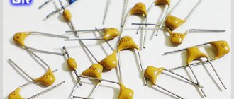
Ceramic
Metal is sprayed onto ceramic plates. Then they are made into packs. Electrodes are formed by metal sputtering. High permeability allows the production of ceramic radio components of very small sizes. Their brands display capacity in micro, - and pico farads.
Air
Airborne radio components are capacitors of variable capacity. The air gap between the moving plates acts as a dielectric. This type of capacitors and their scope are associated with adjusting the frequency characteristics of the current.
Maximum operating voltage on capacitor
All capacitors have some kind of maximum voltage that can be applied to them. The point is that a breakdown of the dielectric may occur and the capacitor will fail. Most often, this voltage is written on the capacitor body itself. For example, on an electrolytic capacitor.
maximum operating voltage of the capacitor
In technical documentation, this parameter is most often designated as WV, which means Working Voltage (operating voltage), or DC WV - Direct Current Working Voltage - constant operating voltage of the capacitor.
There is one nuance here that is often forgotten. The fact is that on the capacitor it is written exactly what direct voltage it is designed for, and not alternating. If a capacitor like the one in the picture above, with a maximum operating voltage of 50 Volts, is inserted into an AC circuit with a power supply that produces 50 Volts AC, your capacitor will explode. Because 50 Volts AC is effective voltage. Its maximum value will be 50 × √2 = 70.7 Volts, which is much more than 50 Volts.
Main settings
The main parameters of capacitors that are used in the design and repair of radio electronics devices are capacitance and rated voltage. In addition, there are several additional parameters that can affect the elements of the circuit. Capacitors have the following main characteristics.
Capacity
This is the most basic parameter that characterizes the accumulation of electrical charge. The value is calculated using various formulas, depending on the design features: flat, cylindrical or round capacitor. In practice, most of them are produced as flat varieties. The capacity of modern devices varies from units of picofarads to tens of thousands of microfarads and even units of farads.
Specific capacity
This relative parameter relates the dimensions to the size of the container. Thus, the higher the specific capacitance, the smaller the dimensions of the structure, however, the electrical strength (operating voltage) may decrease.
Energy Density
This parameter is important when using capacitors as energy storage devices; it determines the amount of energy per unit mass or volume of the element.
Rated voltage
The voltage value at which operating parameters are maintained during the service life is called nominal. The operating voltage must be less than the rated voltage.
Important! Exceeding the rated voltage may result in failure of the element. The electrolytic capacitor may explode in this case. Contrary to popular belief, an element connected to a circuit with a voltage several times less than the nominal voltage retains all other parameters.
Polarity
These types of capacitors, such as electrolytic ones, often require inclusion in a circuit with respect to polarity. Since such elements are used mainly as storage devices or filters, this is not a problem. Failure to comply with polarity leads to:
- capacity mismatch;
- damage.
The marking must contain information about the polarity of the connection.
Risk of destruction (explosion)
Explosive destruction is typical for electrolytic capacitors. The cause of the explosion is heating, which occurs due to:
- non-compliance with polarity;
- location near heat sources;
- aging (increased leakage and increased equivalent resistance).
To reduce the consequences of destruction, a safety valve is installed at the end of the body or notches are formed on the lid. This design ensures that with a sharp increase in pressure inside the housing, accumulated gases and electrolyte are released through a valve or a cap broken along the notches. This prevents an explosion, in which the plates and electrolyte are scattered over a large area and cause short-circuiting of the board elements. Cooling the device reduces the likelihood of destruction.
Consequences of destruction
Capacitor leakage current
The point is that no matter what the dielectric is, the capacitor will still discharge sooner or later, since, oddly enough, current still flows through the dielectric. The magnitude of this current is also different for different capacitors. Electrolytic capacitors have the highest leakage current.
Also, the leakage current depends on the voltage between the capacitor plates. Ohm's law already works here: I=U/Rdielectric. Therefore, you should never apply a voltage greater than the maximum operating voltage specified in the datasheet or on the capacitor itself.
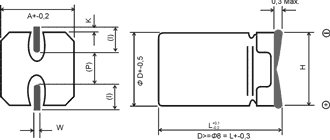
Design Features
A design feature of electrolytic capacitors (EC) is that, despite its small size, the storage device has a fairly large capacity. A dielectric is placed between the electrolyte and the metal element. As a result, a potential arises at the poles of the EC.
The main characteristic of a capacitor is its capacity, measured in microfarads. EC are designed for circuits with low currents.
The aluminum foil tape and paper are rolled into a tight roll. The paper is pre-impregnated with electrolyte. The capacitor looks like a twisted roll enclosed in a cylindrical aluminum housing.
EC design
The negative terminal is soldered to a clean surface of the foil. The positive wire is cold welded to the oxide film (dielectric) that forms on the aluminum.
At the ends of the terminals, contactors are cold welded and soldered into the electrical circuit board. Contacts are designated by “+” and “-” signs. Electric storage devices of this type are called polar.
Non-polar capacitors
Non-polar capacitors include capacitors for which polarity is unimportant. Such capacitors are symmetrical. The designation of non-polar capacitors on electrical circuits looks like this.
capacitor designation in the diagram
Variable capacitors
These types of capacitors have an air dielectric and can change their capacitance under the influence of an external force, such as a human hand. Below in the photo are Soviet types of such variable capacitors.
variable capacitors
The modern ones look a little prettier
trimmer capacitors
A variable capacitor differs from a trimmer only in that the variable capacitor is turned more often than a trimmer. They turn the trimmer once in a lifetime)
In the diagrams they are designated as follows.
variable capacitor designation on the diagram
On the left is variable, on the right is tuning.
Film capacitors
Film capacitors are the most common of the large family of capacitors. They are named so because instead of a dielectric, a thin film is used here, which can consist of polyester, polypropylene, polycarbonate, Teflon and much more. Such capacitors range from a nominal value of 5 pF to 100 µF. They can be made according to the burger principle
And also according to the principle of roll
Let's look at the K73-9 Soviet film capacitor.
K73-9 Soviet capacitor
What's inside? Let's see.
As expected, a roll of foil with a dielectric film
what's inside a capacitor
Ceramic capacitors
Ceramic capacitors are capacitors that are made of ceramic or porcelain that are plated with silver. Take a square or round disk, spray silver on both sides, draw out the leads and voila! The capacitor is ready! That is, there is the simplest flat capacitor, which we talked about earlier in this article.
Would you like to get more capacity? No problem! Put the discs in a sandwich and increase the capacity
Ceramic capacitors may look like this:
ceramic capacitors
ceramic teardrop capacitors
SMD capacitors
SMD capacitors are ceramic capacitors that are built like a sandwich.
structure of SMD capacitor
They are used in microelectronics because they are tiny in size and easy to industrially produce using robots that automatically place SMD components on the board. You can easily find this type of capacitor on the boards of your mobile phones, on computer motherboards, as well as in modern gadgets.
Marking
A letter system was used to label domestic products. Today digital marking is common. The following symbols were used in the alphabetic system:
- K – capacitor;
- B, K, S, E, etc. – type of dielectric, for example: K – ceramic, E – electrolytic;
- In third place was a symbol indicating performance features.
In this marking system, the first letter was sometimes omitted.
In the new marking system, the letter K may appear first, followed by an alphanumeric code. Numbers are used to indicate the denomination, type of dielectric and development number. An example of such marking is shown in Figure 8. Please note that the switching polarity is indicated on the body of the electrolytic capacitor.
- Capacitance from 0 to 999 pF is indicated in picofarads, for example: 250p:
- from 1000 to 999999 pF – in nanofarads: n180;
- from 1 to 999 μF – in microfarads: 2μ5;
- from 1000 to 999999 µF – in millifarads: m150;
- Capacitance greater than 999999 μF is indicated in farads.
Polar capacitors
For polar capacitors, it is very important not to confuse the leads during installation. The positive leg should be connected to the plus in the diagram, and the negative leg to the minus. Polar capacitors are designated in the same way as their counterparts. The only difference is the indication of the polarity of such a capacitor. They may look like this on the diagrams.
designation of polar capacitors in the diagram
Electrolytic capacitors
Electrolytic capacitors are used in electronics and electrical engineering where large capacitance values are required. The name “electrolytes” also came into use.
electrolytic capacitors
The structure of electrolytic capacitors is very similar to film capacitors, which are also assembled according to the roll principle, but with only one difference. Instead of a dielectric, aluminum oxide is used here.
structure of an electrolytic capacitor
Let's take a look at one of these electrolytic capacitors for the sake of science.
We remove its body and see the same roll
We unwind the “roll” and see that between two layers of metal foil we have paper soaked in some kind of solution.
what's inside an electrolytic capacitor
Some people mistakenly believe that paper is the same dielectric, although this is completely wrong. How can it be a dielectric if it is soaked in a solution that conducts electric current?
In fact, the dielectric in this case is a thin layer of aluminum oxide, which is produced electrochemically in production. It all looks something like this:
diagram of the structure of an electrolytic capacitor
The aluminum oxide layer is so thin that it is possible to produce capacitors of enormous capacity with small dimensions. You haven't forgotten the capacitance formula for a flat-plate capacitor, have you?
where d is the same layer of aluminum oxide. The thinner it is, the greater the capacity.
On polar capacitors you can often see this arrow icon, which indicates the negative terminal of the capacitor.
designation of the negative terminal of an electrolytic capacitor
That is, in electrical circuits with direct current, you must strictly follow the rule: plus for plus, and minus for minus. If you mix it up, the capacitor may blow.
Tantalum capacitors
Tantalum capacitors are available in both wet and dry versions. Although, in dry form they are much more common. Here tantalum oxide is used as a dielectric. Tantalum oxide has better properties compared to aluminum oxide. If the biggest disadvantage of electrolytic capacitors is their high leakage current, then tantalum capacitors do not have this disadvantage. The disadvantage of tantalum capacitors is that they are designed for a lower voltage than their electrolytes. Tantalum capacitors are also polar, like electrolytic capacitors.
Tantalum capacitors may look like this
tantalum capacitors
or like this
drop tantalum capacitors
Ionistors
There is also a special class of capacitors - ionistors. Sometimes they are also called supercapacitors or gold capacitors. No, not because there is gold there. The very principle of operation of the ionistor is more valuable than gold. In order to obtain maximum capacity, we must spread the “condensed milk” (dielectric) with a thin, thin layer or increase the area of the pancakes (metal plates). Since it is very expensive to endlessly increase the layer of pancakes, the developers decided to reduce the dielectric layer. Since the dielectric layer between the plates of the ionistor, that is, the “condensed milk layer,” is 5-10 nanometers, therefore the capacitance of the ionistor reaches impressive values! Just imagine what kind of charge such a supercapacitor can accumulate!
The capacity of such capacitors can reach up to ten farads. Believe me, this is a lot. Capacitors look like regular tablets and can also look like cylindrical capacitors. In order to distinguish them from capacitors, just look at the capacitance that is indicated on them. If there are units of Farad, then this is definitely an ionistor!
ionistor large ionistor
Currently, ionistors have become very widely used in electronics and electrical engineering. They replace small batteries with low voltage, because the ionistor cannot yet be designed for a voltage of more than a few volts. But you can connect them in series and dial in the required voltage. But the pleasure is not cheap :-).
They also charge very quickly as their resistance is limited only by their leads. And based on Ohm’s law, the lower the resistance of the conductor, the greater the current flowing through it and, therefore, the faster the ionistor charges. The ionistors can be charged and discharged almost endlessly.
Classification
The main parameters of capacitor products are determined by the type of dielectric. The stability of the capacitance, the dielectric loss tangent, the piezoelectric effect and others depend on the material. Based on this, it is advisable to classify models according to the type of dielectric.
Based on this feature, the following types of products are distinguished:
- vacuum;
- with air dielectric;
- radioelements in which the dielectric is liquid;
- with a solid inorganic dielectric (glass, mica, ceramics). Characterized by low leakage current;
- models with paper dielectric and combined, paper-film;
- DC oil capacitors;
- electrolytic;
- category of oxide capacitors, which include oxide semiconductor and tantalum capacitors;
- solid-state, in which an organic polymer or polymerized semiconductor is used instead of a liquid electrolyte.
In solid-state models, the service life is longer than that of liquid electrolytic models and is about 50,000 hours. They have less internal resistance, that is, the ESR is almost independent of temperature, they do not explode.
Products are also classified according to another important parameter - change in capacity. Based on this feature they distinguish:
- permanent capacitors, that is, those that have a constant capacitance;
- variables in which the change in capacitance can be controlled mechanically or using applied voltage (varicaps and variconds), as well as by changing temperature (thermal capacitors);
- a class of tuning capacitors that are used to adjust or equalize working capacitances when setting up circuits, as well as for the purpose of periodically adjusting various circuits.
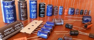
All existing capacitors can be divided into general and special. General purpose products include the most common low-voltage capacitors (see Fig. 6). There are no special requirements for them.
Rice. 6. General purpose capacitors
All other capacitive radioelements belong to the special purpose class:
- pulse;
- launchers;
- high voltage (see Fig. 7);
- interference suppression
- dosimetric, etc.;
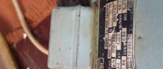
Rice.
7. High-voltage capacitors The devices shown in the photo can operate in high-voltage circuits of relatively low frequency.
Capacitor in DC circuit
So, we take a constant voltage power supply and set the voltage on its crocodiles to 12 Volts. We also take a 12 Volt light bulb. Now we insert a capacitor into the open circuit.
No, the light is not on.
But if you exclude the capacitor from the circuit and connect it directly to the light bulb, then the lamp lights up.
This suggests a conclusion: direct current does not flow through the capacitor! That is, in a direct current circuit, an ideal capacitor has an infinitely large resistance.
To be honest, at the very initial moment of applying voltage, the current still flows for a few seconds. It all depends on the capacitance of the capacitor.
By voltage range
The operating voltage range is a very important characteristic of a capacitor. In electronic circuits, voltages are usually small. The upper limit is about 100 volts. But power supply circuits, various power supplies, rectifiers, device stabilizers require the installation of capacitors that could withstand voltages up to 400–500 volts - taking into account possible surges, and even up to 1000 volts.
But in electricity transmission networks the voltages are much higher. There are high-voltage capacitors of special design.
Using a capacitor outside its voltage range risks breakdown. After a breakdown, the device becomes simply a conductor and ceases to perform its functions. This is especially dangerous where a capacitor is installed to decouple circuits by current, separating the DC voltage from the AC component. In this case, a breakdown threatens that part of the circuit where constant voltage will then flow: other elements may burn, and there may be an electric shock. For electrolytic capacitors, this phenomenon also threatens an explosion.
High voltage capacitors
Left – up to 35 kV, right – up to 4 kV
Since breakdown at high voltage requires a certain minimum distance between conductors, devices for high-voltage versions are usually made of significant size. Or they are made of certain breakdown-resistant materials: ceramic and... metal-paper. Of course, everything is in a housing that has the appropriate properties.
Capacitor in AC circuit
In order to find out how a capacitor behaves in an alternating current circuit, we need to assemble a simple circuit, which is a voltage divider. The meaning of the experiment is this: using a frequency generator, we will change only the frequency, and leave the amplitude unchanged. Essentially, the red dot will show us the signal from the frequency generator, and the yellow dot will show us the signal on the resistor. By taking a signal from a resistor, we can indirectly find out how the capacitor behaves based on the laws of the voltage divider.
Types of cases
What types of tantalum capacitors are there? Types of tantalum capacitors are distinguished depending on the housing material.
- SMD housing. To make packaged devices that are used in surface mount applications, the cathode is connected to the terminal using a silver-filled epoxy resin. The anode is welded to the electrode, and the stringer is cut off. After the device is formed, printed markings are applied to it. It contains an indicator of the nominal voltage capacitance.
- When forming this type of housing device, the anode conductor must be welded to the anode terminal itself and then cut from the stringer. In this case, the cathode terminal is soldered to the base of the capacitor. Next, the capacitor is filled with epoxy and dried. As in the first case, it is marked
Capacitors of the first type are more reliable. But all types of tantalum capacitors can be used:
- in mechanical engineering;
- computers and computing technology;
- equipment for television broadcasting;
- household electrical appliances;
- various power supplies for motherboards, processors, etc.
Capacitor resistance formula
Using physical and mathematical transformations, physicists and mathematicians have derived a formula for calculating the resistance of a capacitor. Please love and respect:
where XC is the resistance of the capacitor, Ohm
P is a constant and equals approximately 3.14
F - frequency, measured in Hertz
C - capacitance, measured in Farads
So, put the frequency in this formula at zero Hertz. A frequency of zero Hertz is direct current. What will happen? 1/0=infinity or very high resistance. In short, a broken circuit.
Air Cooling Devices
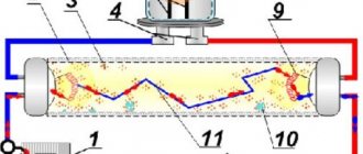
An air-cooled water-cooled condenser consists of several components. Its design includes:
- heat exchanger;
- fan;
- electric motor
To make a heat exchanger, metal tubes with a diameter of 6 or 19 mm are often used. Their fins with a pitch of 1.5–3 mm have a beneficial effect on the operation of the system. Copper is used as the main material, which has high thermal conductivity. The fins are aluminum.
The design of the ribs may be different. The exact model is determined by the intended use of the heat exchanger. A rigid aluminum profile with a groove or protrusion will help increase air flow near the fin itself.
And the movement of air in the heat exchanger also has its own characteristics. The most common agent, freon, enters the system from above, where it begins to cool intensively, spreading downward. Having occupied 90% of the useful area of the heat exchanger, freon reaches the usual temperature norm.
Electrical characteristics of aluminum EC
The main characteristics of an aluminum electrolytic capacitor include the following parameters:
- capacity;
- permissible deviations from the nominal value of the capacity;
- reactance;
- design;
- purpose (alternating or direct current);
- sizes.
Based on the article you read, you can get an idea of what types of capacitors there are. Electrolytic storage devices occupy their niche in radio electronics and electrical engineering. Simplicity of design and low cost contribute to the great popularity of these radio components.