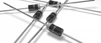
Diodes are the simplest semiconductors with two electrodes that conduct current in one direction.
They are capable of stabilizing, rectifying, modulating, limiting, and converting current, therefore they are installed in almost all household electrical appliances.
The main characteristics of the diode: constant forward and reverse electric current, forward and reverse voltage, forward and reverse resistance, their maximum permissible values.
When installing in any device, the maximum permissible parameter values are taken into account.
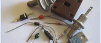
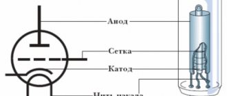
Device
The following is installed in a housing made in the form of a vacuum cylinder made of ceramic, glass or metal:
- crystal;
- anode;
- cathode;
- heater.
Crystals are made from silicon or germanium. The anode (plus) and cathode (minus) are cylindrical in shape and placed inside the cylinder. A heater is a filament inside the cathode that heats up when an electric current is applied, heating it. After reaching a certain temperature level, the active layer on the cathode generates the electrons necessary for operation.
Types of LEDs
- Through-hole LEDs: These are available in a variety of shapes and sizes, and the most common are 3mm, 5mm, and 8mm LEDs. These LEDs are available in various colors such as red, blue, yellow, green, white, etc.
- SMD LEDs (Surface Mount LEDs): Surface Mount LEDs are special packaging that can be easily installed on a PCB. SMD LEDs typically vary depending on their physical dimensions. For example, the most common SMD LEDs are 3528 and 5050.
Bi-color LEDs. The next type of LED is bi-color LED, as the name suggests, it can emit two colors. Bi-color LEDs have three terminals, usually two anodes and a common cathode. Depending on the wire configuration, the color will be activated.
RGB LED (Red - Blue - Green): RGB LEDs are the most loved and popular among hobbyists and designers. Even computer assemblies are very popular for implementing RGB LEDs in computer cases, motherboards, RAM and so on.
High Power LEDs: An LED with a power rating greater than or equal to 1W is called a high power LED. This is because normal LEDs have a power dissipation of several milliwatts. High-power LEDs are very bright and are often used in flashlights, car headlights, floodlights and so on.
Areas of application and purpose
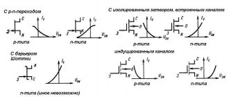
According to the work performed, diodes are divided into universal, microwave, pulse, rectifier, switching, zener diodes, varicaps.
They are installed in electrical equipment:
- frequency converters, detectors, logarithmators;
- current rectifiers;
- stabilizers;
- voltage fluctuation limiters;
- switches;
- circuits that conduct current in a single direction;
- indicator lights;
- devices that require information to be displayed on displays;
- LED TVs.
Reference! LEDs are mounted in lighting matrices (strips, lamps).
How to determine current parameters for an LED: methods, calculation examples
Determining the parameters of an unknown LED can be done in various ways, based on one or another technique. Some of them are purely mathematical, obtained through calculations based on the data obtained. Other options involve measuring the characteristics of LEDs using special instruments (testers or multimeters).
Why do you need to know the current?
Information about how much current a given LED consumes will allow you to avoid overloads or disruption of the operating mode when operating the lamps. A slight decrease in voltage helps to extend the service life, but exceeding the parameters sharply accelerates the failure of individual elements or the entire circuit.
If you are assembling a circuit from a large number of lamps, be sure to measure the current strength and compare the obtained value with the passport data. If the specified 20 mA is exceeded, it is necessary to increase the damping resistance (select resistors with a higher value). If the current in the circuit turns out to be slightly less (about 18 mA), then nothing needs to be corrected. This value will not significantly reduce the brightness of the glow, but will soften the operating mode and increase the service life of the lamps.
Methods for determining current, voltage and other parameters
Not everyone knows how to determine the current and other parameters of an unknown LED. There are different options that require certain knowledge and practical training, or simply the presence of a measuring device. The accuracy and correctness of testing the device depends on the methodology used. Users usually resort to the simplest and most accessible method for determining performance characteristics, although this may not be the most effective. The following options are known:
- measurement with special devices (multimeter);
- calculation of parameters using theoretical techniques;
- visual identification of LED type.
The choice of one or another type of verification is determined by the capabilities and level of training of the user. Let's take a closer look at them.
Multimeter
There are two main operating parameters to be measured by the tester:
- operating current;
- forward voltage drop.
It is necessary to correctly identify the anode and cathode. Elements of a conventional design (with long legs) have a longer anode. On parts soldered into the circuit, the test is performed by sequentially changing the polarity, if it was not determined correctly the first time. On the multimeter, the switch is set to the appropriate position:
- DCV - DC voltage measurement;
- DCA - DC current measurement up to 200 mA.
The tester's readings provide fairly accurate data, limited only by the inherent error of the device. The value of this method lies in the direct measurement of the device under specific conditions. The data displayed on the display allows you to draw conclusions about the operating mode and state of both the LED itself and the entire circuit.
According to Ohm's law
The theoretical method for determining parameters is convenient in that it allows you to do without the use of instruments and determine how many volts are in the LED purely by calculation. The check consists of calculating the parameters using the well-known formula:
Or, more simply, voltage is equal to current times resistance.
By appearance
Visual determination of parameters is a very dubious exercise, giving a minimal and not always correct concept. However, in situations with LEDs, external signs can sometimes provide quite reliable information.
For example, a blue tint in a working element indicates that the supply voltage is too high. The forward voltage drop of LEDs is usually within certain limits that provide a given element color.
A change in mode may indicate the absence (or short circuit) of a quenching resistor in the circuit.
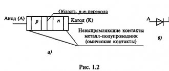
Diode operation and its current-voltage characteristic
By design, a diode is a crystal with two regions with different conductivities (p and n). The region with p-conductivity is the anode (+), with n-conductivity - the cathode (-). In the anode the charge is in holes, in the cathode - in electrons. The crystal is covered with metal with leads.
The structure defines 2 provisions:
- open;
- closed.
In the open position, the conductivity of the electric current is good, in the closed position it is very poor.
The current-voltage characteristic is called a graph. The vertical axis reflects the main and opposite current, and the horizontal axis reflects the main and opposite voltage.
The forward electric current increases rapidly in parallel with the increase in voltage. The opposite current increases more slowly.
When the forward electric current is too high, the crystal molecules heat up. If there is no cooling system, there is a possibility of destruction of the crystal lattice. In circuits, forward flux is limited by a resistor connected in series.
Reference! Direct voltage does not depend on electric current. For silicon semiconductors it does not exceed 1.5 V, for products made from germanium - 1 V.
Checking diodes with a multimeter
For both hobbyists and electronics professionals, a very important skill is the ability to determine the polarity (where is the cathode and where is the anode) and the performance of the diode.
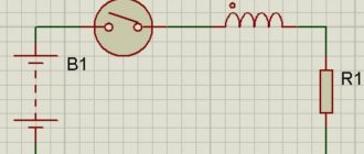
Since we know that a diode is essentially nothing more than a one-way valve for electricity, we can probably test its one-way nature using a DC ohmmeter (battery powered) as shown in the figure below .
When connecting the diode one way, the multimeter should show very low resistance in figure (a). If you connect the diode in another way, the multimeter should show a very high resistance in figure (b) (some models of digital multimeters show “OL” in this case).
Determining Diode Polarity: (a) Low resistance indicates forward bias, the black probe is connected to the cathode and the red probe is connected to the anode. (b) Reversing the probes shows high resistance, indicating reverse bias.
Of course, to determine which diode terminal is the cathode and which is the anode, you must know exactly which terminal of the multimeter is positive (+) and which is negative (-) when it is set to "resistance" or "Ω" mode. .
Most DMMs I've seen use the red lead as positive and the black lead as negative, following electronics color-coding conventions.
One of the problems with using an ohmmeter to test a diode is that we only have a qualitative reading, not a quantitative one. In other words, the ohmmeter only tells you in which direction the diode is conducting current; The low resistance value obtained from the measurement is useless.
If the ohmmeter reads "1.73 ohms" when the diode is forward biased, then the number 1.7 ohms does not provide us as technicians or circuit designers with any really useful quantification.
It represents neither the forward voltage drop nor the resistance value of the semiconductor material of the diode itself; this number rather depends on both quantities and will vary depending on the specific ohmmeter used for the measurement.
For this reason, some DMM manufacturers equip their meters with a special "diode test" function that shows the actual forward voltage drop across the diode in volts rather than the "resistance" value in ohms. These meters work by passing a small current through a diode and measuring the voltage drop between two test leads (picture below).
A multimeter with the Diode Test function shows a forward voltage drop of 0.548 volts instead of low resistance.
The forward voltage reading obtained in this manner using a multimeter is usually less than the "normal" drop of 0.7 volts for silicon diodes and 0.3 volts for germanium diodes, since the current provided by the meter is quite small. If you do not have a multimeter with a diode test function, or you would like to measure the forward voltage drop across a diode at a different current, then you can assemble a circuit from a battery, a resistor and a voltmeter.
Measuring the forward voltage of a diode using a multimeter without the "diode test" function: (a) Circuit diagram. (b) Connection diagram
Connecting the diode in reverse in this test circuit will simply cause the voltmeter to read full battery voltage.
If this circuit was designed to allow a constant (or nearly) amount of current to flow through the diode despite changes in the forward voltage drop, then it could be used as the basis for an instrument that measures temperature: the voltage measured across the diode will be inversely proportional to the diode's junction temperature. Of course, the current through the diode must be minimal to prevent self-heating (a significant amount of power dissipated by the diode), which could interfere with temperature measurements.
Be aware that some DMMs equipped with a "diode test" function, when operating in normal "resistance" (Ω) mode, may produce a very low test voltage (less than 0.3 volts), too low to completely collapse (compress) the PN depletion region transition.
The bottom line is that when testing semiconductor devices, the “diode test” function should be used here, and the “resistance” function should be used for everything else.
Using a very low test voltage to measure resistance makes it easier to measure the resistance of non-semiconductor components connected to semiconductor components, since the junctions of the semiconductor component will not be forward biased by such low voltages.
Consider an example of a resistor and diode connected in parallel and soldered to a printed circuit board. Typically, before measuring the resistance of a resistor, it would be necessary to desolder it from the circuit (disconnect the resistor from the remaining components), otherwise any components connected in parallel would affect the readings obtained.
When using a multimeter that outputs a very low test voltage to the probes in "resistance" mode, the diode's PN junction will not have enough voltage applied to it to be forward biased, and therefore the diode will pass negligible current.
Diode reverse connection
If the plus of the power supply is connected to the minus of the semiconductor, and the minus to the plus, the operation of the diode stops (it closes). Charged particles begin to move away from the pn region, it expands, and the resistance increases
As the reverse voltage increases to 100 V, the electric current increases in the opposite direction. The growth increases sharply if the voltage exceeds the maximum permissible for the pn boundary. The reverse current heats the crystal in the diode, the junction breaks through, and normal operation of the device stops. After turning off the voltage, diffusion occurs near the poles.
Attention! During normal operation, the opposing electric current is small, so it is neglected, considering the semiconductor diode to be a one-way conducting element.
Advantages
In a short amount of time, super-bright and other diodes have become quite popular and in demand in various fields. The reason lies precisely in the advantages, which we will now consider.
- Energy efficient products. Among all available light sources, this type is considered the most economical. Typically, the use of diodes can reduce electricity demands by up to 80%. The ultra-bright white LED consumes the most compared to the others.
- The product can work for a long time without requiring special maintenance or preventive inspection.
- The diode is not very selective with regard to temperature conditions. Therefore, it can be used in any conditions.
- If you need a light source that is protected from moisture and can withstand impacts, then there are such models among super-bright diodes.
- The product does not heat up during operation. The only thing you need to keep an eye on is the power supply. It is he who takes the entire load and heats up.
Forward and reverse voltage
During operation (in the open state), the main voltage in the diode depends on its value and the resistance and magnitude of the electric current. During the closing process, a current passes through the semiconductor in the opposite direction, creating a voltage that contributes to an increase in resistance to several thousand kOhms.
If a semiconductor operates on alternating voltage, it opens on the positive half-wave and closes on the negative half-wave. This property allows semiconductors to be used in rectifiers.
Concept of voltage drop (operating)
A light-emitting diode (aka LED) has one important characteristic - operating voltage or drop voltage. This value shows how many volts the voltage will decrease when passing through the LED in a series connection.
For understanding, it’s worth giving a small step-by-step example:
- The diode has a drop of 3.4 V, and the supply voltage is 12 V.
- After powering the first diode, 8.6 V will remain from 12 V (12-3.4 = 8.6).
- On the second, another 3.4 V will be lost, and 5.2 V will remain (8.6-3.4 = 5.2).
- After the third we get 1.8 V (5.2-3.4 = 1.8).
The final value is less than the voltage drop of the light-emitting diode, which means that it will not be possible to power more of them.
The operating voltage is influenced by the material from which the LED is made. According to operating voltage they are divided into:
- LED with voltage from 3 V to 3.8 V: blue, white, blue-green.
- LED with voltage from 1.8 V to 2.1 V: red, yellow, orange, green.
Basic diode faults
Attention! If diode semiconductors stop working, you first need to find out whether their service life has expired.
If this is not the case, another reason caused the malfunction:
- violation of tightness;
- a junction gap that turned the device into an insulator:
- thermal breakdown;
- electrical breakdown:
- tunnel;
- avalanche
If the seal is broken, a leak occurs, interfering with normal functioning.
Breakdown of pn transition
A breakdown is an increase in electric current in the opposite direction after reaching the reverse voltage during operation, which is the maximum permissible for the device. If it is exceeded, the opposite flow of electric current increases sharply with a slight change in voltage. After the transition breaks, there is only one direction of flow, the semiconductor turns into a conductor.
How many volts are there?
The operating voltage of an LED can be determined not only by its appearance and characteristics, but also by the color glow of the LED. To do this, check out the table below.
| LED color | Voltage, V |
| Red | 1,63 ― 2,03 |
| Yellow | 2,1 ― 2,18 |
| Green | 1,9 ― 4,0 |
| Blue | 2,48 ― 3,7 |
| Orange | 2,03 ― 2,1 |
| Infrared | up to 1.9 |
| Violet | 2,76 ― 4 |
| White | 3,5 |
| UV | 3,1 ― 4,4 |
How color affects brightness
To understand this aspect, you need to know what happens inside the diode and what affects the color type.
The internal structure of a semiconductor LED consists of two semiconductors designed for different levels of conductivity. An electric current passes through the first semiconductor due to a physical phenomenon that ensures the movement of free electrons. Current moves through the second conductor due to the movement of “holes”.
A “hole” is a place where an electron is missing.
At the junction of semiconductors, the stage of recombination of “holes” and electrons begins. An electron flies to the place of the “hole”, which makes the atom neutral - a photon is emitted, that is, color appears.
Color can change if it is influenced by the following factors:
- what type of semiconductor the LED was made from;
- what impurities were used at the points of contact between two semiconductors;
- width of the forbidden zone (recombination site);
- parameters and magnitude that influence the current strength in a section of the electrical circuit.
The color change occurs due to an increase or decrease in electrical current. When referring to Ohm's law, it must be remembered that the higher the voltage, the greater the current. This means that the photon's energy will also increase, thereby moving towards a cooler (blue) and brighter glow.
Main conclusions
Semiconductor diodes are radioelements with a single pn junction, present in almost all household electrical appliances. In order for semiconductors to last longer, it is necessary to have knowledge about the principle of operation of diodes, the causes of malfunctions and ways to prevent them.
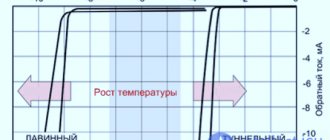
Most often, the operation of semiconductors is disrupted by changes in temperature in the environment or transition. If the temperature is too high, the amount of energy carriers in the junction increases, the resistance decreases, and the volume of opposite current increases. After reaching the maximum permissible level, the process of destruction of the crystal starts.
To prevent a reduction in operating time, it is necessary to monitor the temperature of the environment and the cleanliness of the devices. If necessary, an additional heat removal system should be installed. Temperature increases in the junction are prevented by complying with the voltage and current requirements specified for the specific device. Even at the slightest excess, there is a possibility of crystal destruction.
Technical characteristics of LED strip
When choosing, the consumer takes into account the dimensions of the strip product, power, voltage, type of LEDs, their number per meter, color, cutting capabilities.
Operating voltage
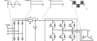
The first LED strips were produced with 12 V drivers. After the advent of powerful chips, 24 and 36 V strips began to be produced to avoid overheating of the printed circuit board and burnout of conductive threads by reducing the current on each chip. Then varieties appeared that operate from the mains through a rectifier, diode bridge and connector.
Type of diodes and number of LEDs per 1 meter
Dependence of power on types of LEDs and quantity on the meter
| LED type | Size(mm) | Number of diodes per meter (pcs.) | LED Power (W) | Power 1 m (W) |
| SMD 3528 | 3.5 x 2.8 | 30 | 0,08 | 2,4 |
| 60 | 4,8 | |||
| 120 | 9,6 | |||
| SMD 5050 | 5 x 5 | 30 | 0,24 | 7,2 |
| 60 | 14,4 | |||
| 120 | 28,8 | |||
| SMD 3014 | 3x1.4 | 60 | 0,1 | 6 |
| 120 | 12 | |||
| 240 | 24 |
Glow color
The RGB+White canvas is two-row, the glow temperature of the white row can reach 6000 Kelvin. White color makes it possible to dilute the glow intensity of RGB diodes to obtain soft pastel shades. This lamp can be used as a source of main lighting if you turn off the RGB row.
White-MIX canvas is ideal for illuminating interior items. Chips with different light temperatures make it possible to make transitions from cold to warm glow. White-D-MIX tape is made from SMD 3528, there are 2 types of phosphors in one chip, the tones are mixed evenly. White-TRIX canvases are distinguished by a white board; channels with cold, daylight and warm light are controlled separately.
SPI (dynamic) tapes are rarely used in everyday life. For them, “Running Fire” controllers are produced, which allow you to create various dynamic color effects. Similar products are chosen for restaurants and bars. Pixel Light RGB strips are connected through controllers that can control each chip. These products are used to create 2D screens to display video effects.
DIP-LED strips are used outdoors to illuminate facades, signs, and vehicles. Based on the principle of operation, blades made of SMD 335 with side radiation are similar to it. For both products, the beam extends parallel to the board, which is convenient for illuminating individual objects.
Base color
The base of any LED strip is covered with glue
If a decorative profile is not used during installation, it is important to choose an LED strip with a base color that matches the color of the interior
There are several types of base:
- transparent;
- white;
- gray;
- brown;
- black.
Security class
Strip LED products with protection class IP20 are suitable for use in heated, dust-free rooms with normal humidity levels.
IP54 and IP65 are afraid of sub-zero temperatures; for outdoor use you need to choose a product marked IP67. IP68 is used to indicate maximum protection. Products with this marking are suitable for bathtubs and fountains, they can even be placed in an aquarium.
Cutting parameters
Cutting lines (scissor icons) are indicated throughout the strip. On a canvas made of SMD 3528, the distance between them is 5 cm, from SMD 5050 - 10 cm.
On tapes powered by 220 V, 60 chips are connected in series. Such a strip can be cut into pieces 50 cm long (if the density is 120 pieces per 1 m) or 1 m (if the density is 60 pieces per 1 m).
Read with this
- Parameters and characteristics of LED 2835 smd led
- Checking the LED strip for functionality. troubleshooting
- Calculation of a resistor for an LED: how to choose a current-limiting element
- Calculation of resistor resistance for LEDs: online calculator
- LED Polarity Determination
- Types, characteristics and features of LED strips
- Resistor resistance
- How to use a multimeter correctly
- Correct choice of current transformer according to GOST
- Calculation of the resistance of parallel connection of resistors
Testing and interchangeability
Schottky rectifiers can be tested in the same way as conventional semiconductors, since they have similar characteristics. You need to ring it in both directions with a multimeter - it should show itself in the same way as a regular diode: anode-cathode, and there should be no leaks. If it shows even a slight resistance - 2-10 kilo-ohms, this is already a reason for suspicion.
Checking a Schottky diode with a multimeter
A diode with a common anode or cathode can be tested like two ordinary semiconductors connected together. For example, if the anode is common, then it will be one leg out of three. We place one tester probe on the anode, the other legs are different diodes, and another probe is placed on them.
Can it be replaced with another type? In some cases, Schottky diodes are replaced with ordinary germanium diodes. For example, D305 at a current of 10 amperes gave a drop of only 0.3 volts, and at currents of 2–3 amperes they can generally be installed without radiators. But the main purpose of the Schottky installation is not a small drop, but a low capacity, so replacement will not always be possible.
As we see, electronics does not stand still, and further applications of high-speed devices will only increase, making it possible to develop new, more complex systems.
Differences from a conventional diode
This component passes electric current in one direction and does not pass it in the other, like other classic diodes, but provides high speed and low voltage drop during transition.
The most important feature of the Schottky diode is that instead of the usual electron-hole junction, the principle of contact between metal and various semiconductor materials is used, which has a positive effect on increasing the operating frequency. Diffuse capacitance and the recombination process do not appear in the contact region, since there are no minority charge carriers in the so-called transition zone. The intrinsic capacity of this layer tends to 0.
Thus, these products are microwave diodes for various purposes:
- pulsed;
- avalanche-flight;
- mixing;
- detector;
- multiplying;
- parametric.
Another feature is that most Schottky diodes are low voltage and static sensitive models. However, it is wrong to perceive this as a categorical disadvantage, since this makes it possible to use these tools for processing low-power radio signals.
Finally, such products are more stable when applying electric current than other analogues, since crystal formations (silicon substrate) are embedded in their body.
Types of Schottky diodes
All semiconductor elements operating on the Schottky barrier principle are divided by power into:
- high;
- average;
- low power.
Dual diode
The figure shows a dual element, which is essentially two elements. They are located in a single housing, connected as a whole by a cathode or anode. In this case, most often there are three diode terminals. With identical parameters of the elements assembled in this way, the reliability of the entire device is ensured, primarily due to a uniform temperature.
What is a Schottky diode
It differs from a conventional diode element in its small voltage drop. In addition to the semiconductor, it contains metal. The name is in honor of the German physicist Walter Schottky, who discovered the so-called Schottky effect.
On a note!
The metal used for a Schottky zener diode can be tungsten carbide, silicon carbide, palladium, platinum, gold, gallium arsenide and others.
Approximate diode models
In most cases, for calculations in electronic circuits, an exact model of the diode with all its characteristics is not used. The nonlinearity of this function makes the problem too complicated. They prefer to use so-called approximate models.
Approximate diode model “ideal diode + Vϒ”
The simplest and most frequently used is the first level approximate model. It consists of an ideal diode and, added to it, the conduction threshold voltage Vϒ.
Advantages and disadvantages
When working with devices that include a Schottky diode, you should consider their positive and negative aspects. If you connect it as an element of an electrical circuit, it will perfectly hold the current, preventing large losses.
In addition, the metal barrier has minimal capacity. This significantly increases the wear resistance and service life of the diode itself. The voltage drop when using it is minimal, and the action occurs very quickly - you just need to make a connection.
However, the large percentage of reverse current is an obvious disadvantage. Since many electrical appliances are highly sensitive, there are often cases when a slight excess of the indicator, just a couple of A, can damage the device for a long time. Also, if you carelessly check the semiconductor voltage, the diode itself may leak.
Schottky diode in RF circuits
Schottky diodes also have fast switching speed. This means we can use them in high frequency (RF) circuits.
So, let's take a frequency generator and set the sine frequency to 60 Hz
Let's take a 1N4007 diode and a 1N5817 Schottky diode. Let's connect them using a simple half-wave rectifier circuit
and we will take evidence from them
As you can see, both of them do an excellent job of rectifying the signal at a frequency of 60 Hz.
But what happens if we increase the frequency to 300 kHz?
Wow! The Schottky diode more or less copes with its task, which cannot be said about a simple 1N4007 diode. A simple diode cannot cope with its task of not allowing reverse current to pass through, so we see a negative surge on the oscillogram
From this we can conclude: Schottky diodes are recommended for use in RF circuits.
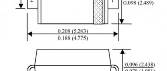
Miniaturization
With the development of microelectronics, special microcircuits and single-chip microprocessors began to be widely used. All this does not exclude the use of hanging elements. However, if radioelements of conventional sizes are used for this purpose, this will negate the whole idea of miniaturization as a whole. Therefore, open-frame elements were developed - SMD components, which are 10 or more times smaller than conventional parts. The current-voltage characteristics of such components are no different from the current-voltage characteristics of conventional devices, and their reduced dimensions make it possible to use such spare parts in various microassemblies.
SMD components come in several sizes. SMD size 1206 is suitable for manual soldering. They have a size of 3.2 by 1.6 mm, which allows you to solder them yourself. Other SMD elements are more miniature, assembled at the factory with special equipment, and it is impossible to solder them yourself at home.
The operating principle of an smd component is also no different from its large counterpart, and if, for example, we consider the current-voltage characteristic of a diode, then it will be equally suitable for semiconductors of any size. The current range is from 1 to 10 amperes. The markings on the case often consist of a digital code, the decoding of which is given in special tables. They can be tested for suitability using a tester, just like their larger counterparts.
Reverse leakage current
But since Schottky diodes are so cool, why not use them everywhere? Why do we still use simple diodes?
If we connect the diode in the opposite direction, it will block the passage of electric current. This is true, but not entirely. Very little current will still flow through the diode. In some cases this is not taken into account. This small current is called reverse leakage current. In English it sounds like reverse leakage current.
It is very small, but it exists.
Let's do a simple experiment. Let's take a laboratory power supply, set it to 19 V and apply this voltage to the diode in the opposite direction
We measure the leakage current
diode reverse leakage current
As you can see, its value is 0.1 µA.
Let's now repeat the same experiment with a Schottky diode
Schottky diode reverse leakage current
Wow, almost 20 µA already! Well, yes, in some cases these are mere pennies and can be ignored. But there are circuits where such a small current is still unacceptable. For example, in peak detector circuits
peak detector circuit
In this case, these 20 µA will be quite significant.
But there is also another stumbling block. As the temperature increases, the reverse leakage current increases significantly!
dependence of the reverse leakage current on the body temperature of the Schottky diode
Therefore, you cannot use Schottky everywhere in the circuits.
But that's not all. The reverse voltage for Schottky diodes is several times less than for simple rectifier diodes. This can also be seen from the datasheet. If the reverse voltage is 1000V for the 1N4007 diode
Then for a 1N5817 Schottky diode this reverse voltage will already be only 20 V
Therefore, if this voltage exceeds the value described in the datasheet, we will end up with: