A transformer is a device that is designed to convert network electricity. This installation has two or more windings. During their operation, transformers can convert the frequency and voltage of the current, as well as the number of phases of the network.
During the performance of specified functions, power losses are observed in the transformer. They affect the initial amount of electricity that the device produces at the output. What are the losses and efficiency of a transformer will be discussed further.
Device and principle of operation
In static equipment, which is designed to convert frequency and voltage, as well as the number of phases, there are no moving structural elements, which eliminates the occurrence of mechanical losses. But in the process of transferring the load from the primary circuit to the secondary, not all the power reaches the energy receiver, which acts as the end consumer.
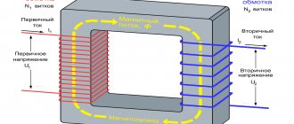
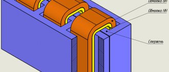
Electromagnetic static equipment without rotating parts converts energy and operates from the mains. The power unit is a device, the main elements of which are a steel magnetic circuit of a rod or armored design and coils - unconnected electrically insulated wires.
Transformer equipment is of single-phase and multi-phase types, respectively, consisting of two or more circuits. Depending on the type of design, devices with armored, rod or armored rod magnetic circuits are distinguished. The operating principle of the equipment using the example of a simple single-phase device:
- The first coil is connected to the alternating current source, and the secondary circuit is connected to the electricity receiver (end consumer).
- Alternating current passes through the turns of the primary winding, and its value corresponds to the value of the load I1.
- The magnetic flux F penetrates both circuits and induces an electromotive force in the conductors.
- When the second circuit is connected to a source of electricity, a load current I2 arises in the circuit under the influence of EMF.
- The transformer unit operates at idle speed if no load is applied to the secondary winding of the device.
Peculiarities
The value of the electromotive force indicator is closely related to the number of turns of wire on the coils. The ratio of the EMF in the windings, called the transformation ratio, corresponds to the number of turns of the copper coils. By changing the number of turns in the circuits, you can regulate the voltage in the electricity receiver.
The windings are interconnected by magnetic lines, and the degree of their interconnection is affected by the proximity/distance of the coils. Due to the change in current strength in the first winding, both circuits are penetrated by a magnetic flux, constantly changing its magnitude and direction. The connection of the ends of the secondary winding with the receiver transmits current to it, and the means of energy transmission is an alternating magnetic flux - the coils are not connected to each other galvanically.
It is also worth considering that you cannot open the secondary winding of the transformer.
On a note! According to the described principle, multiphase transformer units operate, consisting of several step-up and step-down windings and a steel core. The phases of the coils are mainly connected in a star or delta configuration.
Concept of losses
When the installation is operating, part of the power is supplied to the primary circuit. It dissipates in the system. Therefore, the incoming power to the load is determined at a lower level. The difference is the total reduction in power in the transformer.
There are two types of reasons due to which the energy consumption of equipment increases. They are influenced by various factors. They are divided into the following types:
- Magnetic.
- Electrical.
They should be understood in order to be able to reduce electrical losses in the power transformer.
Magnetic losses
In the first case, losses in the steel of the magnetic drive consist of eddy currents and hysteresis. They are directly proportional to the mass of the core and its magnetic induction. The iron itself, from which the magnetic drive is made, affects this characteristic. Therefore, the core is made of electrical steel. The plates are made thin. Between them lies a layer of insulation.
Also, the reduction in power of a transformer device is affected by the frequency of the current. As it increases, magnetic losses also increase. This indicator is not affected by changes in device load.
Electrical losses
A decrease in power can be detected in the windings when they are heated by current. In networks, such costs account for 4-7% of the total energy consumed. They depend on several factors. These include:
- Electrical load of the system.
- Configuration of internal networks, their length and cross-sectional size.
- Operating mode.
- Weighted average power factor of the system.
- Location of compensation devices.
Power losses in transformers are variable. It is influenced by the square of the current in the circuits.
How to calculate
In practice, two main methods are used to calculate losses of electromagnetic equipment, for which the technical characteristics of transformers are used. The Ministry of Energy of the Russian Federation recommended calculating load losses in the reporting period based on the power grid diagram:
ΔWHj= KК *ΔРСС * ТJ * K2Ф, where
ΔРСС – average power losses, kW;
K2Ф – graph shape coefficient;
KK – clarifying parameter (0.99);
ТJ – duration of the billing period.
If there is no load graph, K2F = (1+2KZ) / 3KZ), and if there is no information about the load factor of the graph, KZ = 0.5.
For two-winding
To perform calculations, you need to use the technical (catalog) parameters of the transformer, which include:
- rated power;
- idle losses;
- short circuit costs.
Also for calculations you need calculated data:
- actual energy consumed over a period of time;
- number of hours worked (per month/quarter);
- operating time of the transformer at the rated network load.
After receiving the listed data, the angle cos φ, which acts as the weighted average power factor, is measured, starting from the value of tg φ - the compensation coefficient of the dielectric loss unit:
If the power system does not include a reactive power meter, use the expression:
Formulas
For calculations use the formula:
K = EA / RNOM * POINT * cos φ, where
EA – active electricity;
cos φ = r / Z – phase shift angle (r – active and Z – total resistance of the circuit).
Or this entry:
Accordingly, the losses of the transformer in operating mode (under load, and not during no-load) are calculated as follows:
R = RXX * TOCH * RKZ * K2 * TNC
or this entry:
The described technique is used when calculating losses in double-circuit transformers.
For three-winding
To calculate the loss of electricity in three-winding power units, the calculation formula additionally includes the technical characteristics of the equipment specified by the manufacturer in the passport. Calculation formula:
E = ESN + ENN,
where E is the actual energy consumed;
ESN and ENN, respectively, electricity in medium and low voltage circuits or according to the formula where the coefficients are found as follows:
The formula uses the rated power of each winding circuit and the losses that occur during a short circuit.
Bibliography
- Savintsev Yu. M. “Innovative dry transformer - real energy efficiency.” // "Industrial pages of Siberia". 2022 No. 4-5 (148-149). Page 66-69.
- “Dry power transformers 6-35 kV. Criterias of choice". [Electronic resource]. Access date 05/18/2020.
- “Dry power transformers. Choice, device, characteristics." [Electronic resource]. Access date 05/18/2020.
- Kravchenko A., Metelsky V. “Dry and energy-saving transformers.” [Electronic resource]. Access date 05/18/2020.
- Mikheev G. M., Efremov L. G., Ivanov D. E. “Methods of increasing the energy efficiency of power transformers.” [Electronic resource]. Access date 05/18/2020.
- “Design features, advantages and disadvantages of dry transformers.” [Electronic resource]. Access date 05/18/2020.
- "Standards for losses in transformers." [Electronic resource]. Access date 05/18/2020.
- Vasiliev S. “The future belongs to dry transformers.” [Electronic resource]. Access date 05/18/2020.
- Savintsev Yu.M. “Distribution transformer energy efficiency is a controllable state.” [Electronic resource]. Access date 05/18/2020.
- Kudrin B. I. “Two discoveries: the phenomenon of invariance of the structure of technocenoses and the law of information selection.” / "Technology". 2009 pp. 82.
- Savintsev Yu. M. “Methodology for forecasting market demand for electrical equipment of power supply networks based on the cenological paradigm.” [Electronic resource]. Access date 05/18/2020.
- Savintsev Yu. M. “Basic provisions of the theory of energy efficiency of power transformers.” [Electronic resource]. Access date 05/18/2020.
Author: independent expert, candidate of technical sciences Yuri Mikhailovich Savintsev.
Calculation examples
For a clearer understanding of the calculation methodology, it is convenient to consider the calculation procedure using a specific example. The work involves a power unit with a rated power of 400 kVA and a rated voltage of 10 kV. The task is complicated by the need to calculate the constant and variable losses of the transformer based on active and reactive energy.
Table 1. Initial data
| Index | Expression | Meaning |
| Rated power, kVA | Snom | 400 |
| Rated voltage, based on network parameters 10/0.4, kV | Unom | 10 |
| Transmitted active electricity, kWh | Wa | 53954 |
| Reactive electricity, kWh | Wr | 39062 |
| Short-circuit loss, kW | RKZ | 5,9 |
| Costs in idle mode, kW | RXX | 0,95 |
| Hours worked under load, h | DOT | 696 |
| Maximum load time, h | TM | 333 |
| Time of greatest losses, h | t | 200 |
| Power factor | cos φ | 0,81 |
The device worked for 696 hours in operating mode, and part of the time the transformer operated at maximum load, and part of the time it converted electricity with the greatest losses. To calculate these values, you need to take into account the rule below.
Accordingly, the time of use of the maximum load of the TM is 333 hours, and the time of greatest losses t will be 200 hours.
The power factor is found using the formula:
Constant energy losses depend on idling costs and amount to
∆W0,а = ∆P0 * TOR = 0.95 * 696 = 661.2 kWh
∆W0,r = ∆Q0 x TOCH = 8.346 x 696 = 5808.816 kvarh, where
To calculate variable losses of active energy in the billing period, the formula is used:
∆Ws,a = RKZ * t * ((W2a + W2r) / (T2M * S2nom)) = 5.9 * 200 * ((539542 + 390622) / (3332 * 4002)) = 295.057 kWh;
reactive energy:
∆Ws,r = ΔQsc * t * ((W2a + W2r) / (T2M * S2nom)) = 17.005 * 200 * ((539542 + 390622) / (3332 * 4002)) = 850.502 kWh, where
The total energy losses in the calculation period are:
∆Wa = ∆W0,a + ∆Ws,a = 661.2 + 295.087 = 956 kWh,
∆Wr = ∆W0,r + ∆Ws,r = 5808.816 + 850.502 = 6659 kvarh.
Example result: 956 and 6659.
Standardization of energy efficiency of dry-type distribution transformers
To form a model on the basis of which it is possible to standardize energy efficiency (as noted by the author in a number of works [9, 11 12]), it is necessary to consider not one individual or several transformers, but the entire complex of power/distribution transformers that provide power supply over a vast territory, up to territory of a country or group of countries. And fundamental to all subsequent conclusions is the concept of “energy efficiency” .
- On the quantitative side, “ Energy efficiency is characteristics that reflect the ratio of the beneficial effect from the use of energy resources to the expenditure of energy resources incurred in order to obtain such an effect, in relation to products...”. This is the definition of energy efficiency according to 261-FZ.
- On the substantive side, energy efficiency is the controlled state of a large set of devices, organized for some purpose, which characterizes the ability of this set to change (reduce, reduce) the specific costs of operating a given set of devices. This is the author’s conceptual interpretation of energy efficiency, which forms the basis of the developed theory of energy efficiency of power and distribution transformers.
The normalization of short-circuit and short-circuit losses of dry energy-efficient power/distribution transformers is carried out according to the method described in [9].
For adequate comparison with the results of normalizing losses of oil-fired energy-efficient transformers, the following initial data and simplifications for modeling were adopted:
- In test calculations, to simplify the model, it is assumed that all installed transformers are dry. In the methodology outlined in [9], it is also assumed that all transformers are oil-based. You can complicate the model and consider the entire set of transformers, consisting of two groups: 80% oil-based and 20% dry. This will not significantly affect the calculation results.
- As in [9], the target reduction in GDP energy intensity is taken to be 0.08 t.e.f./million rubles.
A complete list of source data is given in Table 4.
| Table 4. Initial data for calculating the standard short-circuit and short-circuit losses of energy-efficient dry power/distribution transformers. | |
| Index | Meaning |
| Total number of distribution transformers in the Russian Federation, pieces, NΣ | 3 020 649 |
| Total transformer power, MVA, SΣ | 846 472 |
| Total losses (at load equal to 1), kW, PΣ | 10 737 243 |
| Target value for reducing GDP energy intensity, t.e./million rubles, ΔE | 0,08 |
| The value of the total share of losses subject to reduction, kW*hour, ΔWΣ | 21 375 000 000 |
| The value of the total power of losses subject to reduction, kW, ΔPΣ | 2 440 000 |
| Specific value of reduced losses, kW/kVA, ΔPud | 0,002882 |
| Share of losses Kхх in the total power losses, | 0,12726 |
| Share of losses Kkz in the total power losses, | 0,87274 |
The values of the obtained energy-efficient losses xx and short-circuit for each rated power of the entire line of dry-type transformers from 25 to 6300 kVA are given in Table 5.
| Table 5. Estimated energy-efficient standard losses for dry-type transformers with a capacity of 25-6300 kVA | |||||||
| Dry transformer power, kVA | Required reduction in specific power of total losses of dry tr-ditch, W | Estimated standard specific power loss xx, E-EF. dry tr-ditch, W | Specific power loss xx of conventional dry tanks, W | Estimated standard specific power of short-circuit losses, E-EFF. dry tr-ditch, W | Specific power of short-circuit losses of conventional dry tr-ditches, W | Energy intensity coefficient (efficiency) e-eff. dry tr-ditch | Energy efficiency coefficient (COP) of conventional dry-type transformers |
| 25 | 0,0721 | 173,2 | 195 | 399,7 | 450 | 0,9763 | 0,9742 |
| 40 | 0,1153 | 201,5 | 230 | 613,2 | 700 | 0,9799 | 0,9768 |
| 63 | 0,1816 | 257,9 | 290 | 1200,5 | 1350 | 0,9801 | 0,9740 |
| 100 | 0,2883 | 334,0 | 380 | 1757,8 | 2000 | 0,9826 | 0,9762 |
| 160 | 0,4612 | 436,7 | 510 | 2312,1 | 2700 | 0,9853 | 0,9799 |
| 250 | 0,7206 | 515,4 | 620 | 3034,0 | 3650 | 0,9880 | 0,9829 |
| 400 | 1,1530 | 916,2 | 1100 | 4830,8 | 5800 | 0,9874 | 0,9828 |
| 630 | 1,8160 | 1100,9 | 1240 | 5583,1 | 7100 | 0,9906 | 0,9868 |
| 1000 | 2,8826 | 1268,6 | 1600 | 6488,8 | 8900 | 0,9925 | 0,9895 |
| 1600 | 4,6121 | 1864,2 | 2100 | 7323,7 | 11000 | 0,9940 | 0,9918 |
| 2500 | 7,2064 | 2476,9 | 2750 | 13416,7 | 19500 | 0,9941 | 0,9911 |
| 4000 | 11,5302 | 2798,9 | 4000 | 24070,9 | 34400 | 0,9941 | 0,9904 |
| 6300 | 18,1601 | 3510,5 | 5400 | 30229,4 | 46500 | 0,9950 | 0,9918 |
To compare with current energy efficiency standards for transformers, Tables 6, 7, 8 show, respectively, the values of the xx and short-circuit losses of energy-efficient transformers in accordance with Government Decree No. 600 of June 17, 2015, STO standard 34.01-3.2-011-2017 and Council of Europe resolution No. 548/2014 dated May 21, 2014
As can be seen from a comparison of the calculation results using the new methodology for normalizing loss indicators of dry energy-efficient transformers, the data obtained, as expected, do not coincide with the loss indicators of regulatory documents. Thus, the obtained values of losses xx and short-circuit for a transformer with a power of 1000 kVA are, respectively, 1270 W and 6500 W; standard values are 1600 and 8900 W. The normative document “Resolution No. 600” requires for this transformer power values of xx losses 1100 W and short-circuit losses 10500 W. The requirements of the European standard are for xx losses 1550 W and for short-circuit losses 9000 W.
If we proceed from the requirements for reducing an intuitive and logically transparent indicator, the scientific criterion of GDP energy intensity, we will see that the requirements for energy efficiency of transformers are manageable and should be justified more flexibly than defined by current regulatory documents.
The author expresses sincere gratitude to the management and leading specialists of Transformer LLC for the numerous technical and other data provided on distribution transformers, as well as for the constructive discussion of the abstracts of the article.
Measuring efficiency
Operation of the equipment with the secondary circuit open is called idling, and with the load current connected - operating mode. In the first circuit of the circuit, the flow F0 creates a self-inductive emf, and when the secondary circuit is open, it balances part of the voltage. By transferring a load to the secondary winding, it is possible to cause the formation of a current I2, which excites its own flux F2. The total magnetic flux decreases, reducing the magnitude of the emf E1, and some part of U1 remains unbalanced.
At the same time, I1 increases and increases until the demagnetizing effect of the load current ceases. This helps restore F0 to approximately its original value.
The conductor of the secondary winding naturally has active resistance. If it increases, I2 and Ф2 decrease, causing an increase in Ф0 and an increase in emf E1. As a result, the balance between U1 and EMF E2 is disrupted - the difference between them decreases, reducing I2 to a value at which the total magnetic flux returns to its original value.
Calculation method
This process contributes to almost complete constancy of the magnetic flux values during operation of the transformer at idle and in operating mode. This property of the energy converter is called self-regulating ability, due to which the value of the load current I1 is automatically adjusted when the load current I2 fluctuates.
The process of converting electricity in transformer units is accompanied by losses and is reflected in the value of efficiency, which is the ratio of the supplied active power to the consumed one. The efficiency indicator reflects the ratio of active power at the input and output for a closed circuit. It is calculated using a simple formula:
Efficiency = (M1 / M2) * 100% or
ƞ = (P2 / P1) * 100%, where the active power in the windings of the input and output circuits is determined by measurement.
The measurement process can be simplified by connecting the active load current to the secondary winding. To determine the value of M2, use an ammeter connected to the secondary circuit. The dissipation flux will be insignificant, which allows us to approximately equate cos φ squared to unity.
This method of calculating efficiency is a direct measurement method. This theory of calculations leads to errors in calculations, since the efficiency of high-power transformers is very high and amounts to 0.98-0.99%. Despite the fact that the values of M1 and M2 differ insignificantly, in industrial equipment a slight difference in readings causes a significant distortion of the efficiency value.
To avoid errors, in practice, when measuring the efficiency of transformers, two methods are used: no-load test and short-circuit test.
The meaning of the first method is to supply the rated voltage to the primary circuit with the secondary circuit open. Energy is spent on losses in steel, the power of which can be measured with a wattmeter connected to the primary winding circuit.
Another method is to short-circuit the secondary circuit and simultaneously apply voltage to the primary circuit. Including a wattmeter in the first circuit allows you to measure the power, which reflects the loss of the copper conductor of the winding.
Three-phase transformers
Magnetic systems of three-phase transformers
The main types of magnetic systems of three-phase transformers, depending on the structural design of the magnetic circuit:
— Rod magnetic system;
— Armor magnetic system;
— Armored rod magnetic system.
Also (depending on the relationship between the flows of various phases) magnetic systems are divided as:
— Independent;
— Partially connected;
— Connected magnetic system.
We will show the most common types of three-phase transformers.
Independent magnetic system.
Three-phase transformer group.
This type is shown in Fig. 2.28. A three-phase transformer group is obtained from three single-phase transformers, the windings of which are connected
in a certain way. The winding connection diagram in the figure is star/star (U/U).
Used only at very high powers (more than 10 MVA per phase). This type has some advantages during transportation and installation. Thus, if one single-phase transformer fails, only one single-phase transformer must be repaired or replaced.
The disadvantages include the bulkiness of the entire structure, increased dimensions and weight, hence the increased cost.
They are used, for example, in metallurgy to ensure the operation of powerful electric arc furnaces.
Three-phase armor transformer.
A three-phase armor transformer can be considered as three single-phase armor transformers stacked on top of each other. A three-phase armored transformer is shown in Fig. 2.29.
The middle phase has reverse switching compared to the outer phases, so that the flows in the yokes are summed up. The vector diagram of the flows in the yoke is shown in Fig. 2.30. They are used quite rarely due to the relative complexity of the design.
Armored rod transformer.
In order to reduce the height of the magnetic circuit structure, armored rod type transformers are made (Fig. 2.31).
Three-rod transformer
If a symmetrical system of three-phase voltages is supplied to the primary winding, then symmetrical systems of currents flow through the windings, therefore, the flows of the three phases also form a symmetrical system, then
. (2.98)
Then this combined rod can be removed (Fig. 2.32, b). The transformer obtained in this way can be made more compact by placing all three rods in one plane (Fig. 2.32, c). The resulting transformer is called a three-phase core transformer, or three-rod. Due to the decrease in the length of the magnetic circuit through which the flow of phase B is closed, some magnetic phase asymmetry arises, which is usually small and will only affect the no-load mode, in particular, the no-load current, which will be less in the middle phase than in the extreme ones.
However, as was shown earlier (Sections 2.4, 2.5), when under load, the no-load current has little effect on the current values of the primary and secondary windings. Thus, we can assume that with a symmetrical supply voltage and load, all phases of a three-phase transformer are in the same conditions. Therefore, for each phase, the complex equations, vector diagrams and equivalent circuits derived earlier are valid. The only exception is the idle mode, which is affected by the winding connection diagram. The structural design of a three-phase core transformer is shown in Fig. 2.33.
Calculator
To simplify calculations, it is convenient to use an online calculator. The program algorithm allows you to calculate the energy losses of a transformer without complex formulas. But the results obtained should be considered as indicative. The following data is used to enter:
- the value Snom (kVA) is taken from the technical data sheet of the device;
- enter the value Ркз – reference (passport) parameter (kW);
- select Pхх in the technical documentation of the device (kW);
- indicate the load current Iхх in percentage terms (%);
- indicate the voltage Ucz - reference information (%);
- enter the load factor K in relative units;
- indicate the operating time of the device with maximum load Tm (hour);
- the annual number of operating hours of the unit Tg (hour) is taken from the actual operating mode of the equipment;
- average CO tariff for active electricity in the billing period (RUB/kW*hour).
After entering the data, the program calculates the required values.
Since energy losses lead to an increase in the consumption of materials and funds, they cause an increase in the cost of electricity. Minimizing the loss of unproductive energy consumption of power units makes it possible to design devices with maximum efficiency. By applying in practice methods for calculating active power losses of transformer units, it is possible to determine the cost-effectiveness of equipment operation and the need to install compensating equipment in closed circuits.
Effect of frequency
For low frequency applications, power loss can be minimized by using large cross-sectional area conductors made from low-resistivity metals.
At high frequency currents, the proximity effect and skin effect cause uneven distribution of current along the conductor, increasing its effective resistance and making it difficult to calculate losses.
Litz wire is a type of wire designed to distribute current evenly, thereby reducing Joule heating.
