An electromagnetic relay (EMR) is an electromechanical device that responds to changes in a system parameter by opening or closing contacts, the main task of which is to perform switching operations in electrical circuits. Triggering can be carried out under the influence of factors such as electric current, pressure or liquid level, or light energy.
What are relays and where are they used?
An electromagnetic relay is a high-precision and reliable switching device, the operating principle of which is based on the influence of an electromagnetic field. It has a simple design, represented by the following elements:
- coil;
- anchor;
- fixed contacts.
The electromagnetic coil is fixed motionless on the base, there is a ferromagnetic core inside it, a spring-loaded armature is attached to the yoke to return to its normal position when the relay is de-energized.
Simply put, a relay opens and closes an electrical circuit in accordance with incoming commands.
Electromagnetic relays are reliable in operation, which is why they are used in various industrial and household electrical appliances and equipment.
What is a relay: a brief excursion into history
The term comes from the English language, from the word “reley,” which in the old days meant the change of post horses, and later the passing of the baton in sports competitions. There are two versions of creating such a device. According to the first relay, the Russian scientist P.L. invented it. Shilling in the early 30s of the last century. This was the main component in the telegraph he developed. However, most historians are inclined to believe that the progenitor of the relay was the American George Henry. A non-switching device based on the electromagnetic principle of operation became widespread in 1937. It was then that the first telegraph went into production.
It is now impossible to say which of these versions is correct. Perhaps, as often happens, scientists developed the device in parallel, unaware of each other's inventions. This is also evidenced by the fact that historians call the same period of time for the appearance of the relay - 1931-1935.
This device turns off the voltage when the network is overloaded with power, saving electrical wiring
220V voltage relay for home: selection, installation diagrams
With the advent of household electrical appliances filled with electronics, the issue of stable voltage in the apartment has become acute.
Reconstruction of substations and power lines is progressing slowly. There are voltage drops in the network, and often it is far from normal. According to existing Soviet standards, the voltage of a single-phase network should be 220 volts. Now new standards have been introduced, according to which the indicator should be 230 volts. Up to 10% deviation in different directions is allowed, but no more.
If the network voltage fluctuates, you need to install a 220V voltage relay for your home, which will not allow your home appliances to burn out.
What is a relay and its existing varieties
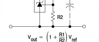
To understand the purpose of this protective device, let's find out what it consists of. So, the voltage control relay, hereinafter referred to as RKN, consists of a single housing, inside of which there is an electronic voltage controller and load disconnectors.
The controller can be made of a comparator or an electronic circuit with a microprocessor. The second option is considered more reliable, plus it allows the device to switch off smoothly.
note
As for load disconnectors, this is a conventional block of mechanical contacts operating on the principle of a contactor.
There are many varieties of RKN. For ease of use, the manufacturer is trying to improve its products by equipping them with an electronic display or other devices. Let's look at the main types of devices suitable for home use.
Plug-socket system model
The simplest device, represented by the V-protector 16AN or RN-101M models, is designed to protect an individual consumer. Its appearance resembles a simple tee or adapter. The relay on the body has a plug on one side for connecting to a socket.
On the other side of the case there is a connector where you connect the plug of any electrical appliance, for example, a refrigerator. To set the ILV response thresholds, there are buttons on the body. The electronic display is used for ease of setup and also displays the mains voltage.
A microcontroller is installed inside the case, analyzing the passing voltage and controlling the operation of the electromagnetic relay.
Extension system model
The design and operation of this relay are identical to the model discussed above. The only difference is the housing design. The appearance of the relay resembles a simple power strip type extension cord. The case is equipped with several connectors for simultaneous connection of several consumers. The product is represented by models RN-101M, ZUBR P616y and V-protector 10Acy.
DIN Rail Mount Model
An ILV of this type is mounted inside the electrical panel. It can be connected to a separate line going to a group of consumers, or the whole house. The protective device is represented by the V-protector 16-80A and ZUBR D340t models.
They are distinguished by a wide range of adjustment and the presence of independent operating modes. That is, the device is capable of operating only at high or low thresholds, as well as like a regular relay. The RLV is designed for a working load of no more than 8.5 kVA.
If the consumer's power exceeds this parameter, the relay is installed together with a contactor or magnetic starter.
By what parameters are RKN selected?
The main parameter of the ILV is its response speed. An upper limit of 0.1 s and a lower threshold of 2 s is considered a good indicator. Each device has a scale on which the user sets the upper and lower limits. When buying a relay for your apartment, you need to understand one important concept: an RKN cannot replace a voltage stabilizer.
The relay operates by cutting off the voltage supply to the electrical network when unacceptable high or low parameters are reached.
After the voltage is restored to standard parameters, the RKN automatically resumes the current supply.
That is, if there are frequent surges in the electrical network at home, it is appropriate to install a relay, but when the voltage is constantly low or high, only a stabilizer should be installed here.
Recommendations for choosing a product
- Most home networks are designed for 220 volts. You should buy a relay for this voltage. If the apartment has a powerful electric stove with three-phase wiring suitable for it, you will have to install an RKN rated at 380 volts in the electrical panel.
- For protection to be effective, it is necessary to correctly select the relay power. This device indicator should be 20% greater than the total power of all consumers in the house. The easiest way to determine this is by the circuit breaker installed inside the electrical panel. If it is rated at 32 A, then the RKN must be installed at 40 A.
- Despite the fact that the RKN protects the home network from power surges, the device itself also needs protection. The relay itself is unable to protect itself from a high voltage surge in the network. Therefore, the machine we talked about above must be placed in front of the ILV. Since the power of the machine is selected 20% lower than that of the relay, when a high voltage appears, the first device will turn off the RKN. Many may have a question, why install a relay if one machine is enough? The fact is that the ILV operates faster, and also at low limits, which ensures consumer safety. The machine will work after the relay and only at high limits.
- Some manufacturers install an electronic scoreboard on the body. This will not make the device work better or worse, it will just be more convenient for the user to configure.
- As for choosing a manufacturer, it is better to consult with specialists or read reviews on forums about different models. The fact is that new brands appear on store shelves all the time, and it is not possible to recommend something specific.
And in conclusion, it must be said that the RKN will never protect household electrical appliances from lightning. You shouldn’t even count on this and it’s better to install a lightning rod.
Options for connecting RKN to a single-phase home network
There are several options for installing the ILV. Each voltage relay connection diagram has its own characteristics and is determined by technical nuances.
The RKN can be connected to the network as an independent device or together with a contactor. The main one is the phase wire L, through which switching is carried out. Zero N is only needed to power the electrical circuit of the relay itself.
The product body has two terminal connections L, designed to connect the input and output of the phase wire. The zero terminal N can be one or two. This is not so important, since there is still a jumper inside the case. Different options are used for ease of connection.
The diagram shows how the RKN is connected without a contactor and paired with it.
The most reliable protection is considered to be the installation of an RKN after the machine, but in front of the electric meter. This allows you to protect the relay itself and the meter from a high voltage surge.
Important
Usually all electricity meters are sealed, and without a representative of the appropriate authority you will not be able to make the connection yourself. And most often, permission for such a connection may not be given. Here, another scheme is acceptable, where after the electric meter there is an automatic machine, and behind it a relay.
Types of devices
All existing magnetic relays are divided into several varieties depending on their design features, scope of application, control signal power, type of electric current, control speed.
According to the characteristics of the relay device, they can be:
- Contact. They act on the circuit with several contacts. Their closing or opening helps ensure commutation - the power circuit is either connected or broken.
- Contactless. They affect the circuit differently. These
- devices dramatically change its characteristics.
According to the scope of use, there are signaling, protective and intended for control circuits.
Electromagnetic relay
Based on the speed of action, switching devices are divided into four types:
- Adjustable. When using them, you can set any speed.
- Slowed down. They operate no earlier than after 0.05 s.
- Fast-acting. Such relays begin to operate within a millisecond.
- Inertia-free. This type of device is active even before one millisecond has elapsed.
Depending on the power of the control signal, the relay can belong to one of three main types. Power can be:
- high if its value exceeds 10 W;
- average at a value of up to 10 W, but not less than 1 V;
- small, the value of which is measured in fractions of a watt.
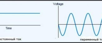
The relay can be used in AC or DC networks. The latter are polarized and neutral.
HOW RELAY WORKS [RadioamatelTV 75]
Conclusions and useful video on the topic
The video popularly explains how electromechanical switching electronics operate. The subtleties of designs, connection features and other details are clearly noted:
Electromechanical relays have been used as electronic components for quite some time. However, this type of switching devices can be considered obsolete. Mechanical devices are increasingly being replaced by more modern devices - purely electronic. One such example is solid state relays.
Have questions, found bugs, or have interesting facts on the topic that you can share with visitors to our site? Please leave your comments, ask questions, and share your experience in the contact block below the article.
Main characteristics
The magnetic device has many characteristics. Its most important parameters are the following:
- Speed of action. This is the time it takes for the device to operate after a signal is given.
- Trigger power. The minimum required to start the action.
- Controllable power. This power can be controlled by switching contacts.
- The magnitude of the operating current. This parameter is called the setpoint.
- Release current. This is the highest current value at which the sensitive plate begins to return to its starting point.
The advantage is that magnetic relay contacts have low resistance, unlike semiconductor-based switches. Another important advantage is that its metal contacts can withstand heavy network overloads. In addition, the relay can normally perform its basic functions even in the presence of static electricity. Radiation does not affect its operation.
The main advantage of the electromagnetic device is the galvanic isolation of the control and switching electrical network without secondary elements. To all of the above, it is worth adding a low price.
It also has some disadvantages. Firstly, it doesn't work very quickly. Secondly, it often fails. Thirdly, interference may occur when switching the circuit.
EVERYTHING you wanted to know about RELAYS. Types and methods of connection - in Theory and in Practice!
Installing the element into the connector
Relays are electromechanical components and are therefore subject to wear and tear. In most commercially produced devices this can be neglected - the service life of the relay is usually longer than the expected service life of the device. Even if the relay fails (for example, when welding contacts) or wears out prematurely, it is a simple and routine operation to replace the component at a service center.
The situation is different with industrial automation devices. In cases where solid state relays (SSRs) cannot be used or the device is not new, the only option left is to replace the relay regularly. Please note that devices often operate in very poor conditions, such as high humidity (causing terminal corrosion), vibration, dust (deteriorating insulation), or extremely high or extremely low temperatures. Then there is nothing left to do but use the relay socket. Some have terminals that allow both soldering into a circuit board and mounting into a socket with a clamping clamp to prevent them from falling out.
In many sockets, the contacts are located at the same distance as the relays installed in them. Thanks to this, you can add a relay socket to the device without changing the design of the printed circuit board. This is especially important when at the design stage it is not known whether a given relay will often fail. Please note that a relay built into a socket usually has a lower permissible direct contact current.
Main technical characteristics of the relay
Regardless of the principle of operation, there are generally accepted parameters that must be taken into account when choosing a device:
- Actuation time is a value that determines the time interval from the moment the control signal arrives at the input until the moment of impact on the electrical circuit;
- Switched power - the power of an electrical circuit or installation that a relay can control;
- Trigger power – the minimum value required to trigger the device;
- Setting - the magnitude of the operating current, as a rule, this is a variable indicator;
- Magnitude of current/voltage retraction/retraction - these parameters are characterized by the minimum and maximum value of the characteristics of electricity at which the armature is retracted or falls away from the contacts, that is, the electrical circuit is interrupted.
Intermediate relay RP-25 UHL4220 V and its main characteristics
Options
The main characteristics of the relay are:
- Sensitivity - switching from a signal of a certain power supplied to the winding, sufficient for switching on.
- Winding resistance.
- Actuation voltage (current) is the minimum threshold value of the parameter at which the contacts switch.
- Release voltage (current).
- Response time.
- Operating current (voltage) is the value at which guaranteed switching occurs during operation (the value is indicated within specified limits).
- Release time.
- Switching frequency with contact load.
How does an electromagnetic relay work?
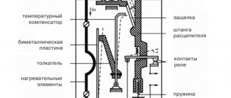
Electromagnetic relays vary depending on their purpose: executive, intermediate, communication, protection and automation devices. The most common type of this device is anchor. Such a relay is divided into 2 parts:
- Perceiving the signal. It consists of a coil on a steel core, an armature (a plate of magnetic material) and a spring.
- Executive. Consists of fixed and moving contacts.
We recommend reading: Flashlight from a cash register power supply
When no current flows to the coil, the armature is held in place by a spring. And when a signal arrives, the magnet is attracted to the core, while the moving contact comes into contact with the stationary one and the circuit is closed. If the voltage is turned off, the spring will again pull the armature to its original position and the contacts will open.
Types of contact groups
Electromagnetic relays are divided according to the method of contact operation. They can be:
- Normally closed (closed, opening). Abbreviated as NZ, on imported diagrams NC.
- Normally open (open, closing). Designation - BUT on ours - and NO on foreign ones.
- Reversible (switching). Changeover ones differ in appearance, as they have three plates with contacts. They usually only indicate common contact - they write “common” or comon.
In general, the names of the contacts make it clear how they work. Normally closed contacts are initially closed and current flows through them. When the relay is activated, the contacts open and the power circuit is interrupted.
Normally closed (closed) contact: what it means and principle of operation
Normally open (more clearly, normally open) contacts, on the contrary, are open in the normal state. When the relay is activated, the contact closes and current flows through the circuit.
Electromagnetic relay with normally open (open) contact
It’s probably already clear how a switching contact works. Unlike the first two, the switch consists of three plates. There are two fixed ones at the edges and a movable one in the center. The moving contact is often called the general contact. In the normal position, the movable plate touches one of the contacts, current flows along this path (in the figure below right).
Operating principle of an electromagnetic relay with switching contacts
When the relay is triggered, the movable contact changes position thanks to the stop frame (in the figure it is just a pin soldered to the movable plate). And the frame is attached to the anchor. After the relay is triggered, a gap appears in the first circuit, and current begins to flow in the second.
These are all types of contacts - it doesn’t seem like there are many. But all three types can be collected in one relay, and the number of groups of each type varies. They are chosen depending on need.
Main areas of application in automation systems
In most cases, EMR is used for switching loads at a switching current of 10–16 A in alternating (220 V) or direct (5–24 V) current networks. Such technical characteristics allow the relay to be used to protect such electrical installations as low-power motors, heaters, electromagnets, and other consumers with a power of up to 4 kW. In addition, relays are used to control circuits
- instrumentation and automation;
- alarm systems;
- industrial automation;
- remote control systems.
EMRs are especially effective when working with low-voltage inductive loads with a short time constant (up to 10 ms). At the same time, current overloads during startup are small, and when the equipment is turned off, voltage surges do not occur. The ability of the device to switch complex loads is ensured by its configuration with contact groups designed for the appropriate currents.
First time check
After installing a new device or a repaired EMR (after rewinding its coils), it is necessary to check the equipment. The full range of work includes the following operations.
- External inspection, internal diagnostics and maintenance (cleaning, integrity of seals, condition of seals, leads).
- Checking the contact group and mechanism. If defects are detected, they are adjusted.
- Testing of EMR for compliance of actual technical characteristics with nominal parameters when the relay is activated, returned, held.
- Checking the electrical strength of insulation.
- Checking the delay time when triggering or returning.
- Testing the system under reduced voltage conditions.
Connection features: typical diagrams
The most common scheme is to connect a single-phase load through relay contacts or a magnetic starter to protect drive mechanisms from voltage fluctuations that occur during emergency situations. Its use allows the possibility of adjusting the operating parameters of the system in a fairly wide range. For example, you can set the optimal turn-on delay.
In the diagram shown in the figure, the 220 V relay is connected directly to the controlled network. This allows the device to measure the input voltage and determine its compliance with acceptable parameters. If the value falls within the specified range, automatic reclosure is activated (automatic restart). With a set time interval, the contacts are closed and connected to the network.
The connection of a single-phase load can be carried out according to a scheme that provides for the control of switching operations through magnetic starters. The main difference in its operation is the fact that initially the MP is turned on/off, which in turn connects or disconnects the load. The device is selected in accordance with the characteristics of the connected equipment.
When using an intermediate electromagnetic relay in a circuit, its configuration depends on the nature of the connected loads. In most cases, the device functions as a contactor, which effectively distributes power between load elements.
In this case, the neutral is connected directly to the coil contact. The supply phase wire is connected through the “Stop” button, which is triggered by opening. Its second contact also joins the system phase. Normally closed contacts are used to connect the load, and normally open contacts of the intermediate EMR are used for the phase.
To ensure continuous power supply to the coil, one of the output contacts is connected to the load. The contact group is closed. To disconnect the load and EMR, the electrical circuit is broken using the “Stop” button. A magnetic starter can be additionally included in the circuit to control a high-power load. To control the relay, a thermostat, light sensors, and motion sensors can be used.
Operation of EMR, frequent equipment malfunctions
A relay is a device with a limited mechanical life: during its operation it periodically burns out, the contacts wear out, and carbon deposits form on their surface. That is why cleaning is required during routine maintenance of the EMR. In addition, it is worth considering that equipment of any type is designed for a certain number of operations. This is due to the fact that under the influence of sparks and the electric arc that is formed during switching, gradual destruction of the metal occurs.
The most common problems that arise during the operation of a relay are a break in the coil wire or the occurrence of an interturn short circuit in it. Signs of such a malfunction may be a loud hum of the EMR or failure when turned on. Externally, local overheating and interturn short circuits may be indicated by darkening on the coil. A cracking sound from the relay may indicate contact wear.
When the circuit is turned off, the EMR may remain in the active state, in which case the contacts “stick” occurs. To check the technical condition of the coil, use a multimeter or a continuity tester. If the circuit is closed, there is no break. When voltage is applied to the winding, the contact group should operate, and the circuit resistance should be zero. As part of scheduled maintenance, equipment is cleaned from dust and dirt.
Advantages and disadvantages
The electromagnetic relay has the following advantages over semiconductor competitors:
- switching large loads with small dimensions;
- galvanic isolation between the control circuit and the switching group;
- low heat generation on contacts and coil;
- small price.
The device also has disadvantages:
- slow response;
- relatively small resource;
- radio interference when switching contacts;
- the complexity of DC switching of high-voltage and inductive loads.
The operating voltage and current of the coil should not exceed the specified limits. At low values, contact becomes unreliable, and at high values, the winding overheats, the mechanical load on the parts increases, and insulation breakdown may occur.
The durability of the relay depends on the type of load and current, frequency and number of switchings. Contacts wear out the most when they open, forming an arc.
Non-contact devices have the advantage that they do not produce an arc. But there are also a lot of other shortcomings that make it impossible to replace the relay.
So, let's start with the most difficult one. What to do if the engine nameplate data is not known?
For this case, we recommend current clamps or a C266 multimeter, the design of which also includes current clamps. Using these devices, you need to determine the current of the motor in operation by measuring it in the phases.
In the case when the data on the table is partially readable, we place a table with passport data of asynchronous motors widely used in the national economy (AIR type). With its help it is possible to determine In.
Choosing the right thermal relay is one of the most important conditions for protecting an electric motor from overload. “Protection of the electric motor against overload should be installed in cases where it is possible to overload the mechanism for technological reasons, as well as under severe starting conditions and to limit the start duration at reduced voltage. Protection must be time-delayed and can be achieved by thermal relays.” (from the Installation and Start-up Instructions for Electric Motors)
First, let's look at the nameplate on the engine.
We read what the rated current of the motor is when connected to a 380 volt network (In). This current, as we see on the motor nameplate, In = 1.94 Amperes
The expression “magnitude” is a conditional term denoting how much current the selected magnetic starter can pass through the main operating contacts. When assigning a value, it is assumed that the starter operates at a voltage of 380 V, and its operating mode is AC-3.
Here is a list of differences between devices according to their values (currents depending on values):
- 0 – 6.3 A;
- 1 – 10 A;
- 2 – 25 A;
- 3 – 40 A;
- 4 – 63 A;
- 5 – 100 A;
- 6 – 160 A;
- 7 – 250 A.
The values of their permissible currents flowing through the contacts of the main circuit differ from those that I gave according to the following principles:
- category of use (it can be AC-1 -, AC3, AC-4 and 8 more categories);
- the first implies a purely resistive load (or with a small presence of inductance);
- the second is for controlling motors with slip rings;
- third – operation in the direct start mode of engines with a squirrel-cage rotor and connection thereof;
- the fourth is the start of motors with a squirrel-cage rotor, de-energizing engines that rotate slowly or are stationary, braking using the countercurrent method.
If you increase the number of the category of use, then the maximum contact current of the main circuit (if the switching wear resistance parameters are identical) will decrease.
Let's return to our sheep.
The Thermal Relay has a scale calibrated in amperes. Typically the scale corresponds to the value of the setting current (non-operation current of the relay). The relay operates within 5-20% of the excess of the set current by the consumed current of the electric motor. That is, when the electric motor is overloaded by 5-20% (1.05*In - 1.2*In), the thermal relay will operate in accordance with its current-time characteristic. Therefore, we select a relay in such a way that the thermal relay failure current is 5-10% higher than the rated current of the protected electric motor (see table below).
Major relay manufacturers
Aleph International - more than 30 years in the market of electronics, electrical goods and automation equipment. The product is considered one of the most reliable.
Axicom is a division of the Swiss company Alcatel Switzerland Ltd. Since 1999, it has been part of the Tyco Electronics concern. Produces extremely high quality products. All relay devices offered on the Russian market fully meet the requirements of domestic standards for electrical reliability and dielectric strength;
CIT RELAY & SWITCH (Zhejiang, China) - the company specializes in relay devices used in telecommunications, automotive and security. It has a wide range of products, the main advantage is the affordable price of the products;
Finder is a European manufacturer specializing in the production of relays and timers. It ranks 3rd in Europe in the production of electromechanical relay machines for industrial and domestic use. All products are certified to ISO 9001 and ISO 14001 standards.
We recommend reading: About the use of the NE555 timer and its analogues
NAiS products under this brand are manufactured by Matsushita Electric Works (Japan). Products are certified according to ISO 9001:2000 standards. The product range includes electromechanical and PhotoMOS relays, various controllers and microswitches for both industrial and domestic use.
TABLE FOR SELECTION OF THERMAL RELAYS
| Electric motor power kW | Relay RTL (for PML) | Current adjustment A | Relay RT (for PMK) | Current adjustment A |
| 0,37 | RTL-1005 | 0,6…1 | RT 1305 | 0,6…1 |
| 0,55 | RTL-1006 | 0,95…1,6 | RT 1306 | 1…1,6 |
| 0,75 | RTL-1007 | 1,5…2,6 | RT 1307 | 1,6…2,5 |
| 1,5 | RTL-1008 | 2,4…4 | RT 1308 | 2,5…4 |
| 2,2 | RTL-1010 | 3,8…6 | RT 1310 | 4…6 |
| 3 | RTL-1012 | 5,5…8 | RT 1312 | 5,5…8 |
| 4 | RTL-1014 | 7…10 | RT 1314 | 7…10 |
| 5,5 | RTL-1016 | 9,5…14 | RT 1316 | 9…13 |
| 7,5 | RTL-1021 | 13…19 | RT 1321 | 12…18 |
| 11 | RTL-1022 | 18…25 | RT 1322 | 17…25 |
| 15 | RTL-2053 | 23…32 | RT 2353 | 23…32 |
| 18,5 | RTL-2055 | 30…41 | RT 2355 | 28…36 |
| 22 | RTL-2057 | 38…52 | RT 3357 | 37…50 |
| 25 | RTL-2059 | 47…64 | ||
| 30 | RTL-2061 | 54…74 |
For most electric motors made in China, we suggest selecting the thermal relay failure current equal to the rated one. Having selected a thermal relay and the corresponding magnetic starter, we configure the thermal relay to the operating current we need.
If the motor is three-phase, then we multiply the operating current by 1.25-1.5 - this will be the setting of the thermal relay.
Operating principle of undervoltage protection
Regardless of the scope of application of ZMN, its principle of operation remains unchanged. Let us explain the protection operation algorithm using the example of an arbitrary object, where several electric motors are used for the production process and auxiliary equipment is connected. Let’s say a short circuit occurs on the line supplying the facility, causing the input switch to trip (current protection). After repair work is completed and power is restored, the following actions occur:
- Automatic start of engines, which leads to high starting currents and, accordingly, to a decrease in network voltage.
- Protection relay contacts disconnect non-critical mechanisms, that is, equipment that does not take part in the production process or whose downtime is not critical for the technological cycle. This leads to normalization of the current and increase in voltage to the nominal level, which allows for regular autostart of the main components.
EMR adjustment
The measurement method may differ significantly depending on the type of relay. When making adjustments, it is important to consider the following principles.
- Weakening the return spring leads to an increase in return time and a decrease in response voltage.
- If you increase the initial gap between the core and the armature, the operating speed will increase and the voltage will be higher. The same effect is observed when adjusting the end gap in relation to the return speed and voltage.
- With an increase in the number of make/break contacts and a simultaneous increase in spring pressure, the voltage and speed of return and operation increase, respectively.
It must be taken into account that any changes directly affect the operation of the contact system. Therefore, when adjusting the parameters of the EMR, it is necessary to select a position in which the return spring will be maximally tensioned, and the gap can provide the greatest armature stroke.
Briefly about the purpose
As is known, when the supply voltage of asynchronous motors decreases, the level of magnetic flux decreases, and, consequently, the torque. At the same time, current consumption increases, leading to a decrease in the voltage level in the electrical network, which affects the operation of other devices connected to it.
In addition, we should not forget about the starting currents generated when starting engines. ZMN shuts down less important equipment to ensure the process of self-starting of critical engines when the power grid parameters are restored. If the autostart of critical electric motors does not meet safety standards or is not expected by the technical process conditions, then a minimum voltage relay is installed on this equipment.
When the network parameters do not correspond to the minimum voltage, the ZMN shuts down the equipment and/or sends a corresponding signal to the control system or operator; this can occur in the following cases:
- In case of phase or phase-to-phase short circuit. In this case, a sharp excess of the rated current occurs, which provokes a voltage drop below the permissible level. If the current relays are triggered, the voltage will completely disappear.
- Significant excess of rated power, which also leads to a drop in voltage in the supply circuits.
The protection turns off power to equipment that is not classified as critical. This allows for normal autostart of critical electrical machines at high starting currents, otherwise false operation of relay protections may occur.
Coil supply voltage
On the relay body it is written, for example, 12 V, which means that it will require 12 V to operate. But the voltage is rarely exactly the required value. And what should you do if the voltage in the circuit drops to 9 V or rises to 15 V?
If the voltage is too high, the solenoid coil, usually sealed in a small plastic housing, will simply overheat. Joule's law is inexorable here. Fortunately, manufacturers provide some voltage reserve. Conversely, if the voltage is too low, less current will flow through the constant resistance coil, making the armature less weak in pulling. And if the current is too low, the armature will not budge at all.
The term "coil supply voltage" is imprecise because every relay manufacturer must provide at least two different coil voltages. The first is the actuation voltage, and the second is the release voltage. The switching voltage is close to the voltage indicated on the housing.
This is the value at which the manufacturer guarantees contact closure. It is given for a strictly defined temperature, most often room temperature or similar. At higher temperatures, the resistance of the wire increases, so applying the same voltage to the coil will cause a lower current to flow (which may not be enough to move the armature).
The cut-off (release) voltage informs to what value the coil supply voltage must be reduced in order for the contacts to return to their original position. Often this is only 10% of the rated voltage! Thus, a relay with a supply voltage of 5 V, indicated on the case, will turn off when the voltage drop drops to 0.5 V, which is even less than the forward voltage of the silicon pn junctions. The difference in percentage is caused by magnetic hysteresis of the ferromagnetic material from which the electromagnet core is made.
This is very convenient because it can significantly reduce the power consumption of the coil in steady state. A relay with a nominal supply voltage of 12 V is sufficient to supply voltage above 8.4 V and then decrease it (for example to 2 V). The energy savings important for battery-powered circuits will be enormous.
The actual coil supply voltage may differ from that indicated on the case, and within a fairly wide range. This is worth remembering. By tightening the armature with an electromagnet, you can reduce the supply voltage to the coil and save energy.
Types of electromagnetic relays
The first classification is based on nutrition. There are electromagnetic relays for direct and alternating current. DC relays can be neutral or polarized. Neutral ones are triggered when power is applied to any polarity, polarized ones react only to positive or negative (depending on the direction of the current).
Types of electromagnetic relays by type of supply voltage and appearance of one of the models
According to electrical parameters
Electromagnetic relays are also divided according to sensitivity:
- Trigger power 0.01 W or less - highly sensitive.
- The power consumed by the winding when triggered is from 0.01 W to 0.05 W - sensitive.
- The rest are normal.
First of all, you need to decide on the electrical parameters
The first two groups (highly sensitive and sensitive) can be controlled from microcircuits. They are quite capable of delivering the required voltage level, so that intermediate amplification is not required.
According to the level of switched load there is the following division:
- No more than 120 W AC and 60 W DC - low current.
- 500 W AC and 150 W DC - increased power;
- More than 500 W AC - contactors. Used in power circuits.
There is also a division based on response time. If the contacts close no more than 50 ms (milliseconds) after power is applied to the coil, it is fast acting. If it takes from 50 ms to 150 ms, this is a normal speed, and all those that require more than 150 ms for contacts to operate are slow.
By execution
There are also electromagnetic relays with varying degrees of tightness.
- Open electromagnetic relays. These are the ones with all the parts “in sight”.
- Sealed. They are sealed or welded into a metal or plastic case, inside of which there is air or an inert gas. There is no access to the contacts and coil; only the terminals for supplying power and connecting circuits are accessible.
- Covered. There is a cover, but it is not soldered, but is connected to the body using latches. Sometimes there is a wire loop that holds the lid in place.
The differences in weight and size can be very significant.
And another principle of division is by size. There are microminiature ones - they weigh less than 6 grams, miniature ones - from 6 to 16 grams, small-sized ones weigh from 16 grams to 40 grams, and the rest are normal.
Recommended reading: Logic analyzer
Classification
Relays are classified as follows:
- According to the method of controlling contacts - anchor and reed switches. In the first case, the contacts close and open when the armature moves. In reed switches there is no core and the magnetic field acts directly on ferromagnetic electrodes with contacts.
- The control current can be constant or variable. In the latter case, the armature and core are made of electrical steel plates to reduce losses. For direct current, devices are neutral and polarized.
- According to the response speed of the relays, they are divided into 3 groups: up to 50 ms, up to 150 ms and more than 1 s.
- Protection from external influences includes sealed, covered and open devices.
With all the variety of types presented below, the operation of an electromagnetic relay is based on the general principle of switching contacts.
The electromagnetic relay device is hidden inside the housing; only the winding and contact leads protrude from the outside. They are mostly numbered, and a connection diagram is provided for each model.
Appearance of an electromagnetic relay
The fact is that the principle of an electromagnet is used in a very important electrical product: an electromagnetic relay.
Let's take a simple electromagnetic relay
Let's see what is written on it:
TDM ELECTRIC is apparently the manufacturer. REC 78/3 - name of the relay. Next comes the most interesting part. We see some stripes and numbers. Contacts 1 to 9 are the relay switching contacts, 10 and 11 are the relay coil.
Now let's talk about everything in order. The relay consists of switching contacts. What does the phrase “switching contacts” mean? These are the contacts that perform the switching. A coil is a copper wire wound around a cylindrical piece of iron. As a result, the solenoid turns into an electromagnet if voltage is applied to its ends.
A little lower we see inscriptions such as 5A/230 V~ and 5A 24 V=. These are the maximum parameters that the relay contacts can switch. It is advisable not to exceed these parameters and take them with a large margin. Otherwise, if the permissible parameters are exceeded, the relay contacts may burn out or burn out completely, which in turn will lead to complete failure of the electromagnetic relay.
Switching time
It is clear that relays operate slower than semiconductor devices. In some devices it is necessary to enter the appropriate switching sequences. The same passive volume controls. Switching resistors quickly in the resistor divider is necessary to achieve a smooth feel when the audio volume changes quickly. The thing to remember here is that leaving the circuit open even for a moment, when one relay has already switched off and the next one has not yet activated, can lead to a very unpleasant crackling sound from the speakers. This is unacceptable in high-end audio equipment, and in a recording studio it is generally nonsense.
The time it takes for the next relay to turn on before the previous one stops working should be taken into account. And take into account the possible deviation of the supply voltage towards a decrease, as well as increased ambient temperature, which increases the switching time. Therefore, it is better to assume that the time is twice as long as indicated in the datasheets on the relay.
Electromagnetic current relays
Current and voltage relays are different, although their structure is similar. The difference lies in the design of the coil. The current relay has a small number of turns on the coil, the resistance of which is low. In this case, the winding is done with a thick wire.
The winding of the voltage relay is formed by a large number of turns. It is usually included in the existing network. Each device controls its own specific parameter with automatic switching on or off of the consumer.
Using a current relay, the current strength in the load to which the winding is connected is controlled. Information is transferred to another circuit by connecting a resistance to it with a switching contact. The connection is made to the power circuit directly or through instrument transformers.
Protective devices are fast and have a response time of several tens of milliseconds.
Typical design of EMR contacts
In addition to the classic normally open (NO) and normally closed (NC) contacts, the mechanics of relay switching also involves classification based on action.
Features of the design of connecting elements
Electromagnetic type relay designs in this embodiment allow for one or more separate switch contacts.
This is what a device looks like, technologically configured for SPST design - single-pole and unidirectional. There are also other versions available
The design of the contacts is characterized by the following set of abbreviations:
- SPST (Single Pole Single Throw) - single-pole unidirectional;
- SPDT (Single Pole Double Throw) - single-pole bidirectional;
- DPST (Double Pole Single Throw) – bipolar unidirectional;
- DPDT (Double Pole Double Throw) – bipolar bidirectional.
Each such connecting element is designated as a “pole”. Any of them can be connected or reset, simultaneously activating the relay coil.
Subtleties of using devices
Despite the simplicity of the design of electromagnetic switches, there are some subtleties in the practice of using these devices.
Thus, experts categorically do not recommend connecting all relay contacts in parallel in order to switch a high-current load circuit in this way.
For example, connect a 10 A load by connecting two contacts in parallel, each of which is rated for a current of 5 A.
These installation subtleties are due to the fact that the contacts of mechanical relays never close or open at the same time.
As a result, one of the contacts will be overloaded in any case. And even taking into account a short-term overload, premature failure of the device in such a connection is inevitable.
Incorrect operation, as well as connecting the relay outside the established installation rules, usually ends with this outcome. Almost all the contents inside were burned out
Electromagnetic products can be used as part of electrical or electronic circuits with low power consumption as switches of relatively high currents and voltages.
However, it is strictly not recommended to pass different load voltages through adjacent contacts of the same device.
For example, switch between 220V AC and 24V DC. Separate products should always be used for each option to ensure safety.
Reverse voltage protection techniques
A significant part of any electromechanical relay is the coil. This part is classified as a high inductance load because it is wire wound.
Any wire-wound coil has some impedance, consisting of inductance L and resistance R, thus forming a series circuit LR.
As current flows through the coil, an external magnetic field is created. When the current flow in the coil is stopped in the "off" mode, the magnetic flux increases (transformation theory) and a high reverse EMF (electromotive force) voltage is generated.
This induced reverse voltage value can be several times greater than the switching voltage.
Accordingly, there is a risk of damage to any semiconductor components located near the relay. For example, a bipolar or field effect transistor used to apply voltage to a relay coil.
Circuit options that provide protection for semiconductor control elements - bipolar and field-effect transistors, microcircuits, microcontrollers
One way to prevent damage to a transistor or any switching semiconductor device, including microcontrollers, is to connect a reverse biased diode to the relay coil circuit.
When the current flowing through the coil immediately after switching off generates an induced back EMF, this reverse voltage opens the reverse biased diode.
Through the semiconductor, the accumulated energy is dissipated, which prevents damage to the control semiconductor - transistor, thyristor, microcontroller.
The semiconductor often included in the coil circuit is also called:
- flywheel diode;
- shunt diode;
- reversed diode.
However, there is not much difference between the elements. They all perform one function. In addition to the use of reverse bias diodes, other devices are used to protect semiconductor components.
The same chains of RC dampers, metal-oxide varistors (MOVs), zener diodes.
Marking of electromagnetic relay devices
Technical designations that carry partial information about the devices are usually indicated directly on the chassis of the electromagnetic switching device.
This designation looks like an abbreviation and a number set.
Each electromechanical switching device is traditionally labeled. Approximately the following set of symbols and numbers is applied to the body or chassis, indicating certain parameters
Example of case marking of electromechanical relays:
RES32 RF4.500.335-01
This entry is deciphered as follows: low-current electromagnetic relay, 32 series, corresponding to the design according to the RF passport 4.500.335-01.
However, such designations are rare. More often there are abbreviated versions without explicit indication of GOST:
RES32 335-01
Also, the date of manufacture and batch number are marked on the chassis (on the body) of the device. Detailed information is contained in the technical data sheet for the product. Each device or batch is supplied with a passport.
Time relay
In automation schemes, there is often a need to create delays in the operation of devices or to issue signals for technological processes in a certain sequence. For this purpose, time delay switches are used, which have the following requirements:
- stability of exposure regardless of the influence of external factors;
- small dimensions, weight and energy consumption;
- sufficient power of the contact system.
To control electric drives, high precision requirements are not imposed. The shutter speed is 0.25-10 s. Reliability must be high, since work is often carried out in conditions of shaking and vibration. Power system protective devices must operate accurately. The shutter speed does not exceed 20 seconds. Triggering occurs quite rarely, so high demands on wear resistance are not imposed.
Electromagnetic time relays operate on the following deceleration principles:
- Pneumatic - due to the presence of a pneumatic damper.
- Electromagnetic - with direct current, there is an additional short-circuited winding in which a current is induced, preventing the increase in the main magnetic flux when triggered, as well as its decrease when switched off.
- With an anchor or clock mechanism, which is wound by an electromagnet, and the contacts are activated after counting down the time.
- Motor - supplying voltage simultaneously to the electromagnet and the motor, which rotates the cams that activate the contact system.
- Electronic - using integrated circuits or digital logic.
Drive design basics
The term "relay" is characteristic of devices that provide an electrical connection between two or more points through a control signal.
The most common and widely used type of electromagnetic relay (EMR) is the electromechanical design.
This is what one design looks like from a numerous series of products called electromagnetic relays. Shown here is a closed version of the mechanism using a transparent plexiglass cover
The fundamental control scheme for any equipment always provides the ability to turn it on and off. The easiest way to perform these steps is to use power lock switches.
Manually operated switches can be used for control, but have disadvantages. Their obvious drawback is setting the “on” or “off” states physically, that is, manually.
Manual switching devices are usually large-sized, slow-acting, capable of switching small currents.
The manual switching mechanism is a “distant relative” of electromagnetic relays. Provides the same functionality - switching working lines, but is controlled exclusively manually
Meanwhile, electromagnetic relays are mainly represented by electrically controlled switches. The devices have different shapes, dimensions and are divided according to their rated power levels. The possibilities for their application are extensive.
Such devices, equipped with one or more pairs of contacts, can be part of a single design of larger power actuators - contactors, which are used for switching mains voltage or high-voltage devices.
Electronic relay devices
Recently, analog relays have been replaced by electronic relay devices. They have significant advantages in accurately determining the source voltage, types of applied loads, power and other operating parameters. They are widely used for connecting installations with large power loads. However, their high cost and low reliability prevent them from completely replacing analog devices.
Electronic relay device control of pumping equipment
Areas of use
Electromagnetic relays are most widely used at substations for the production of electrical energy. With their help, trouble-free operation of all equipment is ensured. At the same time, relay protection is designed for switching at very high voltages - up to several hundred thousand volts.
But basically there are three areas of application for relays:
- signaling;
- protection;
- control.
Moreover, the principle of relay operation in any of the areas remains unchanged. And they are valued for their quick response to changes in the input parameters of the connected lines. Also for durability under high voltage conditions and resistance to electrical interference.
For these qualities, they participate in the reservation of power lines. Relay protection instantly disconnects damaged areas when wires are broken or shorted to ground. It should be said that a more reliable node today simply does not exist.
Not a single conveyor line in any production can do without an electromagnetic relay. Because high parasitic potentials make it practically impossible to use semiconductors. Because the latter suffer from static voltage.
Conveyor belt at the airport Source upload.wikimedia.org
Electromagnetic relays are involved in remote control of the load. They are required to be equipped with devices such as starters and contactors. Relay units are widely used in capacitor installations. The latter are needed by electric motors with very high power for their smooth start.
Electromagnetic relays, in addition to participating in the creation of the first telegraph, managed to once again distinguish themselves historically. They were used in the first electronic computers. Helped perform simple logical operations. Of course, they were very slow. But, oddly enough, they were far superior in reliability to the next generation of lamp-based computing complexes.
Relays using electromagnetic principles can be seen at every step and in everyday life. It is found in refrigerators, washing machines and other types of household appliances.
Installation features
As a rule, the thermal relay is installed together with a magnetic starter, which switches and starts the electric drive. However, there are also devices that can be installed as a separate device side by side on a mounting panel or DIN rail, such as TRN and PTT. It all depends on the availability of the required denomination in the nearest store, warehouse or garage in “strategic reserves”.
The relays are equipped with two groups of contacts, a normally closed and a normally open group, which are labeled on the body 96-95, 97-98. The picture below shows a block diagram of the designation according to GOST:
Let's consider the diagram from the article in which a three-phase motor rotates in one direction and the switching control is carried out from one place with two STOP and START buttons.
The machine is turned on and voltage is supplied to the upper terminals of the starter. After pressing the START button, the starter coil A1 and A2 is connected to the network L2 and L3. This circuit uses a starter with a 380-volt coil; look for a connection option with a single-phase 220-volt coil in our separate article (link above).
The coil turns on the starter and additional contacts No(13) and No(14) are closed, now you can release START, the contactor will remain on. This scheme is called “self-retaining start”. Now, in order to disconnect the engine from the network, you need to de-energize the coil. Having traced the current path according to the diagram, we see that this can happen when STOP is pressed or the contacts of the thermal relay are opened (highlighted by a red rectangle).
That is, if an emergency situation arises and the heater operates, it will break the circuit circuit and remove the starter from self-retaining, de-energizing the engine from the mains. When this current control device is triggered, before restarting it is necessary to inspect the mechanism to determine the cause of the shutdown, and not turn it on until it is eliminated. Often the cause of operation is high external ambient temperature; this point must be taken into account when operating the mechanisms and setting them up.
The scope of application of thermal relays in the household is not limited only to homemade machines and other mechanisms. It would be correct to use them in a heating system pump current control system. The specificity of the operation of the circulation pump is that limescale deposits form on the blades and scroll, which can cause the motor to jam and fail. Using the above connection diagrams, you can assemble a pump control and protection unit. It is enough to set the required rating of the heater in the power circuit and connect the contacts.
In addition, it will be interesting to see a diagram for connecting a thermal relay through current transformers for powerful motors, such as a pump for a water irrigation system for holiday villages or farms. When installing transformers in the power circuit, the transformation ratio is taken into account, for example, 60/5 is when the current through the primary winding is 60 amperes, on the secondary winding it will be equal to 5A. The use of such a scheme allows you to save on components without losing performance characteristics.
As you can see, the current transformers are highlighted in red, which are connected to the control relay and ammeter for visual clarity of the processes taking place. The transformers are connected in a star circuit, with one common point. Such a scheme does not pose any great difficulties in implementation, so you can assemble it yourself and connect it to the network.
Finally, we recommend watching a video that clearly shows the process of connecting a thermal relay to a magnetic starter to protect the electric motor:
That's all you need to know about connecting a thermal relay with your own hands. As you can see, installation is not particularly difficult, the main thing is to correctly draw up a diagram for connecting all the elements in the circuit!
It will be interesting to read:
- What are the differences between a contactor and a magnetic starter
- What is relay protection
- How to assemble a three-phase shield