Hello, dear readers of the site. In the previous article, we looked at the schematic diagrams for switching on a magnetic starter, which ensures reverse rotation of the electric motor.
We continue to get acquainted with the magnetic starter and today we will look at typical connection diagrams RTI- type electrothermal relay
, which is designed to protect the motor windings from overheating during current overloads.
Thermal relay: connection diagram, operating principle, purpose
Thermal relays are electrical devices whose main purpose is to protect the motor from excess load and, as a consequence, overload of the system as a whole. Today, the most common types of thermal relays are: TRN, RTI, RTT and RTL. The need to use thermal relays is due to the fact that the durability of any equipment directly depends on how often it is overloaded. Thus, when the rated voltage is regularly exceeded, the equipment heats up, which leads to aging of the insulation and, as a result, reduces the operating life of the installations.
- Thermal relay connection diagram
- Operating principle of a thermal relay
- Types of thermal relays (RTT, RTL, TRN, RTI)
Features of a thermal relay
But, unlike an automatic protective switch, the TR does not open the power supply circuits, but breaks the self-retaining circuit of the magnetic starter. The normally closed contact of the protective device acts similarly to the Stop button and is connected in series with it.
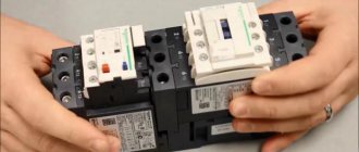
Tandem contactor and thermal relay
Since the thermal relay is connected immediately after the magnetic starter, there is no need to duplicate the functions of the contactor in case of emergency opening of the circuits. With this choice of protection implementation, significant savings in material for contact power groups are achieved - it is much easier to switch a small current in one control circuit than to break three contacts under a large current load.
The thermal relay does not directly break the power circuits, but only issues a control signal if the load is exceeded - this feature should be remembered when connecting the device.
As a rule, a thermal relay has two contacts - normally closed and normally open. When the device is triggered, these contacts simultaneously change their state.
Normally open and normally closed contacts
Characteristics of thermal relay
The choice of TP should be made by comparing the typical characteristics of this protective device according to the existing load and operating conditions of the electric motor:
- Rated protection current;
- Adjustment limit for the operating current setting;
- Power circuit voltage;
- Number and type of auxiliary control contacts;
- Switching power of control contacts;
- Operation threshold (ratio to rated current)
- Sensitivity to phase asymmetry;
- Trip class;
Connection diagram
In most schemes, when connecting a thermal relay to a magnetic starter, a normally closed contact is used, which is connected in series with the “Stop” button of the control panel. The designation of this contact is a combination of the letters NC (normal connected) or NC (normally closed).
Connection diagram of the TP to the contactor in the magnetic starter
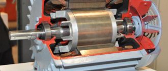
Design of a reversible magnetic motor
The distribution of these modifications is becoming more widespread every year, as they help control an asynchronous motor at a distance. This device allows you to both turn the motor on and off.
The reversing starter housing consists of the following parts:
- Contactor.
- Thermal micro relay.
- Casing.
- Management tools.
After the “Start” command has been received, the circuit is closed. Next, the current begins to be transmitted to the coil. At the same time, a mechanical blocking device operates, which prevents unnecessary contacts from starting. It should be noted here that the mechanical lock also closes the contacts of the key, this makes it possible not to keep it pressed constantly, but to calmly release it. Another important part is that the second key of this device, together with the start of the entire device, will open the electrical circuit. Thanks to this, even pressure produces virtually no result, creating additional safety.
Features of the model's functioning
Pressing the Forward key activates the coil and makes contacts. At the same time, the operation of the start key is performed by constantly open contacts of the KM 1.3 device, due to which, when the key is directly released, the power to the coil acts bypass.
After introducing the first starter, it is the KM 1.2 contacts that open, which turns off the K2 coil. As a result, when you directly press the “Back” key, nothing happens. In order to turn the motor in the opposite direction, you need to press “Stop” and turn off the power to K1. All blocking contacts can return to the opposite state, after which it is possible to drive the motor in the opposite direction. In the same way, K2 is introduced and the block with contacts is turned off. Coil 2 of starter K1 is turned on. K2 contains power contacts KM2, and K1 - KM1. A five-core wire should be connected to the buttons for connection from the starter.
Connection rules
In any installation that requires starting an electric motor in the forward and opposite directions, there is certainly an electromagnetic device with a reversible circuit. Connecting such an element is not considered as difficult a task as it might seem at first glance. In addition, the need for such tasks arises quite often. For example, in drilling machines, cutting structures or elevators, if this does not apply to home use.
The fundamental difference between a three-phase circuit and a single one is the presence of an additional control circuit and a slightly modified power part. In addition, to implement switching, such an installation is equipped with a key. Such a system is usually protected from short circuits. To do this, in front of the coils themselves in the circuit, the presence of two normally closed power contacts (KM1.2 and KM2.2), placed in positions (KM1 and KM2), is provided.
Features of connecting a thermal relay
A thermal relay is located between the magnetic starter and the electric motor. Its connection is made to the output of the magnetic starter. Electric current passes through this device. The thermal relay is characterized by the presence of additional contacts. They must be connected in series with the starter coil.
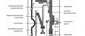
A thermal relay is characterized by the presence of special heaters through which an electric current of a certain magnitude can pass. If dangerous situations arise (current increases above the specified limits), due to the presence of bimetallic contacts, the circuit is broken and the starter is subsequently turned off. In order to start the mechanism, you need to turn on the bimetallic contacts using the button.
Connecting an electromagnetic starter and a thermal relay is quite simple. To do this, you just need to follow the scheme.
What is important to know?
To avoid repetition and to avoid piling up unnecessary text, I will briefly outline the meaning. The current relay is a mandatory attribute of the electric drive control system. This device responds to the current that passes through it to the engine. It does not protect the electric motor from short circuits, but only protects against operation with increased current that occurs during overload or abnormal operation of the mechanism (for example, wedge, jamming, rubbing and other unforeseen moments).
When choosing a thermal relay, they are guided by the passport data of the electric motor, which can be taken from the plate on its body, as in the photo below:
As can be seen on the tag, the rated current of the electric motor is 13.6 / 7.8 Amperes, for voltages of 220 and 380 Volts. According to the operating rules, the thermal relay must be selected 10-20% more than the nominal parameter. The correct choice of this criterion determines the ability of the heater to operate on time and prevent damage to the electric drive. When calculating the installation current for the 7.8 A rating given on the label, we got a result of 9.4 Amperes for the current setting of the device.
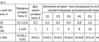
When choosing a product in the catalog, you need to take into account that this value was not the extreme value on the setpoint adjustment scale, so it is advisable to select a value closer to the center of the adjustable parameters. For example, as on the RTI-1314 relay:
How to connect a thermal relay
between the magnetic starter and the asynchronous electric motor , which is selected for the operating current of each specific motor. The thermal relay protects the motor from breakdown and operation in emergency mode, for example, the loss of one of the three phases.
The thermal relay is connected to the output from the magnetic starter to the electric motor, the current in it passes in series through the thermal relay heaters, and then to the electric motor.
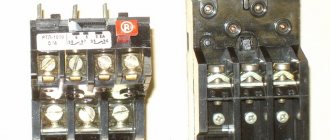
On the top of the thermal relay there are additional contacts that are connected in series to the starter coil.
Principle of operation. Thermal relay heaters are designed for a certain maximum value of current passing through them. In dangerous situations for the electric motor, when the electric current in one or more phases rises above safe limits, the heaters act on the bimetallic contacts, which break the coil control circuit, thereby turning off the starter. To turn it on again, you will need to turn on the bimetallic contacts with the button.
Keep in mind that on top of the thermal relay there is an operating current regulator within small limits. If it often knocks out after installation, I recommend increasing the current value with the regulator.
- Connecting an electric motor 380 to 220.
- How to connect a reversible magnetic .
- Operation of the magnetic starter and its
- Video 30 about connecting an electric motor.
Summary
Diagrams that depict the principle of connecting a relay to a contactor may have other letter or digital designations. Most often, their decoding is given below, but the principle always remains the same. You can practice a little by assembling the entire circuit with a consumer in the form of a light bulb or a small motor. Using the test key, you can work out a non-standard situation. The start and stop keys will allow you to check the functionality of the entire circuit. In this case, it is necessary to take into account the type of starter and the normal state of its contacts. If there are any doubts, then it is better to consult an electrician who has experience in assembling such circuits.
Checking the functionality of the circuit
In order to understand whether the circuit is assembled correctly or not, it is better not to connect the load to the starter, leaving its lower power terminals free. This way you will protect your switched equipment from unnecessary problems. We turn on the circuit breaker that supplies voltage to the object under test.
It goes without saying that it must be turned off while editing is in progress. And also, in any available way, accidental activation by unauthorized persons is prevented. If after applying voltage the starter does not turn on on its own, that’s good.
Press the “Start” button, the starter should turn on. If not, check the closed position of the “Stop” button contacts and the state of the thermal relay.
When diagnosing a malfunction, a single-pole voltage indicator helps, which can easily check the passage of a phase through the “Stop” button to the “Start” button. If, when you release the “Start” button, the starter does not lock and falls away, the block contacts are incorrectly connected.
Start and stop buttons
When starting and stopping the engine using a starter, it is convenient to connect a device with buttons connected in series with the device.
To ensure that the engine does not stop working after pressing the “start” button, self-retaining is introduced into the circuit due to the terminals paralleled with the “start”. Thanks to them, the engine runs after the “start” button is no longer pressed, until the stop button is pressed.
Voltage is supplied to the motor through any contact marked with the letter L, and it is removed from the corresponding contact under the letter T. This connection diagram is valid for a single-phase network.
vote
Article rating