Author
: elremont from 01/26/2014 Was it one of those days when the cat chewed your module? Or maybe you have an old amplifier with that nasty toxic goo leaking out of the capacitors? If you have ever been in this situation, then you could repair the module by replacing the capacitors. Let's look at an example where I replace this capacitor on a PCB. First, a little theory. What is a capacitor? A capacitor is an energy storage device that can be used to smooth out voltage. Each capacitor has two important parameters: capacitance and voltage. Capacitance tells us how much energy a capacitor can store at a given voltage. Capacitance is usually measured in microfarads (uF). In ninety-nine percent of cases, when replacing a capacitor, you need to use the same capacitance value or very close. A 470uF capacitor is used here. If I want to replace it, then ideally I should get another 470uF capacitor. Another important parameter is the rated voltage. The rated voltage is the maximum voltage at which the capacitor can operate without exploding. Once again, note that the voltage written on the capacitor means that this is the maximum voltage that can be applied to the capacitor. This does not mean that the capacitor will necessarily have this voltage. For example, this is a 16 volt capacitor. This does not mean that it is charged at 16 volts, like a battery. This means that if you charge it to 5 volts, it will work just fine. If I charge it to 10 volts everything will be fine. If I charge it to 16 volts, it can handle that too. But if I charge it to 25 volts, it will explode. Returning to our capacitor example, I see that it is rated at 16 volts. When replacing I must use a 16V or higher capacitor. Now it turns out that all the 470 uF capacitors I have are rated 25 volts. But it's not a problem. If the original circuit calls for a 16V capacitor, then I can use a 25V capacitor, it just means I have more safety margin. Now let's talk about polarity. The negative side of an electrolytic capacitor will always have a small minus symbol on it. All you need to do is make sure the polarity matches the old capacitor. If you reverse the polarity, this is what happens. So now that I know the polarity, I'll replace the capacitor and solder it in place. Finally, a little safety warning. If you have ever seen these large capacitors at voltages greater than 200 volts, then you must be careful with them so as not to touch them if they are charged. Remember that a capacitor charged at 200V can kill you. Happy capacitor replacement! _
Starting and running capacitors are used to start and operate electric motors operating in a single-phase 220 V network.
That's why they are also called phase shifters.
Installation location: between the power line and the starting winding of the electric motor.
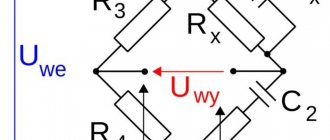
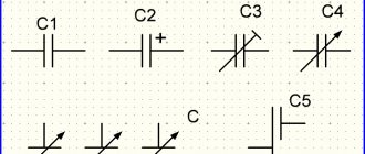
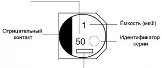
Symbol for capacitors in diagrams
The graphic designation on the diagram is shown in the figure, the letter designation is C and the serial number according to the diagram.
Basic parameters of capacitors
The capacitance of a capacitor characterizes the energy that the capacitor is capable of accumulating, as well as the current that it is capable of passing through itself. Measured in Farads with a multiplying prefix (nano, micro, etc.).
The most commonly used values for run and start capacitors range from 1 μF to 100 μF.
The rated voltage of a capacitor is the voltage at which the capacitor is able to operate reliably and for a long time, maintaining its parameters.
Well-known capacitor manufacturers indicate on its body the voltage and the corresponding guaranteed operating time in hours, for example:
- 400 V - 10,000 hours
- 450 V - 5000 hours
- 500 V - 1000 hours
How to choose a capacitor
To better understand the algorithm for the correct actions, you can study the process of selecting a capacitor when connecting an electric motor to different power sources. If a three-phase network is used, the capacitance formula is suitable:
Where:
- k – fixed coefficient equal to 2,800/4,800 for the “star”/“triangle” circuit, respectively;
- Iph – current in the stator circuit, which manufacturers indicate on the nameplate or in the accompanying documentation;
- U – supply voltage.
In a simplified version, specialists take 6-7 µF for every 0.1 kW of power consumption. Under significant mechanical loads, the winding may burn out. A soft start of the electric motor is ensured by an additional capacitor. It performs its functions within 2-5 seconds. The capacity is chosen 2.5-3.5 more than the result of the previous calculation. The rated voltage is 50-70% higher than the operating parameters of the power supply network.
An asynchronous motor is connected to a single-phase source. In this option, it is necessary to create a phase shift to start rotating the rotor. Starting is provided by a separate winding. A special capacitor is installed in this circuit. For a simplified selection circuit, take 8-12 μF for every 0.1 kW of power consumption.
For your information. To prevent overheating and damage to parts, it is recommended to connect inductive loads of this type through capacitors designed for an operating voltage of at least 450 V.
Calculation of a quenching capacitor for connecting an LED strip can be done using the formula:
Where:
- I – current in the circuit;
- Up (Ud) – power supply voltage (drop across diodes), respectively.
Checking the starting and running capacitors
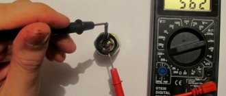
You can check the capacitor using a capacitor capacitance meter; such devices are produced both separately and as part of a multimeter, a universal device that can measure many parameters. Let's consider checking with a multimeter.
- de-energize the air conditioner
- discharge the capacitor by short-circuiting its terminals
- remove one of the terminals (any)
- We set the device to measure the capacitance of capacitors
- We lean the probes against the terminals of the capacitor
- read the capacity value from the screen
All devices have different designations for the capacitor measurement mode; the main types are shown below in the pictures.
In this multimeter, the mode is selected by a switch; it must be set to Fcx mode. The probes must be inserted into the sockets marked Cx.
Switching the capacitance measurement limit is manual. Maximum value 100 µF.
This measuring device has an automatic mode, you just need to select it, as shown in the picture.
The Mastech measuring tweezers also automatically measure capacitance, you just need to select the mode with the FUNC button, pressing it until the F indication appears.
To check the capacitance, we read its value on the capacitor body and set a deliberately larger measurement limit on the device. (If it's not automatic)
For example, the nominal value is 2.5 μF (μF), on the device we set 20 μF (μF).
After connecting the probes to the terminals of the capacitor, we wait for the readings on the screen, for example, the time to measure a capacitance of 40 μF with the first device is less than one second, with the second one more than one minute, so you should wait.
If the rating does not correspond to that indicated on the capacitor body, then it must be replaced and, if necessary, an analogue must be selected.
A little about security
It is no secret that replacing low-voltage capacitors can only be harmful to health if the polarity connection is incorrect. The first time you turn it on, the capacitor will explode. The second danger that can be expected from capacitors is the voltage between its plates. If you've ever taken apart computer power supplies, you've probably noticed the huge 200V electrolytes. It is in these capacitors that dangerous high voltages remain that can seriously injure you. Before replacing the capacitors of the power supply, we recommend completely discharging it either with a resistor or a 220V neon lamp.
Helpful advice: such capacitors do not like to be discharged through a short circuit, so do not short-circuit their terminals with a screwdriver to discharge them.
In the element base of a computer (and not only) there is one bottleneck - electrolytic capacitors. They contain an electrolyte; the electrolyte is a liquid. Therefore, heating such a capacitor leads to its failure, as the electrolyte evaporates. And heating in the system unit is a regular occurrence.
Therefore, replacing capacitors is a matter of time. More than half of the failures of motherboards in the middle and lower price categories are due to dry or swollen capacitors. Even more often, computer power supplies break down for this reason.
Since the printing on modern boards is very dense, replacing capacitors must be done very carefully. You can damage and not notice a small unframed element or break (short) tracks, the thickness and distance between which is slightly greater than the thickness of a human hair. It’s quite difficult to fix something like this later. So be careful.
So, to replace capacitors you will need a soldering iron with a thin tip with a power of 25-30 W, a piece of thick guitar string or a thick needle, soldering flux or rosin.
If you reverse the polarity when replacing an electrolytic capacitor or install a capacitor with a low voltage rating, it may well explode. And here's what it looks like:
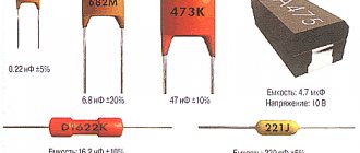
So, carefully select the replacement part and install it correctly. Electrolytic capacitors are always marked with a negative terminal (usually a vertical stripe of a different color from the body color). On the printed circuit board, the hole for the negative contact is also marked (usually with black shading or solid white). The ratings are written on the capacitor body. There are several of them: voltage, capacity, tolerances and temperature.
The first two are always present, the others may be absent. Voltage: 16V
(16 volts).
Capacitance: 220µF
(220 microfarads). These values are very important when replacing. The voltage can be chosen equal or with a higher nominal value. But the capacitance affects the charging/discharging time of the capacitor and in some cases can be important for a section of the circuit.
Therefore, the capacity should be selected equal to that indicated on the case. On the left in the photo below is a green swollen (or leaking) capacitor. In general, there are constant problems with these green capacitors. The most common candidates for replacement. On the right is a working capacitor, which we will solder.
The capacitor is soldered as follows: first find the legs of the capacitor on the back side of the board (for me this is the most difficult moment). Then heat one of the legs and lightly press the capacitor body from the side of the heated leg. When the solder melts, the capacitor tilts. Carry out a similar procedure with the second leg. Usually the capacitor is removed in two steps.
There is no need to rush, and there is no need to press too hard. The motherboard is not a double-sided PCB, but a multilayer one (imagine a wafer). Overdoing it can damage the contacts on the inner layers of the printed circuit board. So no fanaticism. By the way, long-term heating can also damage the board, for example, lead to peeling or tearing of the contact pad. Therefore, there is no need to press hard with a soldering iron either. We lean the soldering iron and press lightly on the capacitor.
After removing the damaged capacitor, it is necessary to make holes so that the new capacitor can be inserted freely or with little effort. For these purposes, I use a guitar string of the same thickness as the legs of the part being soldered. A sewing needle is also suitable for these purposes, but needles are now made of ordinary iron, and strings are made of steel. There is a chance that the needle will get caught in the solder and break when you try to pull it out. And the string is quite flexible and steel and solder adhere much worse than iron.
When removing capacitors, solder most often clogs the holes in the board. If you try to solder the capacitor in the same way that I advised you to solder it, you can damage the contact pad and the track leading to it. Not the end of the world, but a very undesirable occurrence. Therefore, if the holes are not clogged with solder, they simply need to be expanded. And if you do, then you need to press the end of the string or needle tightly to the hole, and on the other side of the board, lean the soldering iron against this hole. If this option is inconvenient, then the soldering iron tip should be leaned against the string almost at the base. When the solder melts, the string will fit into the hole. At this moment you need to rotate it so that it does not grab the solder.
After obtaining and expanding the hole, it is necessary to remove excess solder from its edges, if any, otherwise, during soldering of the capacitor, a tin cap may form, which can solder adjacent tracks in those places where the seal is dense. Pay attention to the photo below - how close the tracks are to the holes. Soldering this is very easy, but difficult to notice, since the installed capacitor interferes with the view. Therefore, it is very advisable to remove excess solder.
If you don’t have a radio market nearby, then most likely you can only find a used capacitor for replacement. Before installation, its legs should be treated, if necessary. It is advisable to remove all solder from the legs. I usually coat the legs with flux and tin them with a clean soldering iron tip, the solder collects on the soldering iron tip. Then I scrape the legs of the capacitor with a utility knife (just in case).
That's all, actually. We insert the capacitor, lubricate the legs with flux and solder. By the way, if you use pine rosin, it is better to crush it into powder and apply it to the installation site than to dip a soldering iron in a piece of rosin. Then it will work out neatly.
Design and purpose of capacitors
This element of the electrical circuit consists of two plates (plates). The plates are positioned relative to each other so that there is a gap between them. When a capacitor is connected to an electric current circuit, charges accumulate on the plates. Due to the physical gap between the plates, the device has low conductivity.
Attention! This gap can be air or filled with a dielectric. The following dielectrics are used: paper, electrolyte, oxide films.
The main feature of such a two-terminal network is the ability to accumulate electric field energy and instantly transfer it to the load (charge and discharge).
The first prototype of the container was the Leyden jar, created in 1745 in the city of Leiden by the German von Kleist. The jar was lined with copper foil inside and out. This is how the idea of creating covers came about.
The graphic designation of a two-terminal network on diagrams and drawings is two vertically located lines (like plates) with a gap between them.
Is it possible to install a larger capacitor?
The exact answer to the question raised in this section can be given after studying a specific diagram. If you need to select a part for a filter (oscillatory circuit), similar parameters are required. Otherwise, the frequency characteristics will not correspond to the design intent.
When smoothing out ripples in the power supply, such an upgrade instead of a standard product can be effective. In some cases, to limit the current in the circuit, you will have to select a suitable resistor. Through it it will be possible to discharge the capacitor without damage. The final decision is made taking into account the factors discussed above. Operating conditions, thermal and mechanical loads are essential. A reasonable increase in costs at the stage of purchasing reliable components will extend the service life of a functional device.
Characteristics
The voltage created on the plates of a two-terminal network is equal to the potential difference:
Knowing the voltage and charge, you can calculate the capacitance (C). This is one of the main characteristics of a two-terminal network:
Where:
- C – capacitance, F (farad);
- q – charge accumulated by a two-terminal network, C (coulomb);
- U – voltage, V.
Electrical capacity is a physical quantity that is determined by dividing the plate charge by the potential difference between the plates. The unit of measurement for C is farad (F).
For your information. A capacitance equal to 1 F is a large value, so in practice it is measured: in microfarads (μF), picofarads (pF), nanofarads (nF).
Other parameters of the two-terminal network include:
- energy density;
- Rated voltage;
- polarity.
Abbreviations
The standard version includes permanent (K) and trimmer (CT) capacitors. Variables (CV) are created according to individual orders. Below are individual parameters according to GOST 13 453-68.
Dielectric material:
- B – paper;
- MP – metal/film combination;
- C – mica;
- E – electrolyte;
- K – ceramics.
According to the degree of protection from external influences, a hermetic (G) version and a pressurized housing (O) are distinguished.
Design:
- M – monolith;
- B – barrel;
- D – disk;
- C – sectional option.
Operating mode (current):
- I – pulse;
- U – universal (pulse, constant and variable);
- H – only constant;
- P – variable/constant.
Other features:
- U – capacitor designed to operate in the VHF range;
- M – compact dimensions;
- T – preservation of technical parameters is ensured when the temperature rises;
- B – the product is suitable for installation in high voltage networks.
The standard designation indicates (by position number):
- type of capacitor (K, CT or KP);
- code for dielectric and basic parameters (K10 ceramics for voltage up to 1600 V);
- current operating mode;
- production series or other technological designation.
Additional information:
- You can select products by combined (numeric and alphabetic) color marking;
- Abbreviations are applied to the compact body (instead of 1000uF - 1000m);
- The accuracy class is indicated in Latin font (U is ±);
- The rated voltage (Q-160V) is encoded in the same way.
Simple ways to connect an electric motor
The simplest way to turn on motors is to connect to a three-phase network. The electrical windings of the motor are connected in two ways:
The connection order is indicated on the terminal cover on the reverse side.
Attention! Connecting the windings in a delta quickly brings the motor to maximum power, but then the starting current increases sevenfold. A soft start, in the absence of a starting rheostat, is difficult.
The star connection of the windings allows the motor to operate steadily and for a long time with a smooth start. The machine can withstand short-term overloads and does not overheat. Its power is slightly lower than with an alternative connection.
The beginnings of the windings can be connected to one point during manufacturing. Only three of their ends are brought out to the terminal block. Therefore, the conclusions are simply connected to the network phases. The direction of rotation is selected by reversing the connection of the terminals to two adjacent phases.
Abbreviations
The standard version includes permanent (K) and trimmer (CT) capacitors. Variables (CV) are created according to individual orders. Below are individual parameters according to GOST 13 453-68.
Dielectric material:
- B – paper;
- MP – metal/film combination;
- C – mica;
- E – electrolyte;
- K – ceramics.
According to the degree of protection from external influences, a hermetic (G) version and a pressurized housing (O) are distinguished.
Design:
- M – monolith;
- B – barrel;
- D – disk;
- C – sectional option.
Operating mode (current):
- I – pulse;
- U – universal (pulse, constant and variable);
- H – only constant;
- P – variable/constant.
Other features:
- U – capacitor designed to operate in the VHF range;
- M – compact dimensions;
- T – preservation of technical parameters is ensured when the temperature rises;
- B – the product is suitable for installation in high voltage networks.
The standard designation indicates (by position number):
- type of capacitor (K, CT or KP);
- code for dielectric and basic parameters (K10 ceramics for voltage up to 1600 V);
- current operating mode;
- production series or other technological designation.
Additional information:
- You can select products by combined (numeric and alphabetic) color marking;
- Abbreviations are applied to the compact body (instead of 1000uF - 1000m);
- The accuracy class is indicated in Latin font (U is ±);
- The rated voltage (Q-160V) is encoded in the same way.
Specifics of circuits with capacitors
When selecting the types of switching on of electric machines using starting and working two-terminal circuits for a 220 volt network, the following are distinguished:
- inclusion in the “triangle”;
- star connection.
For your information. What are the differences between starting and working two-terminal networks? “Starting” are elements that are used only for starting, and “working” are those that are constantly used in operation.
Connection diagrams for a 380 V line
There is no need to use capacitive elements when connecting a 3-phase motor to a 380 volt network.
Schemes for connecting to a single-phase network
When installing a single-phase motor in a single-phase line, it is started using an additional winding. Such a motor has three outputs:
- from the working coil;
- from additional;
- common output for both windings.
When there is no marking, the coils are “ringed” by a tester to determine the correct connection.
Assembly type "Triangle"
To connect an asynchronous three-phase machine to a single-phase line, it is possible to use a delta connection. The starting capacitance is turned on according to the diagram.
Assembly type "Star"
The principle of assembling the starting circuit of a 3-phase motor, the windings of which are connected by a star, is similar. When it is possible to independently make such a connection of the windings, it is carried out on the terminal block.
Connection diagrams
The circuit that has a starting capacitor in the network has become more widespread.
This scheme has certain nuances:
- The starting winding and capacitor are turned on when the engine starts.
- The additional winding operates for a short time.
- The thermal relay is included in the circuit to protect the additional winding from overheating.
If it is necessary to provide high torque during startup, a starting capacitor is included in the circuit, which is connected together with the working capacitor. It is worth noting that quite often its capacity is determined empirically to achieve the highest starting torque. Moreover, according to the measurements taken, the value of its capacity should be 2-3 times greater.
The main points of creating an electric motor power circuit include the following:
- From the current source, 1 branch goes to the working capacitor. It works all the time, which is why it got its name.
- In front of it there is a branch that goes to the switch. In addition to the switch, another element can be used that starts the engine.
- A starting capacitor is installed after the switch. It operates for a few seconds until the rotor picks up speed.
- Both capacitors go to the motor.
In a similar way, you can connect a single-phase electric motor.
Capacity size: working and starting
The specific capacity of these elements can be calculated using an online calculator on the Internet. The calculation is done independently using formulas.
For the trigger element
There are two known formulas for determining the capacity of a starting two-terminal network:
- for the “star” circuit – Cп = 2800*I/U;
- for the “triangle” circuit – Cп = 4800*I/U.
The rated current is calculated using the expression:
Here:
- P – motor power;
- U – network voltage;
- η – efficiency;
- cosϕ – power factor.
For work item
You can select a working capacitor based on the following calculation:
A running and stable engine requires the use of a working tank to rotate under load.
Divisions of capacitors with the possibility of changing the capacitance
According to this parameter, parts in this category are divided into:
Specific names determine the main design features and intended purpose. A typical permanent capacitor is created from conductive plates, rolled into a roll to reduce size. A dielectric is installed between them. The assembly is placed in a metal case or filled with polymer to provide the necessary security parameters.
In variable and tuning models, sets of mechanically driven plates are used. By changing the position of the working elements, the required capacity value is established. Each product is designed for a specific range of operating parameters. Such capacitors are used to fine-tune the oscillatory circuit. They are installed in radio-electronic units to regulate individual operating parameters during operation.
Which type to use
The requirements for capacitors for starting electric motors are simple:
- the capacity is sufficient to start the engine;
- the rated voltage is selected 10-15% higher than the connected one;
- The two-terminal network must work with the applied type of current.
There are small nuances for electric machines that differ in operating principles.
For operation with a three-phase electric motor
In this case, the part carries out a phase shift in the winding of an asynchronous machine, and its capacitance must be high. Creation of a starting torque and further operation under load require a more precise selection of this element characteristic.
Switching on with a single-phase electric motor
Starting capacitors are used here to connect an additional winding. It is designed to start the motor and can be turned on either permanently, through a two-terminal network, or briefly without it.
Part selection features
The selected starting capacitors correspond to the applied voltage. The size of their capacity should not allow the engine to overheat during operation and should be easy to start when turned on. There are no particular difficulties with the selection of elements.
Model overview
There are several popular models that can be found on sale.
It is worth noting that these models differ not in capacity, but in type of design:
- Metallized polypropylene versions of the SVV-60 brand. The cost of this version is about 300 rubles.
- NTS film brands are somewhat cheaper. With the same capacity, the cost is about 200 rubles.
- E92 – products of domestic manufacturers. Their cost is small - about 120-150 rubles for the same capacity.
There are other models, often differing in the type of dielectric used and the type of insulating material.
A capacitor is a passive electronic component that has two poles with a fixed or variable capacitance value. It also has low conductivity
It is important to understand what a capacitor is for in an electric motor and car, because according to the information provided on the forums, many people have the wrong idea about this and simply underestimate the importance of this device
What is a capacitor used for?
The device is used in all electrical and radio circuits. For what purposes is a capacitor included in the circuit:
- Acts as a resistance, which allows it to be used as a filter to suppress high-frequency and low-frequency interference.
- They are used for photo flashes and lasers, and all thanks to the device’s ability to accumulate charge and quickly discharge, creating a pulse.
- Helps compensate for reactive energy, allowing it to be used in industry.
- Thanks to the ability to accumulate and retain charge for a long time, a capacitor can be used to store information and power low-power devices.
What is a car capacitor used for?
This device can perform several functions in the car. For example, they are used to create high voltage levels throughout the entire electrical system in a car. Most often, a capacitor is used for car acoustics. Speaking about why condensates are needed in car audio, we note that its main purpose is to help the amplifier quickly deliver the available power at low frequency peaks.
If a capacitor is not used in the speaker system, then the bass sound will not be as clear, and there may also be a drawdown in the power supply to the entire electrical network of the car. Such power surges can ultimately lead to the subwoofer simply breaking down.
When choosing a capacitor for a car, follow the rule that there should be 1 F per 1 kW of power. Choose high-quality capacitors and it is best if they have charge control capabilities.
It's also worth figuring out how to properly install the capacitor. It is best to do this as close as possible to the subwoofer amplifier, since this is where the heaviest load is placed. The distance should not be more than 60 cm. Connection type – parallel.
Why is a capacitor needed in an electric motor?
For some motors to operate properly, it is necessary to use a starting and running capacitor. The main purpose of the starting capacitor is to improve the starting performance of the engine. This device helps reduce the time it takes for the engine to enter its operating mode, while increasing torque and facilitating the engine starting process.
As for the working capacitor, it is involved in work throughout the entire operating time of the engine. This device ensures the heating of the windings permissible by standards, optimal load capacity and efficiency of the electric motor. It also contributes to maximum torque and increased engine life.
Now you need to find out which capacitor is needed for the motor. The capacitance of this device is usually selected on the basis that there should be 6.6 mF per 100 W. Sometimes this value is incorrect, so it is best to select the capacity through experimentation. There are several selection methods, but the most accurate values can be obtained by connecting the motor via an ammeter
It is important to control the current consumption at different capacities. The task is to find at what capacitance the current value on the ammeter will be minimal
Using Electrolytic Capacitors
To start operation of a three-phase motor from 220V, the starting capacitor must have a large capacity. To move the shaft of an engine with a power of 3 kilowatts, 2100 uF of capacitance is needed. To select such a value of C, you will need a whole battery of non-polar components. Electrolytic two-terminal networks (electrolytes) have a larger capacity with smaller dimensions. But their inclusion in the alternating current circuit for a long time is unacceptable.
Carefully. When the container is connected for a long time, the electrolyte boils and the element explodes.
Table of capacitor analogues
Write in the comments what analogues of foreign or domestic capacitors you know and we will add them to the table.
Correct selection of a capacitor ensures the operation of the electrical circuit in strict accordance with the technical specifications. For some structures, in addition to the container, it is necessary to ensure certain dimensions and resistance to adverse external influences. This publication will help you find suitable products in the assortment of specialized stores.
Connecting an electric motor with your own hands
How to choose a capacitor for a single-phase motor is already clear. The selection of capacitors for a three-phase motor is considered. How to practically mount a circuit to start an engine, what is necessary for this?
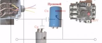
The circuit consists of the following components:
- engine (up to 3 kW);
- capacitors: starting and running, which differ in capacity;
- 220 V PVS start button.
Why do you need a start button? For short-term connection of an electrolytic two-terminal network and starting the motor rotation. The circuit is assembled according to the diagram in the picture below. All connections are made using bolted clamps. Bare sections of wires are subject to mandatory insulation.
The use of starting and operating capacitors makes it possible to start motors in any circuit. The capacity of the two-terminal circuits should be sufficient to start rotation and stable operation under load. It is preferable to use new parts.
Divisions of capacitors with the possibility of changing the capacitance
According to this parameter, parts in this category are divided into:
Specific names determine the main design features and intended purpose. A typical permanent capacitor is created from conductive plates, rolled into a roll to reduce size. A dielectric is installed between them. The assembly is placed in a metal case or filled with polymer to provide the necessary security parameters.
In variable and tuning models, sets of mechanically driven plates are used. By changing the position of the working elements, the required capacity value is established. Each product is designed for a specific range of operating parameters. Such capacitors are used to fine-tune the oscillatory circuit. They are installed in radio-electronic units to regulate individual operating parameters during operation.
Announcements on NN.RU - Construction
Milan kitchen table new with free delivery to your doorstep in the city of Nizhny Novgorod Dzerzhinsk. Size: 1154*752*756 mm frame: legs. Price: 4,500 rub.
OPGS in bags and in bulk! Seven days a week! Delivery throughout the city and region! Any form of payment! Price: 1,350 rub.
Set of kitchen corner table stools new free delivery within the city of Nizhny Novgorod Dastorg factory offers - kitchen corners with. Price: 8,050 rub.
I will deliver a new ash orchid set for free around the city of Nizhny Novgorod, Dzerzhinsk. There are other colors and models from RUB 5,000 on sale. Price: 7,500 rub.
There is a real construction boom in Nizhny Novgorod. In every district of the city, new houses are appearing that will be rented out in the coming years.
How to choose a capacitor
To better understand the algorithm for the correct actions, you can study the process of selecting a capacitor when connecting an electric motor to different power sources. If a three-phase network is used, the capacitance formula is suitable:
Where:
- k – fixed coefficient equal to 2,800/4,800 for the “star”/“triangle” circuit, respectively;
- Iph – current in the stator circuit, which manufacturers indicate on the nameplate or in the accompanying documentation;
- U – supply voltage.
In a simplified version, specialists take 6-7 µF for every 0.1 kW of power consumption. Under significant mechanical loads, the winding may burn out. A soft start of the electric motor is ensured by an additional capacitor. It performs its functions within 2-5 seconds. The capacity is chosen 2.5-3.5 more than the result of the previous calculation. The rated voltage is 50-70% higher than the operating parameters of the power supply network.
An asynchronous motor is connected to a single-phase source. In this option, it is necessary to create a phase shift to start rotating the rotor. Starting is provided by a separate winding. A special capacitor is installed in this circuit. For a simplified selection circuit, take 8-12 μF for every 0.1 kW of power consumption.
For your information. To prevent overheating and damage to parts, it is recommended to connect inductive loads of this type through capacitors designed for an operating voltage of at least 450 V.
Calculation of a quenching capacitor for connecting an LED strip can be done using the formula:
Where:
- I – current in the circuit;
- Up (Ud) – power supply voltage (drop across diodes), respectively.
Selecting equipment for replacing a capacitor
Of course, you should not choose a soldering iron that is only suitable for tinning buckets and pans. Finding such a necessary tool will not be difficult. Fortunately, now is not the time of total shortage and it is very easy to find any tool. As well as capacitors that should be used to replace those installed on the motherboard.
Why replace capacitors on the motherboard when the computer already works. That is, it is in good condition. There seems to be no reason to interfere and fix something that is already in good working order. But ask yourself whether your computer is running smoothly. Compare with how it worked when you just bought it?
You may not pay attention, but the computer crashes from time to time, freezes, or suddenly reboots. And one of the reasons for failures or so-called “glitches” are capacitors, which lose their capacity over time. Electrolytic condensates have such a property that they “dry out” over time.
Replacing the capacitor is a simple repair
The rated capacity of capacitors decreases by at least ten percent per year even during storage. Being involved in electrical circuits, capacitors lose their capacity even more quickly due to specific operating conditions and inevitable heating.
Replacing the capacitor is a simple repair
About capacitors
The property of loss of initial capacity is often not taken into account. Although when calculating a computer, as a rule, a certain reserve of capacity is taken into account. However, computer assembly is carried out in China. They solder capacitors into the circuits that do not have the appropriate capacity, but smaller ones, or, in order to save money, do not install some of the capacitors at all. This is easily detected by the free holes; looking at any motherboard or other board in the light, it is easy to see a “sieve” of unfilled seats.
Capacitors are installed on the motherboard in order to filter noise in the power supply circuits. Although they use surge protectors and uninterruptible power supplies, they cannot cope with all the interference from the electrical network.
When mains voltage fluctuations occur, even within the permissible range of values, these fluctuations reach the processor itself. And he, in turn, is very picky about the supply voltage. Even hundredths of a volt matter for the processor core, you can verify this by looking at the computer settings.
Recharging the capacitors smoothes out the rectified voltage that supplies the power circuits of the central processor, RAM, chipsets and other peripherals. The stability of the computer depends on how smooth the supply voltage is.
Therefore, it makes sense to replace all filter capacitors after a year or a couple of years of computer operation. This will not only prolong the operation of the computer, but also ensure its uninterrupted operation, i.e. will “rejuvenate” the computer.
Is it possible to install a larger capacitor?
The exact answer to the question raised in this section can be given after studying a specific diagram. If you need to select a part for a filter (oscillatory circuit), similar parameters are required. Otherwise, the frequency characteristics will not correspond to the design intent.
When smoothing out ripples in the power supply, such an upgrade instead of a standard product can be effective. In some cases, to limit the current in the circuit, you will have to select a suitable resistor. Through it it will be possible to discharge the capacitor without damage. The final decision is made taking into account the factors discussed above. Operating conditions, thermal and mechanical loads are essential. A reasonable increase in costs at the stage of purchasing reliable components will extend the service life of a functional device.
Capacitor in DC circuit
So, we take a constant voltage power supply and set the voltage on its crocodiles to 12 Volts. We also take a 12 Volt light bulb. Now we insert a capacitor into the open circuit.
No, the light is not on.
But if you exclude the capacitor from the circuit and connect it directly to the light bulb, then the lamp lights up.
This suggests a conclusion: direct current does not flow through the capacitor! That is, in a direct current circuit, an ideal capacitor has an infinitely large resistance.
To be honest, at the very initial moment of applying voltage, the current still flows for a few seconds. It all depends on the capacitance of the capacitor.