How to read electrical diagrams. Connecting wires and electrical communication lines
Hello, dear readers of the site. In the previous article, we looked at the three main types of electrical circuits used in radio and electrical engineering, and in continuation of the topic of how to read electrical circuits, we will begin to study the conventional graphic symbols of the elements with which electrical circuits are built. Let's start with the simplest thing - connecting wires and electrical communication lines .
If you look at the schematic diagram, you will notice the abundance of parallel and intersecting straight lines. All these lines represent connecting wires
or
electrical communication lines
that connect the parts of any electrical device.
Connection points symbolizing an electrical connection in the form of soldering, twisting, welding, etc. are depicted with a blackened dot
, and if the lines intersect without a connection, then
a dot is not placed
.
Sometimes you can still find old circuit diagrams, where, when crossing electrical communication lines, the lack of connection was indicated by a special outline
, the use of which has now been abandoned, as it complicated the drawing work. Contours were used because of the fear that the human eye might mistakenly see a point at the intersection and thereby create an erroneous idea of the connection.
For ease of reading, communication lines and connections between parts in diagrams are usually depicted horizontal
and
vertical
lines. Branches of connecting wires and lines are depicted at an angle of 90°, but in some cases it is allowed to depict branches at angles that are multiples of 45°.
The length and location of the connecting lines on the diagram in no way reflect the actual length of the wire or its location in the real device. It may happen that the longest connecting line shown in the diagram in a real device will represent a short conductor or its complete absence, because the parts are connected to each other by leads.
Or it may turn out that the shortest line in the diagram will be an image of the longest conductor in a real device. The main thing to understand here is that in the diagrams the connecting line only shows that a certain terminal of one part is electrically connected to another specific terminal of another part
.
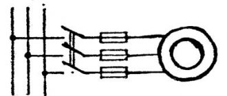
Sometimes on circuit diagrams, in order to reduce the number of connecting lines that have a common functional purpose, a single-line image is used, which represents one common connecting line
, into which single lines merge and branch in the right place. In this case, each single line at the input and output is assigned the same number, by which it is identified in the circuit. Both regular and thickened images of the common line are allowed.
As an example, consider part of the display unit circuit. The diagram shows that pin 2 of the DD2 PIC16F84 microcontroller enters the common line at number 4 (red arrow) and, leaving the common line, is connected to pin 22 of the HG1 CA58-11SR indicator. Or pin 6 of the DD2 microcontroller enters the common line at number 1 (dark arrow) and, leaving the common line, is connected to pin 7 of the DD1 K514ID2 decoder.
When assembling complex electrical devices consisting of independent blocks, the blocks are included in the overall circuit of the device using connecting wires, which are tied into bundles
, which makes installation beautiful and neat.
On circuit diagrams and wiring diagrams, the harness is depicted as a line of normal thickness, but the fact that it is a bundle is indicated by branches
single lines.
To make it easier to find in which direction the second end of a single line is located, the line is depicted with a short break
at an angle of 45°. GOST also allows for a more simplified option, although less convenient, when the wires of the harness are branched without a break.
In electrical devices, for example, audio equipment or measuring equipment, shielded conductor
. This is due to the fact that, under certain conditions, an ordinary conductor can excite an electromagnetic field in the surrounding space or, conversely, an emf can be induced in it under the influence of an external magnetic field, for example, an alternating current background.
To eliminate this effect, the wire is enclosed in a grounding metal sheath
, excluding the propagation of the magnetic field, both along the wire and from it.
Such a shell is called a screen
, and the method of protection itself is called
shielding
.
As a rule, the screen is made of thin copper wires woven in such a way that they form a kind of “jacket” or braid over the wire insulation. Shielding is carried out by connecting one end of the braid to the common power pole or to the device body.
The shielded conductor is indicated by a dashed line and is depicted on circuit diagrams either by a dashed circle
, or a regular
connecting line
, on both sides of which there are
two parallel dashed lines
, conventionally depicting the longitudinal section of the shielding shell.
When they want to show that a line is shielded all the way from one element of the circuit to another, the shielding is indicated by a dashed circle. When it is necessary to show only part of the shielded section, the shielding is shown not along the entire communication line, but in its individual sections.
The dashed lines depicting the screen are considered as a conventional representation of the elements, and therefore it is allowed to attach other connecting lines to them, showing the connection, for example, connecting the screen to the body of an electrical device.
In electrical devices operating at ultrahigh frequencies, a coaxial cable
, which has a fairly high noise immunity.
The coaxial cable has a circular cross-section and is a central
and
outer
conductors, which are covered
with an outer protective sheath
that protects the cable from mechanical damage.
Center conductor
made entirely of copper or copper-plated steel, and is located exactly along the axis of the outer conductor, which explains the name “coaxial”.
The outer conductor
is a flexible conductive
braid
(
screen
) made of copper wire or aluminum foil with copper-bonded aluminum braid.
Due to the shielding effect of the outer conductor, the electromagnetic field in a coaxial cable is concentrated in the space between the two conductors, which provides absolute protection from the influence of external electromagnetic waves and eliminates losses of the electromagnetic field. It turns out that the cable practically does not emit radio waves.
Coaxial cable is widely used in terrestrial, cable and satellite television systems, in video surveillance systems, in computer networks, in communication systems, etc.
On schematic diagrams, a coaxial cable is depicted as a solid circle with a line segment tangent to it. The solid circle emphasizes that the outer shell is impervious to electromagnetic waves.
The coaxial cable, as well as the shielding conductor, can be electrically connected to other lines indicating the connection, for example, with grounding or with a common wire.
If the electrical communication line is only partially made by cable, then the sign is modified: the tangent line to the circle is directed only in one direction. The example in the figure below shows that there is no coaxial line on the right side of the sign.
Well, that’s basically all I wanted to say about connecting wires and electrical communication lines . Good luck!
Literature:
1. GOST 2.721-74 Conventional graphic symbols in diagrams. Designations for general use.
2. Zgut M.A. Symbols and radio circuits.
3. Klyuev A.S. Techniques for reading automatic control and process control circuits.
Search for phase and neutral
The work of a professional electrician always has an increased degree of danger, and especially in cases where you have to redo or repair electrical wiring that someone else has done and manually determine what color the wire is
is responsible for the phase. Sometimes a specialist is faced with a situation where the wiring in an apartment or on a panel is made with monochrome wires or without complying with color matching requirements. Then, in order to avoid the danger of receiving an electric shock, the installer has to use his knowledge and use the appropriate tool.
To manually determine where the phase is and where the zero is
or grounding conductor, an electrician can use several tried and true techniques:
- use a hand indicator or “probe”. To do this, you need to turn off the power supply, strip a pair of de-energized conductors, removing 1-2 cm of insulation from them, separate the wires and re-apply current to the electrical circuit. Carefully taking the indicator probe-screwdriver and without touching its working part, you need to touch each core by pressing the metal part (see figure) at the base of the device handle. If the “probe” lamp lights up, then this wire is phase, and the other is neutral,
- if the apartment electrical wiring is made not of a pair, but of 3 wires, then, in addition to phase and zero, you will have to determine the “ground”, which is impossible using only a manual indicator. Having found the phase conductor with a “probe”, you should use a multimeter. The device will need to set the measurement mode to 220 V, turn it on and, taking both probes in your hands, touch one of them to the phase conductor, and the other to the first of the remaining ones. Having remembered the value shown by the device, we touch the other “X” wire and remember the result. Simultaneously touching a pair of phase-zero wires with the multimeter probes will produce the standard current voltage of your household network, i.e. 220 V, and the value of the phase-ground pair will be smaller.
By the way, you can also use a multimeter to determine which of the unrecognized conductors is a phase conductor. It is necessary to set the switch to a voltage greater than 200 V and touch the conductors with a probe inserted into the “V” socket: the phase will show 8-15 V, and the neutral will leave the device needle at zero.
There are many useful videos on the Internet that allow you to visually familiarize yourself with the color marking system for wires, as well as gain practical skills on the questions “how to understand where the phase is and where the zero is” or “how to calculate the phase, neutral and grounding in the wiring for an outlet.”
Wire colors in electrical wiring
The color identification scheme is convenient not only for installation. As a rule, different contractors install and operate electrical wiring. Compliance with standards prevents errors during repair work and in the modernization process.
Something to remember! Domestic standards have changed several times over the past decades. Currently, the markings discussed above are used.
Color of zero working and zero protective wires
The color options for the shells will help you recognize the intended purpose of the conductors:
- blue – working zero;
- transverse or longitudinal combinations of yellow and green stripes - protective zero;
- main blue with a change to a combination of yellow and green stripes at the junctions - combined working and protective zero.
For your information. The last universal option can be done in the reverse way. The main part of the line is created from a combination of yellow and green stripes, with blue color applied at the junctions.
Color of wires plus (+) and minus (-) in DC networks
Is the red wire positive or negative? Such questions arise when working with DC electrical circuits.
Red
To remember which plus is red or black, they use the name of a well-known international organization - the Red Cross. This phrase suggests that red means plus.
Black
Black color indicates the negative conductor. These markings can be seen on typical household equipment:
- power supplies;
- audio, video equipment;
- other devices with electronic software control units.
Plus
The polarity of conductors must be observed when repairing standard electrical equipment of cars. In some situations, confusion with plus and minus is accompanied by a violation of the functional state.
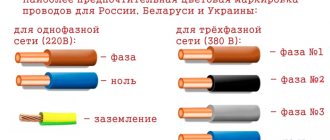
Colors for 220V and 380V networks
Installation of single- and three-phase electrical networks is facilitated if the wiring is made with multi-color wire. Previously, a flat two-core white wire was used for single-phase residential wiring. During installation and repair, to eliminate errors, it was necessary to ring each core individually.
The production of cable products with colored cores in different colors reduces the labor intensity of the work. To indicate phase and zero in single-phase wiring, it is customary to use the following colors:
- red, brown or black – phase wire;
- other colors (preferably blue) – neutral wire.
The phase markings in a three-phase network are slightly different:
- red (brown) – 1 phase;
- black – 2 phase;
- gray (white) – 3 phase;
- blue (cyan) – working zero (neutral)
- yellow-green – grounding.
Domestic cable products comply with the standard for core coloring, so a multiphase cable contains differently colored cores, where the phase is white, red and black , the neutral is blue , and the ground is yellow-green conductors.
How to determine ground, zero and phase on wires if there are no markings
It is more difficult to determine in practice than in theory. Not all manufacturers comply with the standards. Therefore, when laying a two-phase 220 V network with grounding, you have to use a VVG cable with blue, brown and red colors. Combinations may be different, but without complying with regulatory requirements.
For your information. In old wiring from “Soviet times” there is no color marking. Identical white (gray) shells do not allow the purpose and correspondence of the lines to be known by simple visual inspection.
To avoid problems, it is recommended to carry out installation work using the same type of cable products. When color coding is not available, it should be created at the joints using insulating tape or heat shrink tubing. The latter option is preferable, as it is designed to maintain integrity for a long time.
Below are methods for determining phase and neutral wires with the advantages and disadvantages of each option. In any case, first clarify the network parameters. In old houses, for example, a two-wire connection scheme with a single working and grounding conductor is often used.
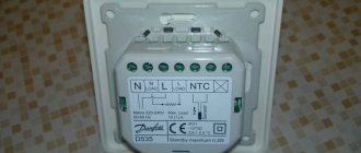
The figure shows a modern network with separate grounding and working zero connections. It is possible to connect three- and single-phase loads.
Determining the phase using an indicator screwdriver
Touching the tip of such a device to the phase wire closes the current circuit. This is accompanied by the warning lamp or LED lighting up. A built-in resistor limits the current to a safe level.
Advantages of the indicator:
- minimum cost;
- compactness;
- reliability;
- durability;
- autonomy;
- good protection from adverse external influences.
The disadvantage is the limited measurement accuracy. Under certain conditions, false positives cannot be ruled out.
Determination of ground, zero and phase using a test lamp
To reproduce this technology, you need to prepare a simple design. An incandescent lamp designed for the appropriate mains voltage is screwed into a standard socket. Connect wires of sufficient length to perform work operations in a specific location.
Next, connect one of the wires to the known zero line. Others sequentially check other cable cores. Lighting of the lamp indicates the presence of a phase.
Using a measuring device
When checking a 220 V household network, you do not need to know how to determine the polarity. The power supply is organized using alternating current, so set the multimeter switch to the appropriate position. Touching the phase-zero (phase-ground) wires with the probes is accompanied by an indication of the corresponding voltage (≈220 V). The potential difference between the neutral conductor and ground is minimal.
For your information. When checking an old two-wire circuit, one of the probes touches the reinforcement in a concrete slab, a radiator of a heating system, or another grounded element of a building structure.
When switching to constant voltage, the multimeter will show where the plus and minus are. In the absence of reliable information about the electrical parameters in the circuit, they begin with the maximum measurement range with a sequential transition to smaller values with insufficient accuracy.
Such a “device” is useful for testing DC circuits in the absence of specialized measuring instruments. Bubbles near the negative wire are the release of hydrogen during the electrolysis reaction. The area near the plus will take on a greenish tint after a few minutes.
Using LED
You can create a control device with your own hands by analogy with an indicator screwdriver. Instead of a light bulb, install AL 307 or another LED with similar characteristics. A 100-120 kOhm resistor with a power of 1-2 W is added in series to the circuit.
Letter designation of wires
Color markings can be supplemented by letters. Partially the symbols for the designation are standardized:
- L (from the word Line) – phase wire;
- N (from the word Neutral) – neutral wire;
- PE (from the combination Protective Earthing) - grounding;
- “+” – positive pole;
- “-” – negative pole;
- M – midpoint in DC circuits with bipolar power supply.
To designate the protective grounding connection terminals, a special symbol is used, which is stamped on the terminal or on the device body in the form of a sticker. The grounding symbol is the same for most countries in the world, which reduces the likelihood of confusion.
In multiphase networks, the symbols are supplemented by the serial number of the phase:
- L1 – first phase;
- L2 – second phase;
- L3 – third phase.
There is marking according to old standards, when the phases are designated by symbols and C.
A deviation from the standards is the combined phase designation system:
- La – first phase;
- Lb – second phase;
- Lc – third phase.
In complex devices, additional symbols may be found that characterize the name or number of the circuit. It is important that the markings of the conductors match throughout the entire circuit where they are involved.
Letter designations are applied with indelible, clearly visible paint on the insulation near the ends of the cores, on sections of PVC insulation or heat-shrinkable tube.
Connection terminals may have marks that indicate circuits and power polarities. Such signs are made by painting, stamping or etching, depending on the material used.
Color coding in household electrical networks
Before the introduction of the standard for multi-colored cores, their insulation was black or white, which seriously complicated installation work, especially if it was necessary to reconnect existing circuits. The problem of constantly searching for an answer to the question “ where is the phase and where is the zero?”
"was quite spicy.
According to GOST requirements, any conductor in electrical appliances and installations operating in networks up to 1 kV must have a strictly defined color. We list the main colors that are found in the marking of various types of cores:
- neutral or zero (N) – the neutral working conductor is made in blue or light blue. On the distribution panel, the zero is attached to a special bus using a terminal or a bolt under a nut, welded to the body of the box (the panel of the old design),
- protective neutral conductor (PE), “ground”, ground wire
–
the color
of this conductor is always yellow-green, designed in the form of longitudinal or transverse stripes on the insulation of the current-carrying conductors, - combined neutral wire (neutral + ground, PEN) – marked yellow-green with blue marks at the ends or vice versa,
- phase (L) – one of the colors shown in the figure. The most common phase conductors are those with red, white, black or brown insulation. The phase on the panel always comes to the “machine” or fuse.
The color marking of the working core of a single-phase electrical network, created from a branch from a 3-phase circuit, must necessarily coincide with the color of the original conductor core of the “mother” network.
The standards for color marking of electrical conductors are designed so that the colors of the insulation of the current-carrying conductors are never even remotely similar to the color of the neutral conductors. In the case of using unmarked cables, appropriate distinctive markings are made at their ends, at the points of connection, using multi-colored electrical tape, cambric or heat shrink.