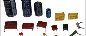
Capacitors
– electronic components consisting of two conductor plates and a dielectric located between them. There are many types of capacitors that have a similar design, but differ in the materials from which the plates and dielectric layer are made, and in their functions in electronic circuits. The type of product is determined by the shape, color, and markings on the case.
High voltage capacitors
High-voltage devices (voltage multipliers, Marx generators, Tesla coils, high-power lasers, etc.) use high-voltage capacitors that differ in design from low-voltage capacitors. They are used in circuits with voltages greater than 1600 V. Some types of high-voltage electronic devices:
- K75-25 – pulse models used in circuits with voltages up to 50 kV. Their capacitance is 2-25 nF. Due to the ability to work with currents with a frequency of 500 Hz, they are effective in Tesla spark coils.
- K15-4. This type of capacitor can be identified by its green cylindrical body. They have a small capacitance and are used in Marx generators, old televisions, voltage multipliers and other high-voltage, low-frequency circuits.
- K15-5. Ceramic parts of brick color, compact dimensions, disk shape. The maximum voltage is 6.3 kV, used in high-frequency filters.
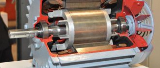
Use of electric motors in everyday life
Electric motors are present in almost all areas of our lives. Any device, be it a hair dryer, microwave or computer, contains electric motors. They are, of course, for the most part miniature, and our task is to figure out how to select the capacitor capacity for a three-phase motor with a power of 180 W to 3 kW. Such motors can be used in equipment such as an emery machine, a compressor, a circular saw, a planer, and a grain crusher. Naturally, each case requires its own type of engine; more on this below.
Ceramic capacitors
Ceramic and glass-ceramic capacitors with a solid inorganic dielectric layer are available in high-voltage and low-voltage versions. They are compact in size and reliable. Widely in demand in computing, household, medical, military equipment, and transport. Based on their rated voltage, they are divided into high- and low-voltage.
The following ceramic capacitors are produced by design type:
- KTK – tubular;
- KDK – disk;
- SMD – surface and others.
To make ceramic capacitors, they do not use baked clay, but materials similar to it in structure - ultraporcelain, tikond, ultrasteatite. The lining is a silver layer. Ceramic and glass-ceramic devices are used in circuits in which frequency characteristics, low leakage losses, compact dimensions, and low cost are important.
Tips for checking electronic components (capacitors)
Capacitor elements have one not very pleasant property. The fact is that during soldering, when the parts are exposed to heat, they often cannot be restored. However, it is possible to qualitatively examine the element only if it is removed from the circuit. Otherwise, parts located nearby will shunt it. For this reason, it is necessary to take into account certain nuances.
When the diagnosed capacitor can be soldered back into the circuit, the device being repaired will need to be put into operation. This will allow you to track its work. If performance has successfully resumed, the device has begun to function more efficiently, then the tested component is replaced with a new one.
Important information! To shorten the test, you should desolder not two, but only one of the pins. It is necessary to take into account and understand that this method cannot be used for the vast majority of electrolytic cells. This is due to the specific design features of the case itself.
If the circuit is complex and includes a significant number of capacitors, then defects are calculated by measuring the voltage across them. If the parameter does not meet the requirements, the part that causes suspicion should be removed and checked.
If faults are detected in the circuit, you need to double-check the manufacturing date of the electronic component. The element dries out within five years of operation and is more than 65%. Such a part, even if it is in working order, must be replaced. Otherwise, it will worsen the performance of the entire circuit.
Modern generation multimeters are distinguished by the fact that their highest indicator for measurement is the capacitance parameter, which varies around 200 μF. If this indicator is exceeded, the control device is capable of leaving the operating state, even if it has a fuse. New generation electrical engineering includes high-tech SMD electrical capacitors. Their difference and advantage is their very small size.
Soldering one pin from such a component is a very difficult task. Here the best solution would be to raise one of the terminals after unsoldering, then isolate it from the circuit, or completely separate the two terminals.
Paper and metal-paper capacitors
In paper capacitors, the foil plates are separated by a dielectric made of capacitor paper. These parts are used in both high frequency and low frequency circuits. They are not popular due to their low mechanical strength. A more durable option is a metal-paper part, in which a metal layer is sprayed onto the paper.
Paper and metal-paper capacitors are produced in a wide range of capacities and rated voltages. Metal-paper options benefit in terms of compact design and lose in terms of stability of insulation resistance. An additional advantage of metal and paper products is the ability to self-heal electrical strength in isolated cases of paper breakdown.
Model overview
There are several popular models that can be found on sale.
It is worth noting that these models differ not in capacity, but in type of design:
- Metallized polypropylene versions of the SVV-60 brand. The cost of this version is about 300 rubles.
- NTS film brands are somewhat cheaper. With the same capacity, the cost is about 200 rubles.
- E92 – products of domestic manufacturers. Their cost is small - about 120-150 rubles for the same capacity.
There are other models, often differing in the type of dielectric used and the type of insulating material.
Electrolytic capacitors
Electrolytic capacitors are characterized by increased energy intensity and are used in AC and DC circuits. In them, the dielectric is a metal oxide layer created by an electrochemical method. It is located on a plus cover made of the same metal. The other cover is liquid or dry electrolyte. Metal – aluminum, niobium or tantalum.
Fixed capacitors are obsolete. They were replaced by parts with variable electrical capacity. The most common electrolytic capacitors are the tuning type. Their capacitance changes when adjusted, but remains constant during operation of the circuit. Thanks to the sealed housing and solid semiconductor, the products are shelf stable and can be used at low temperatures (down to -80°C) and high frequencies.
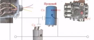
Auxiliary or starting winding in a single-phase motor
To independently start and start rotating, another coil is specially installed on a single-phase electric motor. Only thanks to it the rotor and shaft begin to move and begin to rotate.
Such a coil (starter) is installed on the stator, but is shifted relative to the working one by 90 degrees. That is, the auxiliary and main windings are perpendicular to each other. And so that not only the coils, but also the currents are shifted, an element called a phase shifter is connected to the circuit.
You can shift phases using the following devices:
- active resistor;
- capacitor;
- inductive coil.
It should be noted that a motor with a capacitor connected as a phase-shifting element will produce better performance during operation and startup.
The main parts of the engine - the stator and rotor - are made of metal. Only a certain type of metal is used for their production. This is 2212 electrical steel.
Film and metal film capacitors
Polystyrene film products are in demand in pulsed circuits, with direct or high-frequency alternating current. Such products are produced with foil coverings or with a film dielectric, on which a thin metallized layer is applied. Polycarbonate, Teflon, polypropylene, and metallized paper are used to make film dielectrics. Capacitance range – 5 pF-100 µF. High-voltage versions of film capacitors are very popular - up to 2000 V.
Various types of film capacitors are available, which differ in:
- placement of dielectric layers and plates - axial and radial;
- case materials - polymer and plastic; models without a case with epoxy coating are produced;
- shape – cylindrical and rectangular.
The main advantage of such products is their ability to self-heal, protecting them from the possibility of premature failure. Other advantages are good electrochemical characteristics, thermal stability, and the ability to withstand high loads at alternating current. Due to the properties listed above, film and metal film products are used in measuring technology, radio electronics, and computer technology.
CHIP capacitors
Also called SMD capacitors. These radio components are designed for surface mounting. Types of leadless capacitors:
Chip capacitors have compact dimensions, a standardized body shape, and characteristics that largely coincide with multilayer capacitors. They are used in printed circuit boards both individually and in sets.
A little history
Back in 1841, the English physicist Charles Winston introduced the first single-phase motor, which did not yet know how to spin on its own. This was done manually or using another engine.
In 1884-1885, a motor was developed that had armature windings and field windings and was called “universal”. This was done by Hungarian engineers, co-authors of the transformer Miksha Deri and Otto Blati, and independently of them Werner Siemens. Electric motors of this type are still used today.
In addition, Nikola Tesla was involved in the development of electric motors. The first capacitor motor was developed by French engineers Maurice Hitin and Maurice Leblanc in 1890. How to choose a capacitor for a three-phase motor in our time, we will understand further.
Table of capacitor analogues
Write in the comments what analogues of foreign or domestic capacitors you know and we will add them to the table.
Correct selection of a capacitor ensures the operation of the electrical circuit in strict accordance with the technical specifications. For some structures, in addition to the container, it is necessary to ensure certain dimensions and resistance to adverse external influences. This publication will help you find suitable products in the assortment of specialized stores.
Divisions of capacitors with the possibility of changing the capacitance
According to this parameter, parts in this category are divided into:
Specific names determine the main design features and intended purpose. A typical permanent capacitor is created from conductive plates, rolled into a roll to reduce size. A dielectric is installed between them. The assembly is placed in a metal case or filled with polymer to provide the necessary security parameters.
In variable and tuning models, sets of mechanically driven plates are used. By changing the position of the working elements, the required capacity value is established. Each product is designed for a specific range of operating parameters. Such capacitors are used to fine-tune the oscillatory circuit. They are installed in radio-electronic units to regulate individual operating parameters during operation.
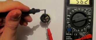
Checking capacitors without desoldering them from the board
You can do without removing capacitors from the board to test them. The main condition is that the board itself is completely de-energized. After a power outage, you will need to wait a certain amount of time for the electrical components to discharge.
You should know that to get 100% results, it will be impossible to do without desoldering the element from the board. Parts that are located nearby interfere with reliable verification. You only need to make sure that there is no breakdown.
To check the proper functioning of the capacitor, without desoldering, it is necessary to touch the terminals of the element with probes to measure the resistance. Based on the type of capacitor, the diagnosis of the parameter itself will differ.
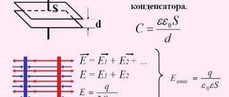
Properties and parameters of capacitors
The main parameter of devices in this category is capacity (C). It determines the storage properties of the product. The operating principle is based on the transfer of electrons to the corresponding plate when a power source is connected. Depending on the polarity, positive (negative) charges appear on the corresponding electrode.
The size of the capacity depends on several parameters:
- plate sizes (plating area);
- distances between them;
- dielectric properties of the material in the gap.
For your information. Capacity is indicated in multiple units. Example: pF or pF is picofarad (10-12 farads).
The voltage of a flat capacitor is calculated using the formula:
Where:
- q – charge;
- e – dielectric constant;
- S – working area.
From this expression it is easy to conclude about the mutual influence of electrical and structural parameters. Capacity is determined as follows:
Where:
- d – distance between plates;
- U – voltage.
For convenience, a specific indicator is used:
where V is the volume of the product.
Based on it, a conclusion is drawn about how effectively the capacitor performs its main functions. With a high specific capacity, discharging takes longer if a similar load is connected.
The accuracy class or percentage deviation indicates the tolerance from the nominal capacity (values are indicated ± in%):
Consumer parameters of a dielectric are characterized by electrical strength. As a rule, the voltage rating in long-term operating mode for certain conditions is indicated on the product body, taking into account the ranges:
- temperature;
- relative humidity;
- pressure.
Detailed documentation indicates the breakdown voltage.
Inductance (self) changes the field strength of the capacitor. This reactive component “helps” the product discharge faster or slower compared to the design speed of the process. Such parasitic influences distort the operating characteristics of the oscillatory circuit. They must be taken into account when designing frequency-dependent circuits.
Losses are estimated by the electrical resistance of the insulating layers. If you connect the multimeter accordingly, you can clarify the actual leakage current. This parameter is measured over a certain period of time. It should be remembered that resistance depends on temperature and humidity.
For your information. Mica capacitors will discharge more slowly than paper capacitors under equal conditions, since the leakage currents differ by an order of magnitude.
For a comprehensive comparison of different parts in this category, stability is checked. This indicator characterizes the constancy of operating parameters. As a rule, the influence of temperature is taken into account. The specialized coefficient (TKE) shows the corresponding changes with an increase (decrease) of 1°C.
How to discharge a capacitor to minimize residual voltage? The answer to this question will help to obtain the study of absorption processes in the dielectric layer. The corresponding parameters are characterized by a correction factor (Ka). It increases with increasing temperature.
What is a three-phase motor?
In the distribution box, the contacts are usually shifted - opposite C1 is not C4, but C6, opposite C2 - C4.
When a three-phase motor is connected to a three-phase network, a current begins to flow through its windings at different times in turn, creating a rotating magnetic field that interacts with the rotor, causing it to rotate. When the motor is turned on in a single-phase network, no torque is created that can move the rotor.
Among the different ways to connect three-phase electric motors to a single-phase network, the simplest is to connect the third contact through a phase-shifting capacitor.
Not all three-phase electric motors are capable of working well in single-phase networks, but most of them cope with this task quite satisfactorily - except for the loss of power. Basically, for operation in single-phase networks, asynchronous motors with a squirrel-cage rotor (A, AO2, AOL, APN, etc.) are used.
Designation on plate A
indicates that the motor windings can be connected either as a “triangle” (at 220V) or as a “star” (at 380V). When connecting a three-phase motor to a single-phase network, it is advisable to use a delta circuit, since in this case the motor will lose less power than when connected to a star.
If the operating voltage of the engine is 220/127V, then the engine can only be connected to a single-phase 220V network using a star circuit. If you connect 220V in a delta circuit, the engine will burn out.
Beginnings and ends of windings (various options)
Perhaps the main difficulty in connecting a three-phase motor to a single-phase network is to understand the wires going into the junction box or, in the absence of one, simply leading out of the motor.
The simplest case is when in an existing 380/220V motor the windings are already connected in a delta circuit. In this case, you just need to connect the current supply wires and the working and starting capacitors to the motor terminals according to the connection diagram.
If the windings in the motor are connected by a “star”, and it is possible to change it to a “triangle”, then this case also cannot be classified as complex. You just need to change the connection diagram of the windings to a “triangle”, using jumpers for this.
The second task (determining the beginning and end of the windings) is somewhat more complicated and requires a battery and a pointer voltmeter. Digital is not suitable due to inertia. The procedure for determining the ends and beginnings of the windings is shown in diagrams 1 and 2.
Schemes for connecting a three-phase motor to a single-phase network
It is convenient to start a three-phase motor using a special switch, one pair of contacts of which closes when the button is pressed. When it is released, some contacts open, while others remain on - until the “stop” button is pressed.
Reverse
. The direction of rotation of the motor depends on which contact (“phase”) the third phase winding is connected to.
Abbreviations
The standard version includes permanent (K) and trimmer (CT) capacitors. Variables (CV) are created according to individual orders. Below are individual parameters according to GOST 13 453-68.
Dielectric material:
- B – paper;
- MP – metal/film combination;
- C – mica;
- E – electrolyte;
- K – ceramics.
According to the degree of protection from external influences, a hermetic (G) version and a pressurized housing (O) are distinguished.
Design:
- M – monolith;
- B – barrel;
- D – disk;
- C – sectional option.
Operating mode (current):
- I – pulse;
- U – universal (pulse, constant and variable);
- H – only constant;
- P – variable/constant.
Other features:
- U – capacitor designed to operate in the VHF range;
- M – compact dimensions;
- T – preservation of technical parameters is ensured when the temperature rises;
- B – the product is suitable for installation in high voltage networks.
The standard designation indicates (by position number):
- type of capacitor (K, CT or KP);
- code for dielectric and basic parameters (K10 ceramics for voltage up to 1600 V);
- current operating mode;
- production series or other technological designation.
Additional information:
- You can select products by combined (numeric and alphabetic) color marking;
- Abbreviations are applied to the compact body (instead of 1000uF - 1000m);
- The accuracy class is indicated in Latin font (U is ±);
- The rated voltage (Q-160V) is encoded in the same way.
Determining voltage using a multimeter
It is possible to check the proper operation of the capacitor by measuring the voltage, then comparing the result obtained with the nominal value. To perform diagnostics, you need a power source whose voltage should be slightly less than that of the element being tested.
For example, if the capacitor has a value of 25 V, then a 9-volt source will do. Connect the probes to the legs, first paying attention to the polarity, then wait a little time - about a few seconds. It happens that time has passed, and the expired component is still functioning, although the characteristics are different. In such a case, it needs to be systematically monitored.
How to choose a capacitor
To better understand the algorithm for the correct actions, you can study the process of selecting a capacitor when connecting an electric motor to different power sources. If a three-phase network is used, the capacitance formula is suitable:
Where:
- k – fixed coefficient equal to 2,800/4,800 for the “star”/“triangle” circuit, respectively;
- Iph – current in the stator circuit, which manufacturers indicate on the nameplate or in the accompanying documentation;
- U – supply voltage.
In a simplified version, specialists take 6-7 µF for every 0.1 kW of power consumption. Under significant mechanical loads, the winding may burn out. A soft start of the electric motor is ensured by an additional capacitor. It performs its functions within 2-5 seconds. The capacity is chosen 2.5-3.5 more than the result of the previous calculation. The rated voltage is 50-70% higher than the operating parameters of the power supply network.
An asynchronous motor is connected to a single-phase source. In this option, it is necessary to create a phase shift to start rotating the rotor. Starting is provided by a separate winding. A special capacitor is installed in this circuit. For a simplified selection circuit, take 8-12 μF for every 0.1 kW of power consumption.
For your information. To prevent overheating and damage to parts, it is recommended to connect inductive loads of this type through capacitors designed for an operating voltage of at least 450 V.
Calculation of a quenching capacitor for connecting an LED strip can be done using the formula:
Where:
- I – current in the circuit;
- Up (Ud) – power supply voltage (drop across diodes), respectively.
Concept of an asynchronous motor
An asynchronous motor designed for 220 V requires power from alternating current. Such a motor must be connected to a single-phase network. A 220 V single-phase asynchronous motor will work properly if the mains voltage is also 220 V and the frequency is 50 Hz.
Such meanings can be found in any living conditions throughout the former Soviet Union. But in the United States, for example, the household voltage is 110 V.
As for production, in countries that were formerly part of the USSR, you can find single-phase and three-phase and several other types of electrical networks.
Is it possible to install a larger capacitor?
The exact answer to the question raised in this section can be given after studying a specific diagram. If you need to select a part for a filter (oscillatory circuit), similar parameters are required. Otherwise, the frequency characteristics will not correspond to the design intent.
When smoothing out ripples in the power supply, such an upgrade instead of a standard product can be effective. In some cases, to limit the current in the circuit, you will have to select a suitable resistor. Through it it will be possible to discharge the capacitor without damage. The final decision is made taking into account the factors discussed above. Operating conditions, thermal and mechanical loads are essential. A reasonable increase in costs at the stage of purchasing reliable components will extend the service life of a functional device.
Current power through resistor
Let alternating current flow through a resistor with a resistance of . The voltage across the resistor, as we know, oscillates in phase with the current:
Therefore, for instantaneous power we obtain:
(2)
The graph of power (2) versus time is shown in Fig. 1. We see that the power is non-negative all the time - the resistor takes energy from the circuit, but does not return it back to the circuit.
Rice. 1. AC power through resistor
The maximum value of our power is related to the amplitudes of current and voltage by the usual formulas:
In practice, however, what is of interest is not the maximum, but the average
current power. This is understandable. Take, for example, an ordinary light bulb that is lit in your home. A current with a frequency of Hz flows through it, i.e., fluctuations in current and voltage occur per second. It is clear that over a sufficiently long time, a certain average power is released from the light bulb, the value of which is somewhere between and . Where exactly?
Look again carefully at Fig. 1. Don’t you have an intuitive feeling that the average power corresponds to the “middle” of our sinusoid and therefore takes on the value ?
This feeling is absolutely true! The way it is. Of course, we can give a mathematically strict definition of the average value of a function (in the form of some integral) and confirm our guess with direct calculation, but we don’t need this. An intuitive understanding of a simple and important fact is enough:
the average value of the square of the sine (or cosine) over the period is equal to
.
This fact is illustrated in Figure 2.
Rice. 2. The average value of the squared sine is
So, for the average value of the current power across the resistor we have:
(3)
In connection with these formulas, the so-called active
(or
effective
) values of voltage and current (in fact, these are nothing more than the
root mean square
values of voltage and current. We have already encountered this: the root mean square speed of the molecules of an ideal gas (sheet “Equation of State of an Ideal Gas”):
(4)
Formulas (3), written in terms of effective values, are completely similar to the corresponding formulas for direct current:
Therefore, if you take a light bulb, connect it first to a constant voltage source, and then to an alternating voltage source with the same effective value, then in both cases the light bulb will burn equally brightly.
The effective values (4) are extremely important for practice. It turns out that AC voltmeters and ammeters show exactly the effective values
(that's how they are designed).
Know also that the notorious volts from the outlet are the effective
value of the household power supply voltage.
Divisions of capacitors with the possibility of changing the capacitance
According to this parameter, parts in this category are divided into:
Specific names determine the main design features and intended purpose. A typical permanent capacitor is created from conductive plates, rolled into a roll to reduce size. A dielectric is installed between them. The assembly is placed in a metal case or filled with polymer to provide the necessary security parameters.
In variable and tuning models, sets of mechanically driven plates are used. By changing the position of the working elements, the required capacity value is established. Each product is designed for a specific range of operating parameters. Such capacitors are used to fine-tune the oscillatory circuit. They are installed in radio-electronic units to regulate individual operating parameters during operation.
Marking of imported capacitors
To date, the standards that have been adopted from the IEC apply not only to foreign types of equipment, but also to domestic ones. This system involves applying a code type marking to the product body, which consists of three direct numbers.
The two numbers that are located from the very beginning indicate the capacity of the item and in units such as picofarads. The number that is located third in order is the number of zeros. Let's look at this using the example of 555 - that's 5,500,000 picofarads. In the event that the capacity of the product is less than one picofarad, then the number zero is indicated from the very beginning.
There is also a three-digit type of encoding. This type of application is used exclusively for parts that are highly precise.
Color coding of imported capacitors
The designation of names on an object such as a capacitor has the same production principle as on resistors. The first stripes on two rows indicate the capacity of this device in the same measurement units. The third stripe has a designation indicating the number of immediate zeros. But at the same time, the blue color is completely absent; blue is used instead.
It is important to know that if the colors are the same in a row, then it is advisable to create gaps between them so that it is clearly understood. Indeed, in another case, these stripes will merge into one.
Properties and parameters of capacitors
The main parameter of devices in this category is capacity (C). It determines the storage properties of the product. The operating principle is based on the transfer of electrons to the corresponding plate when a power source is connected. Depending on the polarity, positive (negative) charges appear on the corresponding electrode.
The size of the capacity depends on several parameters:
- plate sizes (plating area);
- distances between them;
- dielectric properties of the material in the gap.
For your information. Capacity is indicated in multiple units. Example: pF or pF is picofarad (10-12 farads).
The voltage of a flat capacitor is calculated using the formula:
Where:
- q – charge;
- e – dielectric constant;
- S – working area.
From this expression it is easy to conclude about the mutual influence of electrical and structural parameters. Capacity is determined as follows:
Where:
- d – distance between plates;
- U – voltage.
For convenience, a specific indicator is used:
where V is the volume of the product.
Based on it, a conclusion is drawn about how effectively the capacitor performs its main functions. With a high specific capacity, discharging takes longer if a similar load is connected.
The accuracy class or percentage deviation indicates the tolerance from the nominal capacity (values are indicated ± in%):
Consumer parameters of a dielectric are characterized by electrical strength. As a rule, the voltage rating in long-term operating mode for certain conditions is indicated on the product body, taking into account the ranges:
- temperature;
- relative humidity;
- pressure.
Detailed documentation indicates the breakdown voltage.
Inductance (self) changes the field strength of the capacitor. This reactive component “helps” the product discharge faster or slower compared to the design speed of the process. Such parasitic influences distort the operating characteristics of the oscillatory circuit. They must be taken into account when designing frequency-dependent circuits.
Losses are estimated by the electrical resistance of the insulating layers. If you connect the multimeter accordingly, you can clarify the actual leakage current. This parameter is measured over a certain period of time. It should be remembered that resistance depends on temperature and humidity.
For your information. Mica capacitors will discharge more slowly than paper capacitors under equal conditions, since the leakage currents differ by an order of magnitude.
For a comprehensive comparison of different parts in this category, stability is checked. This indicator characterizes the constancy of operating parameters. As a rule, the influence of temperature is taken into account. The specialized coefficient (TKE) shows the corresponding changes with an increase (decrease) of 1°C.
How to discharge a capacitor to minimize residual voltage? The answer to this question will help to obtain the study of absorption processes in the dielectric layer. The corresponding parameters are characterized by a correction factor (Ka). It increases with increasing temperature.
Characteristics
The voltage created on the plates of a two-terminal network is equal to the potential difference:
Knowing the voltage and charge, you can calculate the capacitance (C). This is one of the main characteristics of a two-terminal network:
Electrical capacity is a physical quantity that is determined by dividing the plate charge by the potential difference between the plates. The unit of measurement for C is farad (F).
For your information. A capacitance equal to 1 F is a large value, so in practice it is measured: in microfarads (μF), picofarads (pF), nanofarads (nF).
Other parameters of the two-terminal network include:
When the mass of the part body is significantly less than the total mass of the electrolyte and plates, then the highest energy density is achieved.
Nominal voltage is the voltage at which the element can operate for a long time without disruption (deviation) of performance characteristics.
When connected, non-polar parts are not oriented towards the polarity of the power supply's charge terminals. The peculiarity of electrolytic cells is associated with the chemical reaction between the dielectric and the electrolyte. These models have an anode (positive terminal) and a cathode (negative terminal).
Abbreviations
The standard version includes permanent (K) and trimmer (CT) capacitors. Variables (CV) are created according to individual orders. Below are individual parameters according to GOST 13 453-68.
Dielectric material:
- B – paper;
- MP – metal/film combination;
- C – mica;
- E – electrolyte;
- K – ceramics.
According to the degree of protection from external influences, a hermetic (G) version and a pressurized housing (O) are distinguished.
Design:
- M – monolith;
- B – barrel;
- D – disk;
- C – sectional option.
Operating mode (current):
- I – pulse;
- U – universal (pulse, constant and variable);
- H – only constant;
- P – variable/constant.
Other features:
- U – capacitor designed to operate in the VHF range;
- M – compact dimensions;
- T – preservation of technical parameters is ensured when the temperature rises;
- B – the product is suitable for installation in high voltage networks.
The standard designation indicates (by position number):
- type of capacitor (K, CT or KP);
- code for dielectric and basic parameters (K10 ceramics for voltage up to 1600 V);
- current operating mode;
- production series or other technological designation.
Additional information:
- You can select products by combined (numeric and alphabetic) color marking;
- Abbreviations are applied to the compact body (instead of 1000uF - 1000m);
- The accuracy class is indicated in Latin font (U is ±);
- The rated voltage (Q-160V) is encoded in the same way.
Type
After calculations, you need to determine what type of capacitor can be used for the selected circuit
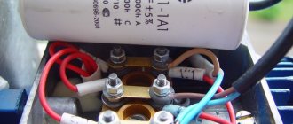
The best option is to use the same type for both capacitors. Typically, the operation of a three-phase motor is ensured by paper starting capacitors, enclosed in a sealed steel casing such as MPGO, MBGP, KBP or MBGO.
Most of these devices are made in the form of a rectangle. If you look at the case, their characteristics are given there:
- Capacitance (uF);
- Operating voltage (V).
How to choose a capacitor
To better understand the algorithm for the correct actions, you can study the process of selecting a capacitor when connecting an electric motor to different power sources. If a three-phase network is used, the capacitance formula is suitable:
Where:
- k – fixed coefficient equal to 2,800/4,800 for the “star”/“triangle” circuit, respectively;
- Iph – current in the stator circuit, which manufacturers indicate on the nameplate or in the accompanying documentation;
- U – supply voltage.
In a simplified version, specialists take 6-7 µF for every 0.1 kW of power consumption. Under significant mechanical loads, the winding may burn out. A soft start of the electric motor is ensured by an additional capacitor. It performs its functions within 2-5 seconds. The capacity is chosen 2.5-3.5 more than the result of the previous calculation. The rated voltage is 50-70% higher than the operating parameters of the power supply network.
An asynchronous motor is connected to a single-phase source. In this option, it is necessary to create a phase shift to start rotating the rotor. Starting is provided by a separate winding. A special capacitor is installed in this circuit. For a simplified selection circuit, take 8-12 μF for every 0.1 kW of power consumption.
For your information. To prevent overheating and damage to parts, it is recommended to connect inductive loads of this type through capacitors designed for an operating voltage of at least 450 V.
Calculation of a quenching capacitor for connecting an LED strip can be done using the formula:
Where:
- I – current in the circuit;
- Up (Ud) – power supply voltage (drop across diodes), respectively.
On what principle does the engine work?
With the help of the influence of alternating electric current, a magnetic field appears in the stator. It can be considered as two separate fields, the amplitude and frequency of which are the same, but the directions are different.
Two magnetic fields that arise in the engine stator act on the rotor so that it begins to rotate and causes the engine to operate. Rotation begins due to the fact that the stator fields have different directions. If there is no trigger mechanism, that is, there is no auxiliary winding, the rotor will never start moving.
If the rotor has started working, rotating in one direction, it can change direction only in the event of outside intervention.
Is it possible to install a larger capacitor?
The exact answer to the question raised in this section can be given after studying a specific diagram. If you need to select a part for a filter (oscillatory circuit), similar parameters are required. Otherwise, the frequency characteristics will not correspond to the design intent.
When smoothing out ripples in the power supply, such an upgrade instead of a standard product can be effective. In some cases, to limit the current in the circuit, you will have to select a suitable resistor. Through it it will be possible to discharge the capacitor without damage. The final decision is made taking into account the factors discussed above. Operating conditions, thermal and mechanical loads are essential. A reasonable increase in costs at the stage of purchasing reliable components will extend the service life of a functional device.