| Site Map |
Also known as vector analysis . And for some, vector analysis, known as field theory =) Finally, we got to this interesting topic! This section of higher mathematics cannot be called simple, however, in future articles I will try to achieve two goals:
a) so that everyone understands what the conversation is all about;
b) and so that “dummies” learn to solve, at a minimum, simple things - at least at the level of tasks that are offered to part-time students.
All material will be presented in a popular style, and if you need more rigorous and complete information, you can take, for example, the 3rd volume of Fichtenholtz or look at the Wiki.
And let’s immediately decipher the title. With the theory, I think everything is clear - in the best traditions of the site, we will analyze its basics and focus on practice. Well, what do you associate the word “field” with?
Grass field, football field... More? Field of activity, field of experiments. Greetings humanists! ...From a school course? Electric field, magnetic, electromagnetic..., okay. The gravitational field of the Earth in which we find ourselves. Great! So, who said that about the field of real and complex numbers ? ...some monsters have gathered here! =) Fortunately, algebra has already been completed.
In the upcoming lessons we will become familiar with the specific concept of a field, specific examples from life, and also learn how to solve thematic problems of vector analysis. Field theory is best studied, as you correctly guess, in a field - in nature, where there is a forest, a river, a lake, a village house, and I invite everyone to immerse themselves, if not in the warm summer reality, then in pleasant memories:
Fields in the sense considered today are scalar and vector, and we will start with their “building blocks”.
First, a scalar. Quite often this term is mistakenly identified with a number. No, everything is a little different: a scalar is a quantity, each value of which can be expressed by only one number . There are many examples of mass in physics: length, width, area, volume, density, temperature, etc. All these are scalar quantities. And, by the way, mass is also an example.
Secondly, the vector. I touched on the algebraic definition of a vector in a lesson about linear transformations it is simply impossible not to know one of its particular forms =) A typical vector is expressed by two or more numbers (its coordinates). And even for a one-dimensional vector, just one number is not enough - for the reason that the vector also has a direction. And the point of application if the vector is not free . Vectors characterize physical force fields, speed and many other quantities.
Well, now you can start harvesting aluminum cucumbers:
Scalar field
If each point of a certain region of space is associated with a certain number (usually real ), then they say that a scalar field is specified in this region.
Consider, for example, a perpendicular ray emanating from the ground. Stick a shovel in for clarity =) What scalar fields can be set on this ray? The first thing that comes to mind is the height field - when each point of the ray is assigned its height above ground level. Or, for example, the atmospheric pressure field - here each point of the beam corresponds to a numerical value of the atmospheric pressure at a given point.
Now let’s approach the lake and mentally draw a plane over its surface. If each point of the “water” fragment of the plane is associated with the depth of the lake, then, please, the scalar field is given. At the same points, you can consider other scalar quantities, for example, the temperature of the water surface.
The most important property of a scalar field is its invariance with respect to the coordinate system. If we translate it into human language, then no matter from which side we look at the shovel / lake, the scalar field (height, depth, temperature, etc.) will not change. Moreover, the scalar field, say, depth, can be set on another surface, for example, on a suitable hemisphere , or directly on the water surface itself. Why not? Is it not possible to assign a number to each point of the hemisphere located above the lake? I suggested flatness solely for the sake of convenience.
Let's add one more coordinate. Take a stone in your hand. Each point of this stone can be assigned its physical density. And again - no matter what coordinate system we consider it in, no matter how we twist it in our hand - the scalar density field will remain unchanged. However, some people may dispute this fact =) Such is the philosopher's stone.
From a purely mathematical point of view (outside the physical or other private meaning), scalar fields are traditionally defined by our “ordinary” functions of one , two , three or more variables. At the same time, in field theory, the traditional attributes of these functions, such as domain of definition , lines and level surfaces, are .
Thus, level lines are closed non-intersecting lines on a plane. Each of these lines corresponds to a certain depth value, and from the corresponding “flat” map we can judge the bottom topography - where there is shallow water, where there are “cliffs”, etc.
Level surfaces are non-intersecting spatial surfaces “nested” within each other. Or “lying” on top of each other. Or... whoever has enough imagination =) Each such surface corresponds to a constant value of the scalar field, for example, a specific temperature.
However, our “ordinary” numbers and functions do not always define scalar fields! I’ll give a classic example with a vector - for definiteness, let’s consider the geometric vector of a plane in some affine coordinate system . What happens if you move to a new basis ? In general, this vector will change coordinates: .
Are vector coordinates numbers? Numbers. But they are not scalar quantities! Because scalars are independent of the coordinate system. Moreover, the coordinates of vectors can be specified by “ordinary” functions - and these functions will not generate a scalar field!
I must say, the transition to the next paragraph was clever:
Vector field
If each point of a certain region of space is associated with a vector with a beginning at a given point, then they say that a vector field is defined in this region.
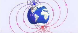
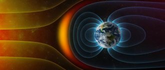
From which it follows that the elements of the vector field are not free , that is, “tied” to points. And why vectors are in “captivity” becomes clear from simple examples. In particular, in the lesson about curvilinear integrals along a closed loop, we conducted a “flat” experiment with a magnet on the table: the closer the piece of iron is brought to the magnet, the stronger it is attracted. And this force at one point or another on the table surface is precisely characterized by the magnetic field intensity vector. The stronger the attraction, the longer the vector, and its tip, of course, indicates the direction of the force.
But much more often, vector fields are considered in three-dimensional space, please: our Earth is the same larger magnet. Another example is its gravitational field. The further from the surface, the lower the force of gravity and the shorter the corresponding force vectors. By the way, where are they “looking”? Simply put, they are all directed towards the center of our planet.
A large group of vector fields is formed by the so-called velocity fields. Look at the field (which has grass) and mentally outline an arbitrary spatial area above it. Imagine that the wind is blowing over the field - a small hurricane for greater clarity. Now let’s fix a certain moment in time and assign to each point of the constructed area a non-free vector that characterizes:
a) the direction of air movement at a given point; b) and the speed of its movement at a given point - the higher the speed, the longer the vector. If there is calm at some point, then a zero vector is associated with it.
The set of these vectors forms the vector field of wind speed at a given time.
The field of fluid flow velocities is structured similarly - for example, each point of a river at some point in time can be associated with a vector indicating the direction and speed of fluid flow at that point.
Why are there wind and rivers, the velocity field can be simulated with your own hands, all you need to do is wave your hand. Or even blink an eye.
...What a nightmare! – vectors are all around us! In horror films, this role is played by zombies or the living dead, but in reality, here it is, it turns out to be VECTORS.
From a formal mathematical point of view, vector fields are defined by vector functions that have already been discussed in other topics:
For the “flat” case, this is a vector function that assigns non-free vectors * Work of a vector field . If the functions of two variables are defined for any “x”, “y”, then the vector field will be defined on the entire plane.
* Further, by default, we assume that all things take place in the Cartesian coordinate system
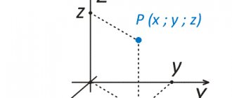
With three-dimensional space, everything is similar: – here, each permissible point in space is associated with a vector with a beginning at a given point. “Admissibility” is determined by the domains of definition of functions, and if each of them is defined for all “X”, “E”, “Z”, then the vector field will be specified in the entire space.
! Notation : vector fields are also denoted by the letter or, and their components by or, respectively.
From the above it has long been clear that, at least mathematically, scalar and vector fields can be defined throughout space. However, I was still careful with the corresponding physical examples, since such concepts as temperature, gravity (or others) may not exist at all somewhere. But this is no longer horror, but science fiction =) And not only science fiction. Because the wind, as a rule, does not blow inside the stones.
It should be noted that vector fields (the same velocity fields) can change over time, and therefore in many physical models an additional independent variable is considered. By the way, the same applies to scalar fields - temperature, in fact, is also not “frozen” in time.
However, within the framework of mathematics, we will limit ourselves to the trinity, and when such fields “meet” we will imply some fixed moment in time or a time during which the field has not changed.
Vector lines
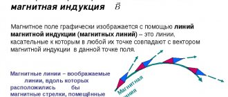
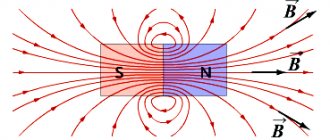
If scalar fields are described by lines and level surfaces , then the “shape” of a vector field can be characterized by vector lines. Probably, many remember this school experience: a magnet is placed under a sheet of paper, and iron filings are poured , which are precisely “aligned” along the field lines.
I’ll try to formulate it more simply: each point on a vector line is the beginning of a field vector that lies on the tangent at a given point:
Of course, line vectors in the general case have different lengths, so in the above figure, when moving from left to right, their length increases - here we can assume that we are approaching, for example, a magnet. In physical force fields, vector lines are called force lines. Another, simpler example is the Earth’s gravitational field: its field lines are rays with a beginning in the center of the planet, and the gravity vectors are located directly on the rays themselves.
Vector lines of velocity fields are called current lines. Many streamlines give us an idea of the flow of a liquid or gas at a given time. By the way, a streamline and a particle’s trajectory are not the same thing. If the velocity field does not change over time (for example, a river with a steady flow), then, yes, the trash cans will float along the current lines. Such a field is called stationary, and in it the trajectories of particle motion coincide with the current lines. But imagine a dust storm - here the current lines are different at each moment, and therefore the trash can will fly along its own unique trajectory, and not at all along any specific current line.
In general, many concepts of field theory come from hydrodynamics, which we will encounter more than once.
If a “flat” vector field is given by a nonzero function, then its field lines can be found from the differential equation . The solution to this equation defines a family of vector lines on the plane. Sometimes tasks require drawing several such lines, which usually does not cause difficulties - we chose several convenient values of “tse”, drew some hyperbolas , and order.
The situation with a spatial vector field is more interesting. Its field lines are determined by the relations. Here you need to solve a system of two differential equations and obtain two families of spatial surfaces . The intersection lines of these families will be spatial vector lines. If all components (“pe”, “ku”, “er”) are non-zero, then there are several technical solutions. I will not consider all these methods (since the article will grow to indecent sizes), but will focus on the common special case when one of the components of the vector field is equal to zero. Let's list all the options at once:
if , then the system needs to be solved; if , then the system; and if , then .
And for some reason we haven’t had practice for a long time:
Example 1
Find the field lines of the vector field
Solution : in this problem, therefore we solve the system :
The first diffur is generally a freebie: - a family of planes parallel to the coordinate plane (pictured in mind!).
The second diffur is almost the same :), but why do we need sudden difficulties? – a family (attention!) of parabolic cylinders parallel to the axis.
Answer : the required set of vector lines:
In other words, here in each plane “sits” a family of parabolas.
A similar problem for you to solve on your own:
Example 2
Find the field lines of the vector field
Describe the resulting set of lines. By the way, the condition does not explicitly say which field we are talking about - flat or spatial. In such situations, I recommend solving the problem for space - you can’t go wrong 
A short solution and answer at the end of the lesson.
Vector gradient field
What is your relationship with directional derivative and gradient ? ...no big deal, from hatred to love - one step =) Let me remind you that the gradient of a function at a point is a non-free vector that indicates the direction of maximum growth of the function at a given point and determines the rate of this growth.
Finding the vector function of gradients is a popular and widespread way to obtain a vector field from a scalar field. Provided that the corresponding partial derivatives of a function of two and three variables :
The meaning is very simple. So, if a function specifies the scalar field of the depth of the lake, then the corresponding vector function defines a set of non-free vectors, each of which indicates the direction of the fastest rise of the bottom at a particular point and the speed of this rise.
If a function specifies a scalar temperature field of a certain region of space, then the corresponding vector field characterizes the direction and speed of the fastest heating of space at each point of this region.
Let's look at a general mathematical problem:
Example 3
Given a scalar field and a point. Required:
1) compose the gradient function of the scalar field;
2) find gradient at a point and calculate its length;
3) calculate the derivative in the direction of the normal vector to the surface at the point forming an obtuse angle with the positive semi-axis.
directly relate to solving the problem, but let us immediately note that the scalar field is not defined on all three coordinate planes.
1) Let’s quickly remember how to find partial derivatives of a function of three variables :
Let's create a function that defines the vector field of gradients:
And once again - what is its meaning? The resulting vector function assigns each point in the domain of definition of the scalar field a vector indicating the direction and maximum growth rate of the function at a given point.
And we have to find one of these vectors in the next paragraph:
2) Let's calculate the partial derivatives at the point:
Thus: – I emphasize once again that this vector comes from the point and cannot be moved anywhere! For the reason that it characterizes the direction of the fastest increase in the function precisely at the “em zero” point , and not somewhere else!
The measure of this maximum speed is precisely the length of the gradient:
3) Let us calculate the derivative in the direction of the normal vector to the surface at the point, forming an obtuse angle with the positive semi-axis.
It’s a little tricky, but it’s not hard to figure it out. First, let’s make sure that the point “um zero” really belongs to this surface: The correct equality is obtained. OK.
What kind of surface this is is not of interest to us, what is important to us is its normal vector at the point , and not just any kind, but the one forming an obtuse angle with the semi-axis.
Let’s recall the material from another lesson: the normal vector to the surface at a point is specified as follows:
In this case:
But is this the right vector? How to find out the angle it makes with the semi-axis? ...Today we have some kind of excursion into films... =) and now the film “Total Recall” is up next. Let us calculate the scalar product of the vector with the direction vector of the positive “Z” semi-axis:
, therefore, the angle between these vectors is acute, which does not suit us!
And therefore you need to choose the oppositely directed normal vector:
Let us note at the same time that normal vectors, unlike gradients, are free; their task is only to indicate the direction.
Let's calculate the direction cosines of a given direction, or, which is the same thing, the coordinates of a unit vector codirectional with the vector:
Control:
Thus, the desired derivative in direction:
Let me remind you that this value characterizes the growth rate of the function at a point in the direction of the vector, and it cannot be greater than (the maximum growth rate at a given point).
Answer:
A small example for your own solution:
Example 4
Find the angle between the gradients of scalar fields and at a point
Simple and tasteful. ...How to find an angle? – using the same scalar product . Well, obviously, here you will have to “shake up” multi-level fractions and some trigonometry . A short solution and answer at the end of the lesson.
What to do if you are offered a "flat" scalar field? Just subtract one coordinate; relevant examples can be found in the article Directional derivative and gradient of a function . Essentially, we re-solved the examples from that article, only with a slightly different interpretation.
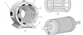
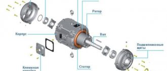
Stator in the motor
The stator cylinder is integrated into the electric motor housing. He is its immovable part. Together, the stator and housing form a single monoblock.
The stator core is made of metal plates. They are isolated from one another by a layer of varnish. The purpose of such a core device is to counteract heating by Foucault eddy currents.
Once assembled, the stator package is pressed into the housing. The stator core is formed by the turns of the winding.
They are impregnated with substances of a special composition that protect the coils from damage, and are placed in specially machined grooves in the inner wall of the cylinder.
The connection diagram of the stator to the electrical network is as follows:
There is a so-called BRNO on the motor body; the disconnection block starts the windings. In other words, this is a distribution box with terminal blocks inside.
Structurally, they differ from each other. The design of the terminal blocks depends on the power of the engine and the type of work that this engine performs. The end parts of all windings are connected to the BRNO terminals.
The method of connecting the windings also depends on the power of the electric motor and its functional purpose.
There are two connection methods. One is the so-called “Star”, the other is the “Triangle”. How the electric motor will operate depends on the connection method.
With the “Star” connection method, the engine smoothly increases speed, and rapid acceleration of speed to the maximum is impossible.
And if the windings are connected by a triangle, the motor can immediately develop the speed for which it is structurally designed, but the starting currents will also be adequately large.
Potential vector field
In the lesson Curvilinear integral over a closed loop, I already spoke in detail about the “flat” potential field, and therefore, before further reading, it will be extremely useful to look at the end of this article. In fact, there will be a continuation now, where we will analyze a similar situation in space.
“Potential”..., what comes to mind here is potential energy, potential possibilities. Thus, a brick lying on a windowsill can potentially be thrown down, and a dent on the ground will non-illusively demonstrate to us that same potential energy. That's right, the Earth's gravitational field is one of the striking examples of a potential vector field.
Let's remember its characteristic feature, having dropped from the windowsill of our cozy village house... no, not a brick, but a feather. From point to point, it can fly along countless trajectories (due to wind, air resistance, etc.), but in all cases the Earth's gravitational field will do the same work to move the feather between these points. Well, different trajectories are already the “contribution” of other forces, which, by the way, can also be described by vector fields.
Note : perhaps here you have a question: “but the wind can lift the feather, and then the work must increase!” Nothing like this. The physical concept of work does not imply that someone or something is “working.” If the wind lifts the feather upward, then it simply reduces the absolute value of the work done by gravity.
In physics there is a specific mathematical model that describes gravitational forces, but in accordance with the focus of the site, I will give only general formulas. So:
A vector field is potential if it represents a field of gradients of some scalar field. A function is called a potential function or simply a potential.
The work of a potential vector field to move a material point from point to point does not depend on the trajectory of its movement and is expressed by the following curvilinear integral of the 2nd kind :
, which is equal to the potential difference.
In other words, in the potential field, only the starting and ending points of the route matter. And if these points coincide, then the total work of forces along a closed contour will be equal to zero:
Let's pick up a feather from the ground and deliver it to the starting point. In this case, the trajectory of our movement is again arbitrary; you can even drop the pen, pick it up again, etc.
Why is the final result zero?
Did the feather fall from point “a” to point “b”? It fell. The force of gravity did the work.
Did the pen hit point "a" back? Got it. And this means that exactly the same work was done against the forces of gravity , and it didn’t matter with what “adventures” and what forces - even if the wind blew it back.
Note : In physics, the minus sign symbolizes the opposite direction.
Thus, the total work done by the forces is zero:
As I have already noted, the physical and lay concept of work are different. And this difference will help you understand well not a feather or even a brick, but, for example, a piano 
Together, lift the piano and lower it down the stairs. Drag it down the street. As much as you want and wherever you want. And if no one called the fool, bring the instrument back. Have you worked? Certainly. Until the seventh sweat. But from the point of view of physics, no work has been done.
The phrase “potential difference” is tempting to talk more about the potential electrostatic field, but shocking your readers is somehow not at all humane =) Moreover, there are countless examples, because any gradient field is potential , of which there are a dime a dozen.
But it’s easy to say “a dime a dozen”: we’ve been given a vector field – how can we determine whether it’s potential or not?
Synchronous motors with permanent magnets on the rotor: control (sine and/or trapezoidal)
Continuing the topic of model-based design, I am publishing another article by Yuri Nikolaevich Kalachev, author of the book Modeling in Electric Drives. Instructions for understanding. This text is still being prepared for publication in specialized publications, but readers of the hub will see it first.
In foreign literature you can find two terms associated with these engines:
- PMSM ( Permanent Magnet Synchronous Motor ) ’s means : permanent magnet synchronous motor ( PMSM ), and this is understandable .
- BLDC ( Brush L ess Direct Current is ’s language as a Brushless Direct Current Motor ( BLDC ) this is not clear. What does direct current have to do with it?
There is considerable confusion with these names both here and abroad.
For example, the term PMSM can be used to refer to a motor with permanent magnets on the rotor, regardless of the shape of its EMF, but it is also often used to mean exclusively the sinusoidal shape of the motor's EMF.
The term BLDC (BLDC) can be used to designate a motor with permanent magnets on the rotor and trapezoidal EMF, or it may generally mean not a motor, but a certain mechatronic unit, including:
- permanent magnet motor with trapezoidal emf
- rotor position sensor
- a semiconductor switch controlled by signals from this sensor.
Actually, this mechatronic unit, which, like a DC motor, can be controlled by constant voltage, gave rise to the term BLDC itself.
Also in relation to synchronous motors with permanent magnets on the rotor in the domestic literature, you can find the name “switch motor” .
The author’s attempts to understand this term quickly reached a dead end, as obvious contradictions were discovered in various sources.
For example, in the book by G.B. Onishchenko “Electric Motors” on page 47 “valve” is a motor corresponding to the term BLDC (BLDC), which assumes a trapezoidal EMF, and this is understandable.
But the manufacturer itself (CHEAZ) calls motors of the 5DVM type “valve-type”, although it claims that they have a sinusoidal EMF.
But Wikipedia: “A valve motor should be distinguished from a brushless DC motor (BLDC), which has a trapezoidal distribution of the magnetic field in the gap...”.
Well... we've arrived...
It is not clear what term and what form of EMF corresponds.
Meanwhile, it is this form that determines the choice of structure of the engine control system.
As a person involved in managing these engines, I would like to suggest:
- To avoid confusion, forget the term “valve motor”
- the term BLDC does not denote a motor, but exclusively the mechatronic unit described above (analogous to a DC motor)
- divide synchronous motors with permanent magnets on the rotor (PMSM) according to the type of EMF into two groups:
1) with sinusoidal EMF (hereinafter, for brevity, PMSMs)
2) with trapezoidal EMF (hereinafter, for brevity, SDPMt)
Control
When controlling motors with sinusoidal EMF, vector control is used (described in detail in the book at the link). From the point of view of capabilities and quality of management, this is the best option.
However, motors with trapezoidal EMF, due to the simpler design of the stator windings and the possibility of simpler control, are used quite often.
Engine design
The shape of the EMF is determined by the design of the motor.
The rotor of synchronous motors is a magnet with a different number of pole pairs.
Figure 1 shows possible stator winding designs. Typically, sinusoidal EMF corresponds to “distributed” winding, and trapezoidal EMF corresponds to “lumped” winding.
Figure 1. Stator winding designs
The stator winding of a motor with a trapezoidal EMF is simpler and more technologically advanced, due to this the price of such a motor is slightly lower.
Next, we will dwell in more detail on a motor with a trapezoidal EMF (SMPMt)
A motor with one pair of poles will look in cross-section as shown in Fig. 2.
Figure 2. Sectional diagram of a motor with one pair of poles
Three windings (A, B, C) are wound on the SDPM stator, shifted in space by 120°. Each winding consists of two sections connected back to back. Thus, when current flows in the winding, it creates two poles inside the motor (positive and negative), to which the magnetic rotor is attracted. Alternately changing the currents in the windings switches the poles of the windings and makes the rotor move after the field. The operating principle of the engine is based on this.
In what follows, we will consider zero the angular position of the rotor at which the rotor flux vector coincides in direction with the axis of phase A (axis of winding A).
Equilibrium equations for stator windings of PMSM in the ABC system
The equilibrium equations for the stator windings of a motor when it is connected to a “star” in stationary phase coordinates ABC have the form (1).
Here:
- — phase voltages
- — flux linkage of phase windings
- — phase currents
- - active resistance of the phase winding.
The flux in the winding of each phase is formed from the following components:
- flux induced by the phase's own current
- flux induced by magnetic fields of other phase windings
- flux induced in the winding by the rotor magnets.
Let us illustrate this with system (2):
- Where:
— inductance of phase windings
— mutual inductances of windings
— flux linkages induced in the windings by the rotor magnet.
In the general case, all inductances of system (2) can be variable functions of the field rotation angle.
In the particular case of a non-salient-pole motor (with a cylindrical rotor), the inductances and mutual inductances of the windings do not depend on the angle.
Designating - the inductance of the phase winding,
is the mutual inductance of the two phase windings, and substituting expressions (2) into system (1), we obtain expression (3):
Noticing that the time derivatives of the flux linkages of the rotor magnets
- is nothing more than induced by magnets
rotor in these EMF windings, system (3) can be rewritten in the form (4).
Now let's introduce the concept of a unit function of the EMF shape.
The unit function of the EMF shape is a function of the field angle (), which has a unit amplitude and follows the shape of the EMF. For phases A, B, C, we denote these functions: .
Using unit shape functions, instantaneous EMF in phases can be represented by expression (5):
- Where:
— amplitude of flux linkage of the rotor and phase winding
— field rotation speed
— rotor rotation speed
— number of pairs of motor poles.
The dependences of the unit functions of the EMF shape of the PMSM windings on the field rotation angle are presented in Fig. 3.
Rice. 3. Unit functions of EMF forms
Derivation of the formula for calculating the electromagnetic torque of PMSMt
The torque produced by a motor is the sum of the torques produced by its windings.
Let's look at the equilibrium equation of winding A from system (4).
Multiplying both of its parts by the winding current, we obtain an equation for the instantaneous electrical power of the winding:
Let's consider the components of this power:
- - reactive power of the winding
- - active power dissipated in the winding
- — power that creates an electromagnetic torque.
If we neglect losses during the transition of electrical power to mechanical power, then we can write:
- Where:
— electromagnetic torque of the engine
— angular speed of rotation of the rotor.
Substituting the EMF values from relations (5) into formula (6), we obtain a formula for calculating the electromagnetic torque of the rotor (7).
Switching windings of SDPMt
In accordance with formula (7), the torque of the PMSM is proportional to the sum of the products of phase currents and the function of the shape of the corresponding EMF.
The maximum value of the winding EMF corresponds to the flat sections of the EMF trapezoid. If we were able to generate currents of some constant amplitude in these sections of the angular trajectory in the windings, for example, coinciding in sign with the sign of the EMF, then this would make it possible to form a maximum constant positive moment at these currents.
For example, consider in Fig. 3 the section of the angular trajectory from π/6 to π/2. In this section, the EMF in phase A has the maximum negative value, and in phase B the maximum positive value. Consequently, to obtain a positive torque in this section of the angular trajectory, it is necessary to provide a negative current value in phase A and a positive current value in phase B. To do this, phase A can be connected to the negative pole and phase B to the positive pole of an external constant voltage source (Udc). In this case, phase C is not used (disconnected from the Udc source).
The amount of current flowing through the windings will, in turn, be determined by the voltage applied to the windings, the magnitude of the EMF and the parameters of the windings.
If we reason in this way, we can compile a table of winding switchings that provide, depending on the position of the rotor, a torque of the desired sign (Table 1).
Table 1. Commutation Law
The windings of a three-phase motor can be switched to an external voltage source using a three-phase bridge inverter. To do this, the state of the inverter must be made dependent on the position of the rotor. This is usually done using a rotor position sensor (RPS). This sensor has three channels. Each channel produces a pulse corresponding to half the rotation period per engine revolution, while the pulses in the channels are shifted by 120°.
Logical processing of DPR signals allows you to determine which of the six sectors the rotor is currently located in.
The operation of the DPR is explained in Table. 2.
Table 2. Work of the DPR (definition of the sector)
Possible structure of the PMSM torque control system
The algorithm described in Table 1 assumes the flow of the same current in two phases of the motor at a unit value of the EMF shape function in the phase windings. Therefore, expression (7) can be rewritten as (8).
Where: - current value in phases.
That is, the torque value is proportional to the current in the motor windings.
The structure of the torque control system in a drive with PMSM following from formula (8) is shown in Fig. 4.
Figure 4. BLDC Torque Control System
This structure allows you to obtain the required torque by generating a current of the required amplitude in the motor windings, while maintaining the switching algorithm (Table 1).
This problem is solved by creating a current circuit with PWM based on a three-phase bridge inverter.
The current regulator (PI-reg.) generates a signal to set the winding voltage (U), which is then implemented by an inverter with PWM in accordance with the switching algorithm (Table 1).
As a feedback signal in the loop, you can use three-phase rectified signals from phase current sensors or a signal from a current sensor in the inverter DC link ().
Based on the considered torque control channel, it is possible to build external speed and position control loops.
However
If the currents in the windings dropped to zero and increased to the desired level instantly, then the motor torque, determined by their magnitude, would be constant in steady state. In reality, real transient processes when switching windings lead to torque ripples. Depending on the parameters of the windings, as well as the ratio of the current EMF values and the DC link voltage, these pulsations can be different in duration, amplitude and sign.
In addition to these switching ripples, the system under consideration will also have torque ripples at the PWM frequency.
Below is an example of how the speed control system model works. This model was built in the SimInTech using elements of the specialized “Electric Drive” toolbox. The environment makes it possible to obtain the maximum approximation of the simulated processes to reality, taking into account the effects of time and level discretization.
Part of the model, namely the model of the digital speed control system, is shown below in Fig. 5. The system speed controller (Reg.W) produces a torque signal, which is processed by a structure built in accordance with Fig. 4.
Figure 5. Digital control system model
An engine with the following parameters was selected for control:
- Rs = 2.875 Ohm — phase winding resistance;
Ls = 8.5e-3 H – phase inductance;
F = 0.175 Wb – rotor flux linkage;
Zp = 4 - number of pole pairs;
Jr = 0.06 kg m2 - moment of inertia of the rotor.
The voltage in the DC link of the drive was assumed to be 100V.
PWM with a frequency of 5 kHz was used in the electric drive current circuit.
During the regulation process, there was a stepwise increase in frequency at a constant moment of resistance on the motor shaft (10 Nm).
The graphs obtained during the operation of the model are shown in Fig. 6.
Figure 6. Simulation of engine operation
The torque graph shows significant ripples.
Note that they are mainly associated precisely with transient processes when switching windings and, accordingly, have a frequency that is sixfold in relation to the given one.
The ripples associated with PWM are small in this case.
Note that switching ripple increases significantly with increasing torque, which is associated with an increase in current.
What helps somewhat is that their effect on speed is reduced by inertia.
Is it possible to vector control a PMSM?
If you really want to, then you can. However, this is not without its peculiarities. The mathematics and structure of a standard vector control system is based on the sinusoidality of the field in the gap. With a trapezoidal EMF, this condition is violated, although not very much (a trapezoid is almost a sine).
And the result of this “almost” will, again, be pulsations of the moment.
The model of a digital vector speed control system in the SimInTech is shown in Fig. 7.
Figure 7. Part of the vector control model.
Below, Fig. 8 shows the operating graph of the model of the previously discussed PMSM operating in the previously discussed mode, but under the control of a vector system.
In the moment graph we again observe ripples (although they have decreased somewhat compared to the previous version).
The reasons for pulsation in vector control and DPR control are different, but the frequency is still the same - sixfold in relation to the given one.
Note that due to the non-sinusoidal nature of the EMF, the currents in the motor windings will also be fundamentally non-sinusoidal (this is true, although on the scale of the figure it is not very noticeable).
Figure 8. Motor operation under vector control
Is it possible to control a motor with a sinusoidal EMF using winding switching using DPR?
From the author's point of view, it is possible - but not necessary.
Along with the commutation pulsations of the torque, the sinusoidality of the EMF (the absence of a flat top of the trapezoid) in this case will inevitably cause additional pulsations, which reduce the quality of regulation even in comparison with a PMSM motor controlled by the DPR.
And with vector control of a motor with a sinusoidal EMF, there will be no torque ripple.
To confirm this thesis, below (Fig. 9) are graphs of the operation of a motor model with the previously discussed parameters, but with a sinusoidal EMF and a vector speed control system.
It can be seen that torque pulsations in this case are practically absent. When the system regulators are correctly configured, they are associated only with PWM conversion and are almost invisible in this case.
Figure 8. Motor operation with sinusoidal EMF
Results
For synchronous synchronizers with trapezoidal EMF - switching according to DPR.
It is also possible to use a more complex vector control algorithm, which can reduce the level of torque ripple.
For synchronizers with sinusoidal EMF, the best option is vector control.
This combination is ideal for building a precision electric drive (which was already understandable).
Kalachev Yu.N.
Models for self-study can be found here.
Previous articles on the topic:
Model-based design. Electric drive with brushless DC motor
Model-based design. Construction of an active rectifier (based on a mathematical model)
Bibliography
[1] A. S. Pushkin “Poltava”.
